
mtnickel
-
Posts
335 -
Joined
-
Last visited
-
Days Won
5
Content Type
Profiles
Forums
Blogs
Events
Gallery
Downloads
Store
Posts posted by mtnickel
-
-
9 minutes ago, Michael said:
Chiming-in with a bit of an obvious question here...
Some of us are pretty keen on replacing the differential, half-shafts, companion flanges and stub axles. But not necessarily the Chapman struts... especially if we've gone through the trouble of replacing spindle pins and sourcing that most elusive of animals, namely straight/true control arms and Chapman struts (many had the uprights welded askance). That being so, is there any possibility of replacing the aforementioned driveline parts, but fitting them into the factory Chapman struts? Or do the struts have to go?
It'd be a ton of machining to be able to somehow bolt the mustang Bearing to the stock strut. Otherwise it'd be next to impossible to somehow get the mustang CV end and hub to work in the stock bearing housing.
You're not replacing your "straight/true" control arms...they will be utilized.
I am utilizing the stock strut tube. I'll be cutting it off, caping the bottom appropriately, and then welding to the new hub housing. It's more or less just fabricating a new chapman strut housing, but all the hard part of that fabrication is done for you.
SIDENOTE for this thread...if anyone has modified the mustang hub for 4 bolt use, please let me know. Just wanting to know the nitty gritties if you somehow reinforced the hub or just utilized relocated studs in the thinner portion of the hub.
-
This might explain a few of them.
This guide is old and verbose and not great, but could help.
https://www.dropbox.com/s/bwjujmf4ixtzmhb/Final RB Guide Draft 4.docx?dl=0
If you're using the stock ECU, I have a nistune setup if you're wanting to tune it.
You are going down the right track as far as stripping the harness to make things fit...especially if you are converting to the Greddy style manifold. I originally just tapped into wires needed and bundled everything else up, but I got fed up with the mess after a while and did as you said. It was quite the rats nest, but I stripped the harness to whats needed and cut out all the excess.
Some of the big spade plugs were deleted completely once sorted
What gen is your RB25?
-
There’s a PDF in my FS thread frogon posted. Covers anything and everything on the swap.
First of all, don’t spend any money modifying those axles. They’re actually not that strong and much much smaller shaft than the OE z31t axles. Though it does matter what power you’re running, along with intended use, trans type, and tire traction.
Secondly, did the silvermine kit come with any documentation on how to weld? Did you adjust it all so that it’s centered? When designing ours we found out the square part of the flange is not concentric. If you have a dial gauge, try to measure your runout.
I’m curious how thick the center part of the silvermine adapters are, as they are adding to the problem of being too tight. That’s why I decided to design these. With the rock auto axles mine just BARELY fit on the passenger side.
Was it only the passenger side you had problems with?If that’s the case, I have a solution for you. You could buy another driver side axle. It is shorter. But you will have to swap the diff side Cv end from the passenger unit as the splined end is longer on that side and a DS axle can’t be swapped in as is. They’re actually pretty cheap I think ($75?).
If you’re over 300whp and intend to drag race, then it might not be the best solution as you’ll probably break them anyways. In that case I’d keep eye out for z31T axles.
Also, the axle is tightest when at full droop. You could install droop limiters to limit how close it gets. You should find if you jack up the suspension 1-1.5” you suddenly have more room.
Anyways, rambling now, message me if you have questions.
-
6 hours ago, Patrick allaire said:
Are these still available Wasn't able to contact
Messaged you back. Yes, i think about 10-15 sets available.
-
To add to this thread,
I picked up an 08 Prius motor.
One really nice thing about the Prius vs Vue motor is that the motor orientation is opposite, and the bracketry is minimal. In the Prius the computer is remotely mounted.
I think locating in the Z will be much much easier as it will angle up and to the right towards the radio. Lots of room above the gas pedal.
Will document the swap here. pd $150cdn for motor and Ecu and all wiring I wanted from the Prius (got lots of the thick white 8 gauge).
-
3 hours ago, Glenn said:
Are you still offering these for sale? If so, I would love a set.
I am. Currently about 12 sets left. I plan on making more if there is a demand.
-
 1
1
-
-
2 hours ago, Ironhead said:
I know...I have so many photos on the net from over the years that I hosted on Photobucket....no way I am going back to rehost them all.
When PB pulled their initial round of BS back in 2017 I switched to Imgur. It is free and easy to use. Eventually PB relented and the photos started to show up again. But now, after this most recent crap with blurring the images and extorting us for money, I went to PB and deleted all my photos, just to be done with them. I honestly think they will fold soon.
I am wiring my Z from scratch, with a PDM, and I am just trying to figure out how to get the park function to work. Most of the DIYs on the subject approach the topic from the angle of integrating the Honda wiper motor with the stock Z wiring. I don't have the stock Z wiring, so I'm a bit lost.
I know green/black is +12V.....black is ground....blue to ground is slow wiper....blue/yellow to ground is fast wiper. I just cannot wrap my head around what to do with the blue/white wire to get the wipers to park.
Broken images fixed with Imgur.
So you're not using the stock switch? What type of wiper switch do you have? I'd start there. From the above diagrams, you might need more than just 3 wires. when in double I can show you how to wire a single interrupt switch that will park it.
The Honda motor will give you ground on that blue/white wire when the wiper is in mid stroke. So you may need some sort of relay. Show us your switch first and we may be able to help. if in a pinch, i'm sure I can show you how to wire it as a push button that you hold to park.
-
5 minutes ago, Ironhead said:
I'm trying to sort this all out on my car ATM. Of course Photobucket has once again screwed up the internet by blurring out the images, so I'm not getting much out of it.
Why doesn't Photobucket just hurry up and go out of business?
Ideas for where to rehost? wish there was some forum macro that could come and redo all them automatically.
-
1 hour ago, Jboogsthethug said:
Interesting, that’s the first I’ve heard of one of these! Is this what you’re talking about?
Found it, 94-00 integra. See my post:
-
21 minutes ago, Jboogsthethug said:
Hey @5thgenluder, I can’t find details on this in the thread: how did you block off the evap tank? Did you just connect the lines to each other? And what did you do with the filler neck hole? Any problems with fuel overall?
I kept all the Evap lines. The one that went to the engine I instead connected to a fuel tank check valve. It’s like a valve that lets air in when fuel contracting but also seals below like 1-2psi to keep vapours from leaking out. I grabbed it from a civic or something.
-
Messaged. I can host a Dropbox link
-
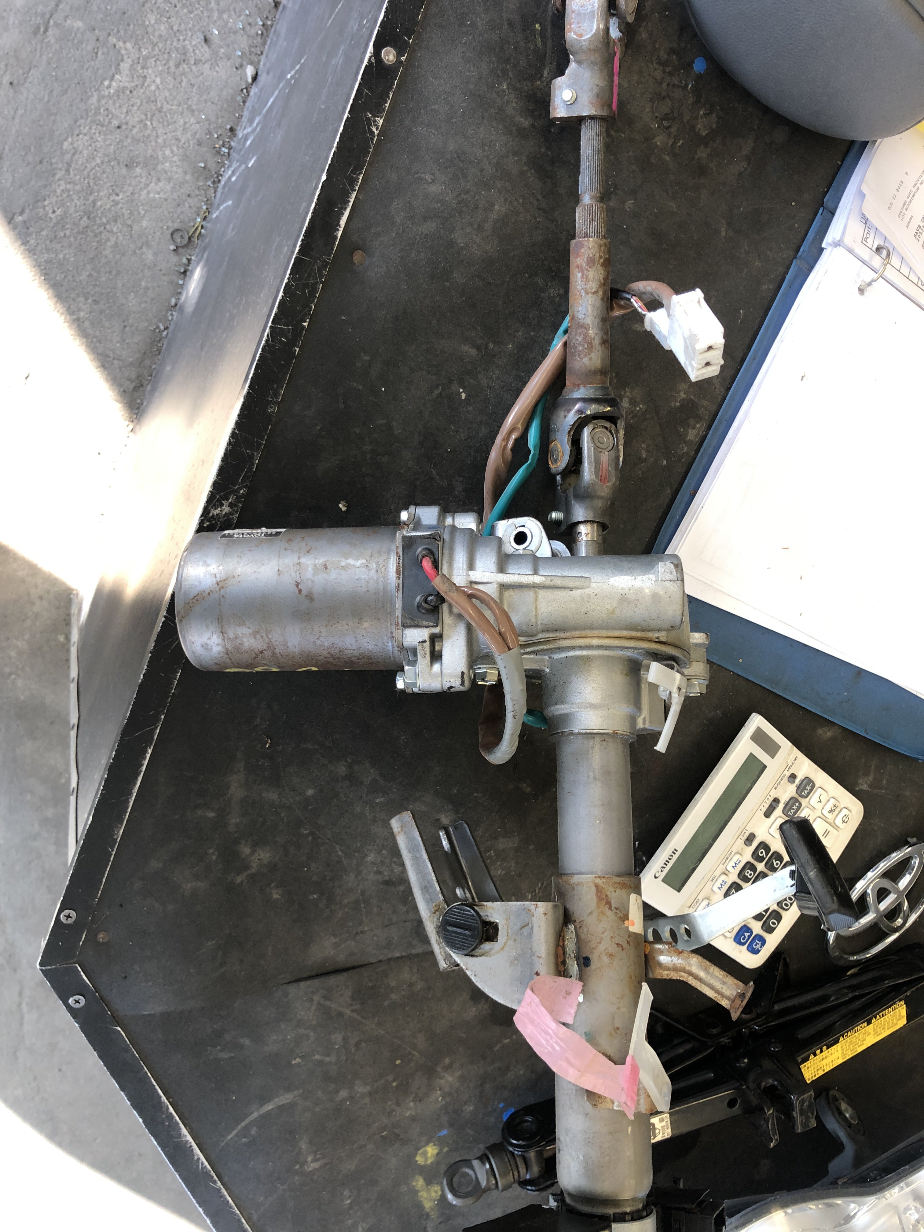
I know many systems reduce assist the faster you go. That could certainly have an impact on highway driving. The system basically should not assist much at higher speeds.
I got the Yaris non-abs computer as this one uses a direct speed input and not can bus. Had hoped to play with tricking the speed ( over read my stock speed to reduce assistance faster, or maybe some variable curve). But all this driveability and feel complaints have got me wondering whether it’s worth the effort. Perhaps the heavy parking lot steering is just the cost of admission for an old car.
-
1 hour ago, studioti said:
@mtnickel
Would like to purchase a set of these adapter plates, plus rental of the jig and PDF instructions to get perfectly centered.
How do I go about paying you ?
One more thing... you mention "flipping the cages" to make the z31t axles shorter....where can I find more info on that so when I rebuilt my axles...I can do that mod.
Thanks
James
Will message you regarding purchase.
All other questions covered in PDF
https://www.dropbox.com/s/23dj8il5rru20i3/Z31%20Turbo%20CV%20axle%20ConversionV4.pdf?dl=0
-
1
-
-
2 hours ago, daffleck said:
I have a 76 with the same setup. R200 with 3.54 ratio. Silvermine motors makes the adapter for 180 bucks. They also have a complete kit with axles. The CV axles I purchased was from rock auto. 84-89 Nissan 300zx turbo, Z31. Work great. Just tig weld the adapter to the companion flange. I paid a hotrod shop to do the perfect welds and I still have about 400 bucks into that part of the project. Good luck to what ever you decide.
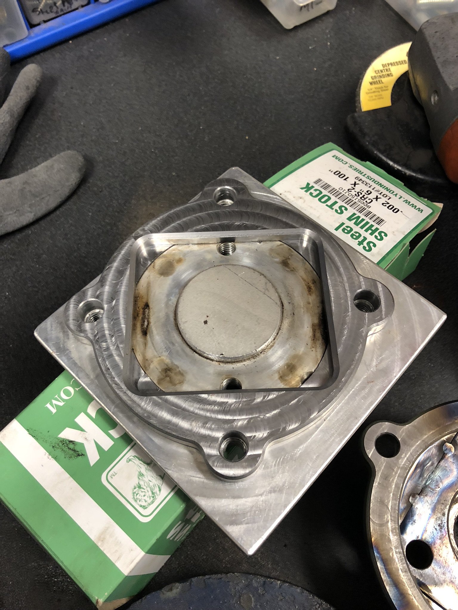
Just make sure the shop that welds yours Centers the square flange in the adapter. The stock square flange isn’t concentric and if they just throw it in the adapter and weld you’ll be SOL. It make have lots of runout and vibrate.
We designed a jig to locate the adapter ring to the stock flange for welding. It also clamps it flat so the part doesn’t warp while welding.
-
Love what you've done here! Axle setups are few and far between, and we need all the options we can get. I'm in a similar situation in that I make the weld-on Z31T flanges for sale mainly on DPAN, but here as well. I too make them just for the hobby of it. However, my part really is not an ideal solution, as finding old OEM axles is becoming more and more difficult. Keep up the good work and we look forward to seeing what you come up with.
If what you have was available when i started, i'd have sourced a $400 STI diff, and $880 set of your plug in axles and be done with it. Plug and play.
My 3.90 R200 was $250, LSD was $500, Axles were $250, making custom flanges was at least $250, having them welded another $100. That's $1350 and still doesn't include new mustache bar, and the labour to setup the diff, etc etc.
Are the Plug-in STI style axles welded on the splined side as well? any possibility of using an OE type STI end there?
-
Lots of good info here.
Some theory is also, depending on how solid your diff mount is, sometimes they have the diff slightly more nose down (1/2-1*) so that under load it straightens up to match angles. You can also play with diff angles by 1) moving where the washers are around your mustache bar (can put poly directly against chassis to raise rear of diff and level it more), or 2) putting washers between your diff mount and the diff (if it's stock mount, the more washers to more nose up it gets). You get the idea.
-
14 minutes ago, jpndave said:
Sorry to hear about the problems. If the splines are loose on the stars, meaning you can twist the star on the splines - scrap metal.
However, the stars sliding may not be a problem. If you look at the picture I posted above you can see that the splines are long and there is no shoulder inside. On the Porsche 930 style joints, in a non-steering application, at least one or both joints float on the shaft to allow for changes in length as the suspension cycles. The cups inside the joints need to allow for the movement. Basically the shaft floats between the two snap rings stopped from going "in" by the outer ring and going "out" by the inner. As long as lengths and clearances are correct and not binding it should work.
On a cv/tripod setup, the tripod takes up the length change and the cv is set ridgid like those shafts you have. Tripods are heavy and weak but necessary in a steering application. Manufacturers sometimes use them as it can be a cheaper/less precise solution in the rear and they will take up substantially more length change. In that style the star needs to be contained as tripod will just slide out. Maybe an inner snap ring would do it if your second joint is a tripod.
Food for thought anyway.
I thought that was only something the VW dune buggy guys did. They lengthened and loosened the splines to allow extreme suspension travel. I don’t think it was something the original 930 used.
I was aghasted by the amount of slop in an unnamed 930 based CV conversion for the Z I bought. The end to end rotational play was 1/2” (at the 6” diameter. Not sure what that corresponds to in degrees). Compared to any other axle I’ve held it was not confidence inspiring and I can imagine the driveline clunks that would result.
I have a set of true 930 CVs downstairs that I can check. Bought them with plans to make a proper cv conversions, but went z31t after more thought.
With the the scope of the project at hand and its goal of a bulletproof setup, sliding sloppy spines aren’t in the cards I’d guess
-
They’re probably as strong as like stock 240sx axles.
Youre best off looking for used z31t axles. They are much beefier and will hold the power.
-
1 minute ago, Cable said:
Excellent. I will hit you up later this week.
How do these would with the Rockauto Turbo CV Z31 that are running the tripod setup vs the OEM cage? I thought I read you can't shorten the tripod style. I have a 280z btw.
The show one shaft at 20 5/8" and the other at 19 27/32".
Not sure what pic you looking at. The oem z31t can only be shortened like an 1/8”, but that little bit is appreciated and useful.
The rockauto can’t be shortened, but already happen to be ever so slightly shorter and do fit with these adapters without binding. They however are probably only strong enough for 300hp or so;maybe more, maybe less, depending drivetrain and tire traction and abuse.
Maybe in the pic I had a passenger side of one and a driver side of the other.
-
21 hours ago, Cable said:
I like this option..... how much for a pair?
$225 shipped plus PayPal fees. But it now includes a jig to aid with welding. You must ship the jig back or to the next user.
-
On 5/29/2018 at 3:40 PM, rabrooks said:
I expect this is the route I will go. I'll use the Z31 axles and your flange adapter. The the diff end pretty much takes care of itself. and the outer end bolts to the adapter flange? Are you saying the 930 axles are the correct length or does the adapter make up some difference. I thought the cv setup might be lighter and more mechanically efficient.That's mostly what I was interested in.
930 is a Porsche style CV. You don’t use 930 axles. You can use 930 CVs (just the joints) with a custom shaft (which is available due to all the vw dune buggy guys using this type of thing), and adapters at both the diff side and Hub side.
CV setup may not be lighter, but probably more efficient, less vibration, and more durable. Also, can replace the CV with off the shelf part If need be.
-
On 1/4/2019 at 8:52 AM, Gollum said:
Yeah, PATS can be disabled. Some engine wreckers even offer that as a service when you buy an engine from them. The ford performance kit I linked wouldn't have that issue.
It’s iust a cost thing. If you have access to the parts car, the oem harness is pretty complete. Also the service manual for ford is very good and easy to read. I figured out which wires needed power or ignition power fairly in a few hours. PATS removal was $250 sent to Eric at HP tuners.
-
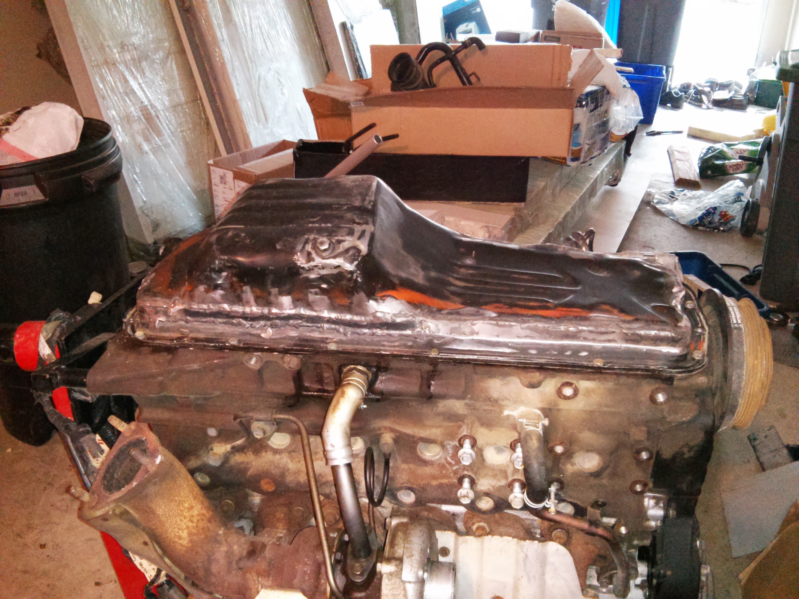
I'd almost rather not say...🤭
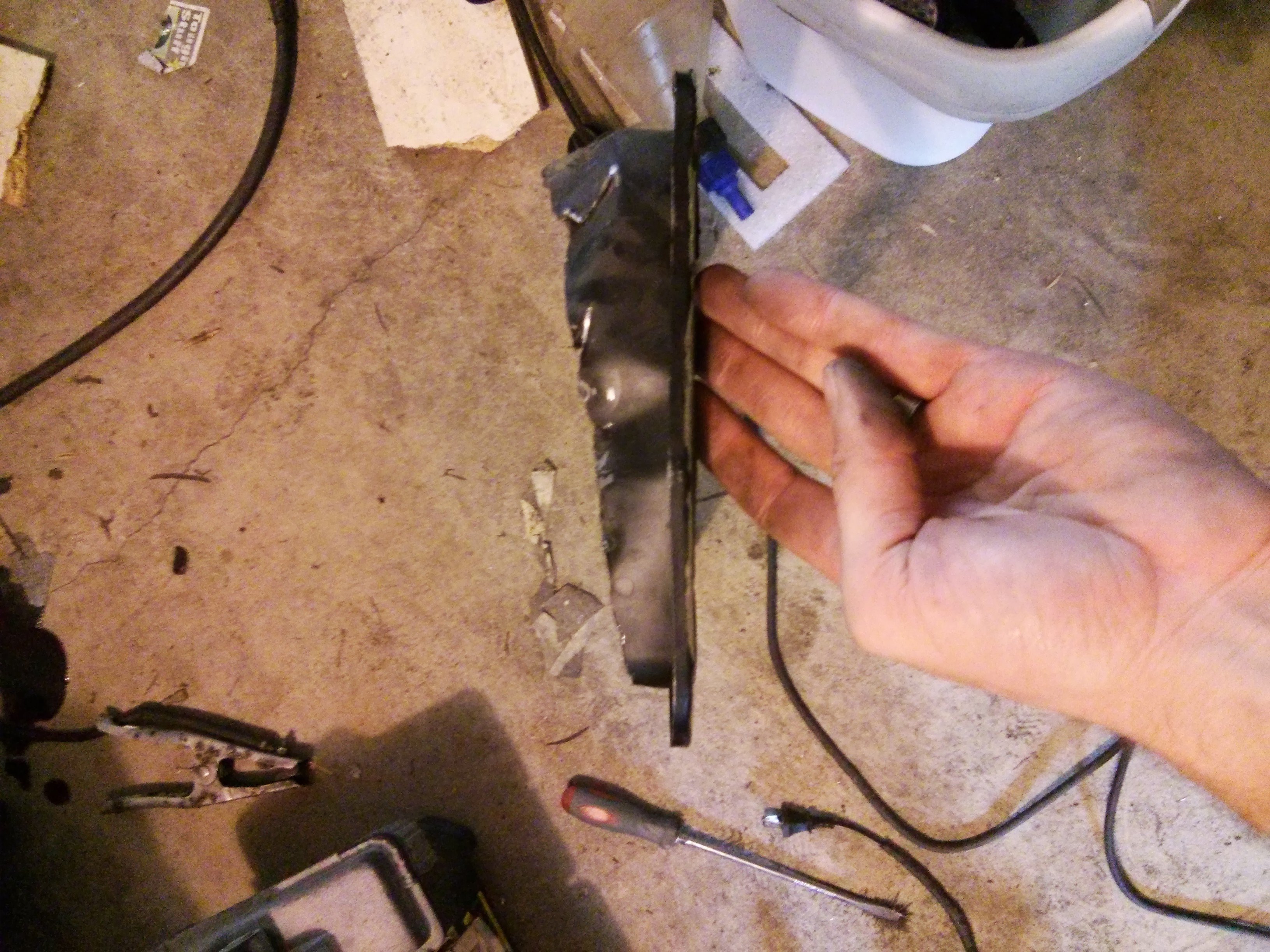
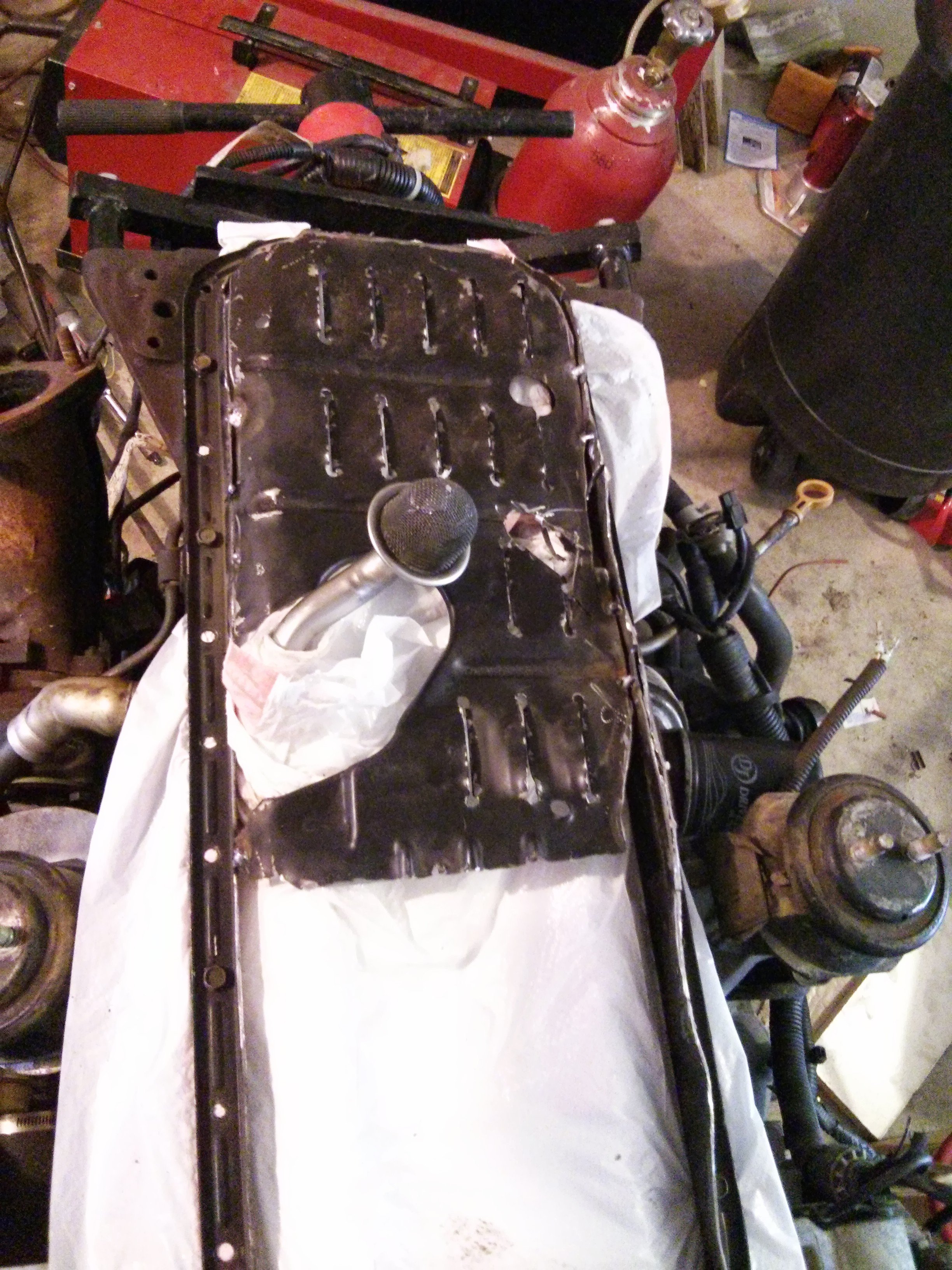
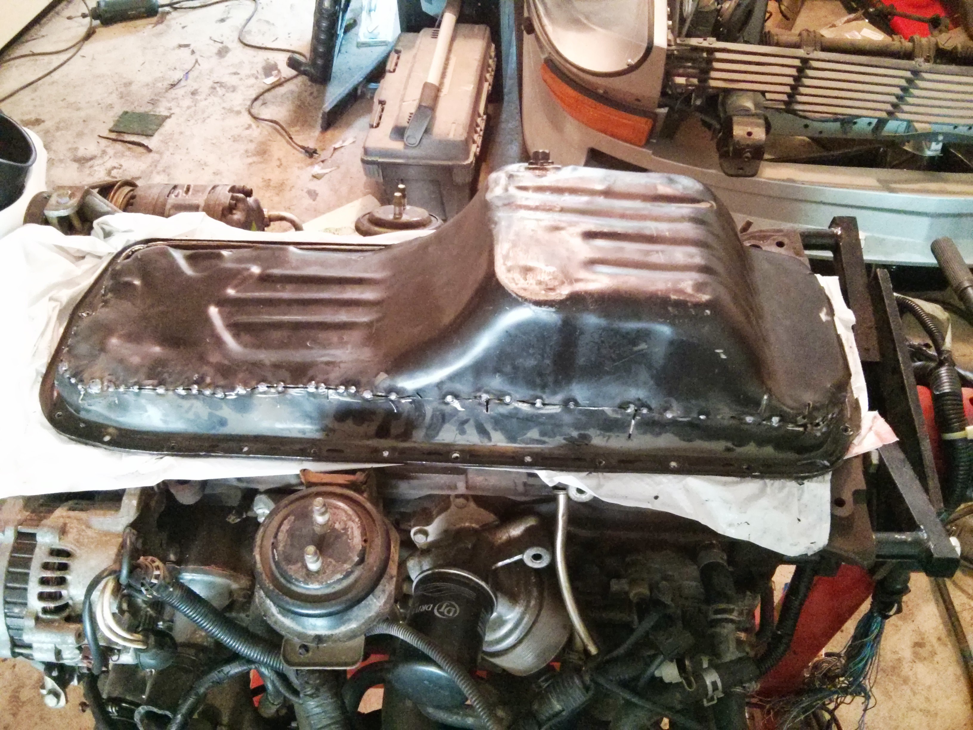
once i welded them all up and ground them down i mixed up a batch of JB weld and applied it over all the welds. lol. redneck, but effective. If you were really OCD, you could silicone your pan down to a flat surface and then pressure test it through the drain plug. Spritz it with soapy water and look for bubbles.
Instead of JB weld, epoxy primer would probably seal as well.
-
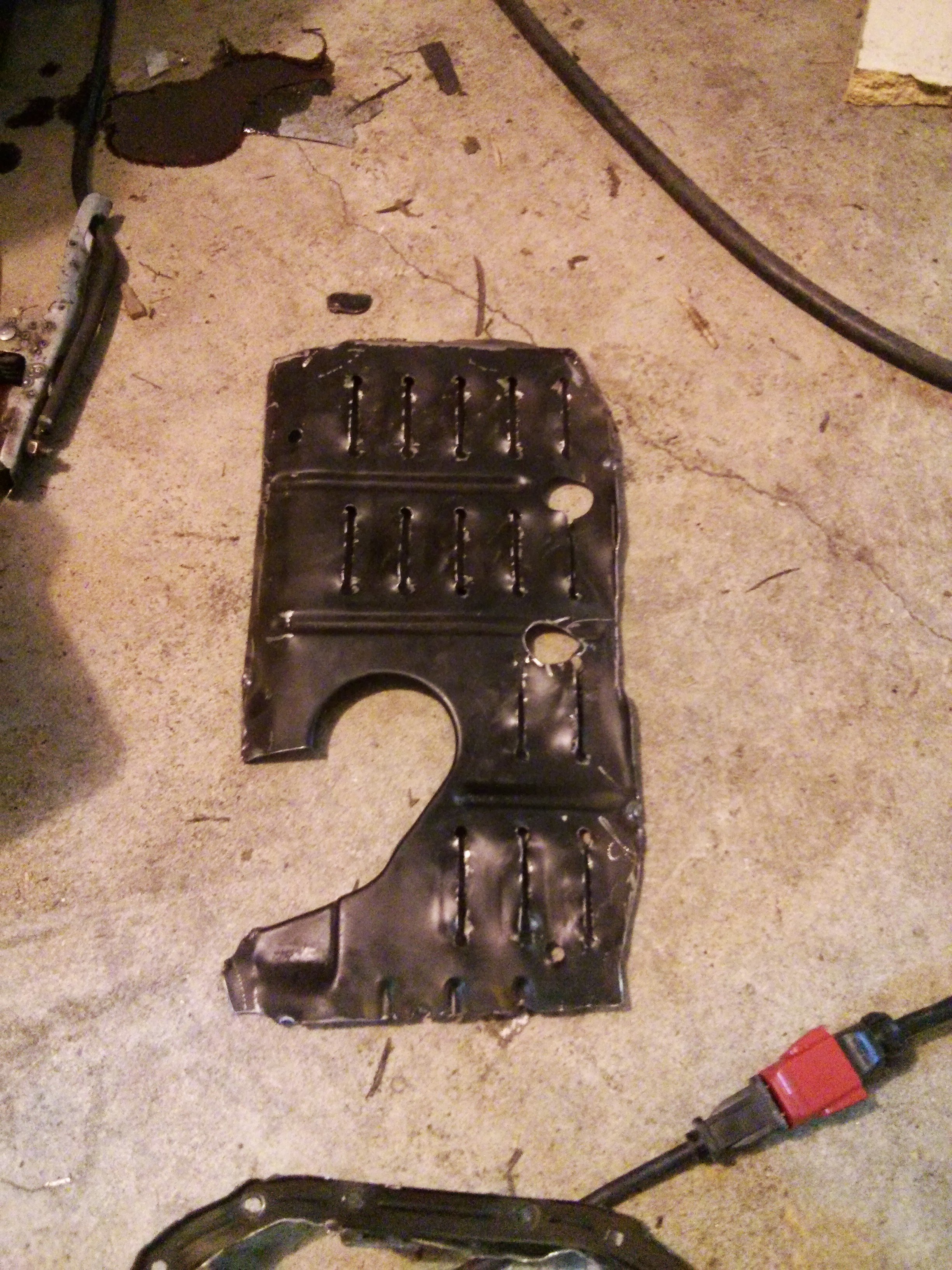
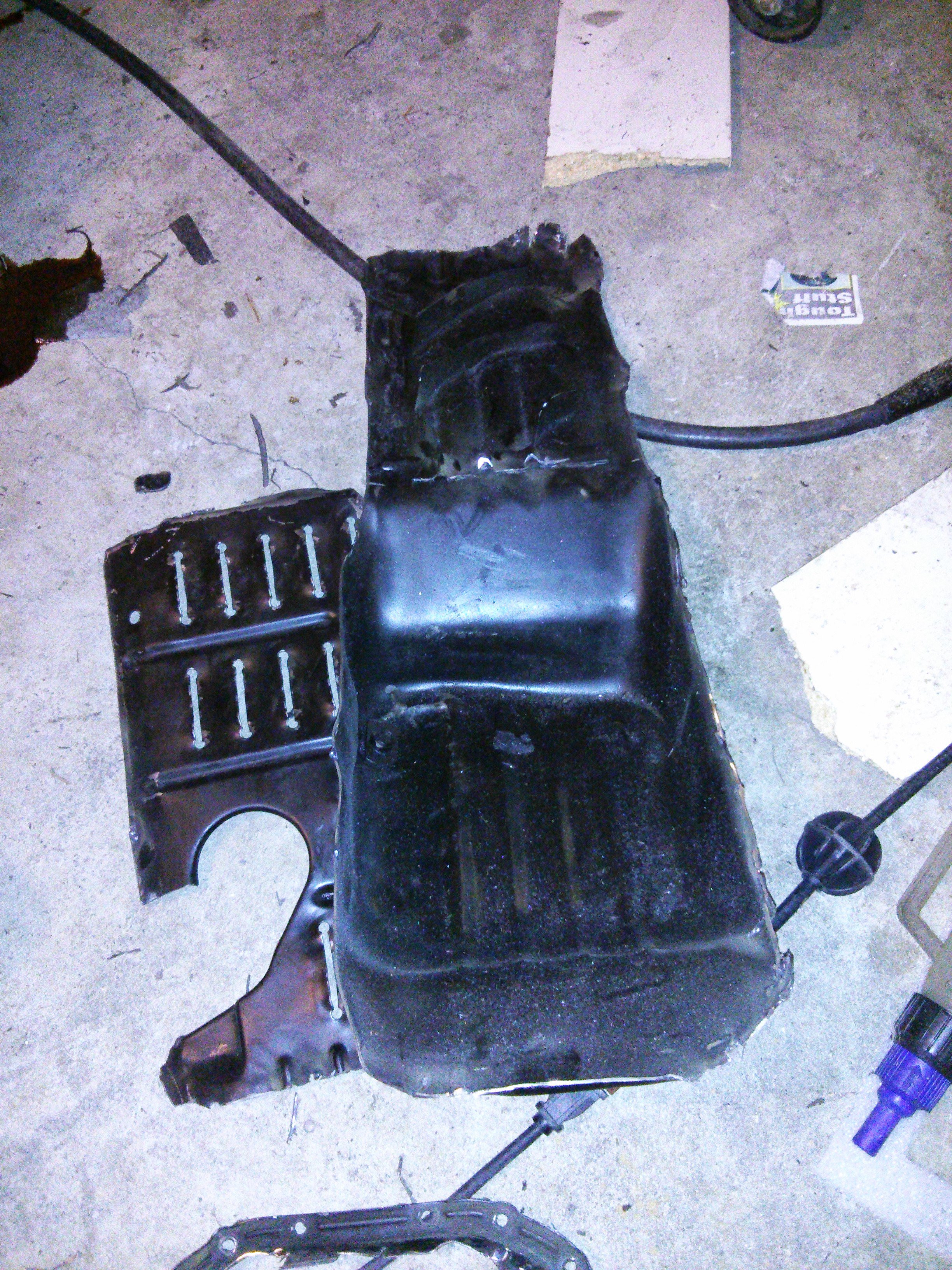
If photobucket didn't destroy my rb25 build thread, you'd see we arrived at the exact same mods (Circa Aug 2013). mine however stayed looking like your original version. Haha.
To account for the cant of the engine, I simply cut off at an angle. Windage tray I put back in as is, but bent all the louvers the opposite direction. Sump, I wish I had some fancier measuring tools. Once the welds were ground and painted, it wasn't so bad. I may remove it and add some trap doors and wings for extra capacity. All this RB oil woes makes me nervous (though I know it is mostly overblown).
Nice work on your 2nd attempt. Looks amazing.
FS: Z31T axle adapter flanges for S30 + R200. Slim design
in Parts for Sale
Posted
No longer available.
undercut by silvermine with worse product…and finding strong oe axles is becoming too challenging.