

1970 240z
-
Posts
36 -
Joined
-
Last visited
Content Type
Profiles
Forums
Blogs
Events
Gallery
Downloads
Store
Posts posted by 1970 240z
-
-
Did you reinforce the body? That's alot of pwr on these light weight and old cars
")
-
Hope I'm not too late to order
one 2XL T Shirt BlackTwo XL T shirt Black
One 2XL Hoodie Antique Cherry Red
-
For street car purposes, will the engine mounts accommodate VQ stock style (or any) rubber mounts? After market engine swap mounts I'm aware of all use poly, which adds unwanted vibration to a street car.
-
Yes I want in this go around. Do you have ladies shirts available to for my girl to wear with her Zcar?
-
Not sure if this will help you, but here is a diagram for the wiring.280zxtwireinstall.pdf
-
Thanks! I just updated my password 👍
-
juliarosario
any updates on getting your Z together, more pics
")
-
Click on the down arrow next to the word CREATE at the top right of the page, a drop menu will appear and you'll see the option to Donate.
or
-
It was back in December 2018 that I have mine repaired, but I believe it was around 150$. The coiled wires around circuit board on mine were damaged. He wasn't able to fix the fuel light at the time because he didn't have the correct Thermistor information. All he was able to get was the ford unit as described below, but ford's operate on a much lower voltage so they overheat and burn up in a Datsun.
Disclaimer: Below is what I did, if you choose to do the same or similar thing it is at your own risk. Remember that fuel and it's fumes are flammable and dangerous!
My gauge light "canister" on the sender was shot, so I bought a ford unit (I tested the fords away from the fuel and it's thermistor was too low of voltage, it burned up on the Datsun so DO NOT have it around fuel and plug it in!) , I opened up the canister and replaced it with this thermistor below, it's been working great since December 2018. Test your new Thermistor setup thoroughly before installing it into your tank just to be sure that it doesn't over heat and works properly.
I sent my Thermistor info to Bob's Speedometer, so he maybe able to fix the light in house now.
DESC: THERMISTOR NTC 1KOHM 3972K DISC Amphenol Advanced Sensors / RL2004-582-97-D1
Ford Canister:
-
Had my 77 sender repaired by:
-
Did you find the issue?
-
On 7/25/2017 at 5:05 AM, 1969honda said:
Figured I'd share this here in case anyone had missed it. It looks like the site administrators are struggling with this issue of site traffic and keeping the server current and funded.
http://forums.hybridz.org/topic/127731-hybridz-may-be-shutting-down/page-2?do=findComment&comment=1193898I saw this when it posted, that's when I decided that I have resourced so much info here and enjoyment that I was indebted to HybridZ, I immediately donated and have donated since. It is soo unfortunate that photo bucket robbed the forum of so much visual information that was present.
-
On 12/16/2018 at 1:17 PM, 1970 240z said:
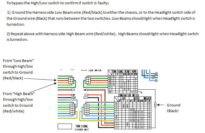
You can bypass the High/Low switch to confirm the headlight circuit is working properly.
I just pulled the dash on my 77 project and thought I'd do some headlight circuit testing. This car has the OEM style headlight bulbs. With the Key Off, Turn sign switch and headlight switch fully removed, I get no power to the fuse box as expected. I connected only the Red wire and the White/red wire to the Headlight switch. With the Headlight switch off there is no power to the fuses as expected. Turning the Headlight switch fully on and there is power to the fuses as expected. Checking the power at the round Sub-harness connector of one headlight (in this case the left side) I had power at each of the 3 wires, not expected. I realized the power is routing through the right-side bulb which is still connected. To verify I disconnected the Right-side Sub-harness, this removed power from both the Low & High Beam wires at the sub-harness connectors. I still had 1 wire with power (Red on the right & Red/yellow on the left) in each Sub-harness connector as expected as these wires are coming from each of the two fuses. At this point I reconnected both Sub-harnesses. At the column, in the 6-pin connector, I temporarily grounded the Red/black which activated the Low Beams, I moved over and then grounded the Red/white which activated the High Beams as expected. Keep in mind that I still ONLY had the Red wire and the White/red wire connected to the Headlight switch, no other wires and key was off.
See if you get the same results.
On a side note, I actually had an experience where BOTH headlights were burned out, likely from a voltage regulator issue causing over voltage. Look closely at your bulbs to ensure that you aren't having a similar issue with the High Beam circuit.
-
4 hours ago, bawfuls said:
I just checked voltage again at both the round connector sub-harness and at the headlight bulb connector, and they were the same (this is with the high beams pin on the 6-pin connector at the turn signal grounded directly to chassis). voltages on these three pins: 11.4V, 0.8V, 10.9V. That's the middle pin, the fatter one, that reads low while the other two read high, all of these are measured against chassis ground.
Voltage at the two headlight fuses are both 11.0 currently. I just checked the battery directly and it's reading 11.88V right now (lower than the ~12.4 I was seeing on Monday, I have the car "on" right now so the DC-DC converter should be recharging the 12V battery from the high voltage pack).
Voltage at the C-4 connector is 11.98V for both headlights. This is a bit funny because when I checked the voltage directly on the battery terminals immediately after this, it read 11.88V.
Verified no power at any of the sub-harness connectors for either side while the C-4 connection is open.
Still feels like a grounding issue because I only get power when I directly ground the high-beam pin at the turn signal harness as you instructed in your previous post, and I get no power at the headlights when I ground the low beam pin and put the switch to low beams.
Looking again at the schematics, there is a wire branching off of the right headlight wire after leaving the fuse to feed the High Beam Indicator bulb located in the speedometer. The ground side of the High Beam Indicator connects to the High Beam ground wire circuit (Red/white wire) "the fatter one, that reads low" so it will always have some small amount of voltage due the small amount of power passing through the bulb, so I would say your 0.8v would be expected there.
For the right head light, the Red wire should be the only wire with near full battery voltage,
For the left head light, the Red/yellow wire should be the only wire with near full battery voltage.
Interesting data collected from my 1977 with all switches connected.
Battery Voltage = 11.94v (engine & Key off).
Ltf Headlight Sub-harness connector: Rt Headlight Sub-harness connector:
High Beam: R/y=11.88v High Beam: R=11.87v
R/w=.12v (won't light a Test Light) R/w=.14v (won't light a Test Light)
R/b=.00v R/b=.00v
Low Beam: R/y=11.92v Low Beam: R=11.92v
R/w=11.92v (lights Test Light but is less bright than R/y) (likely less amps) R/w=11.92v (lights Test Light but is less bright than R) (likely less amps)
R/b=.00 R/b=.00v
I don't have a reason yet for the higher volts but lower amp 11.92v R/w on Low Beams vs .12v on High Beams, other than I'm sure it's feed back from a circuit in the switches.
I thought I would share this to see how it corresponds to your results. I am running the stock headlights though all my other lights are LED.
-
I could go for a couple of shirts and stickers too if they're offered again.
-
I suggest putting your stock headlight bulbs in until we can get both hight & low beams working correctly. That would remove the led variable from the equation.
Did you check voltage at the headlight bulb connector or at the headlight sub-harness connection (round connector) at the inner fenders? There are two Sub-harnesses, one for each headlight just on the inside of the fenders near the radiator bulk head. That round connector at the sub-harness can get tarnished and need cleaning, resulting in too much resistance.
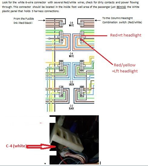
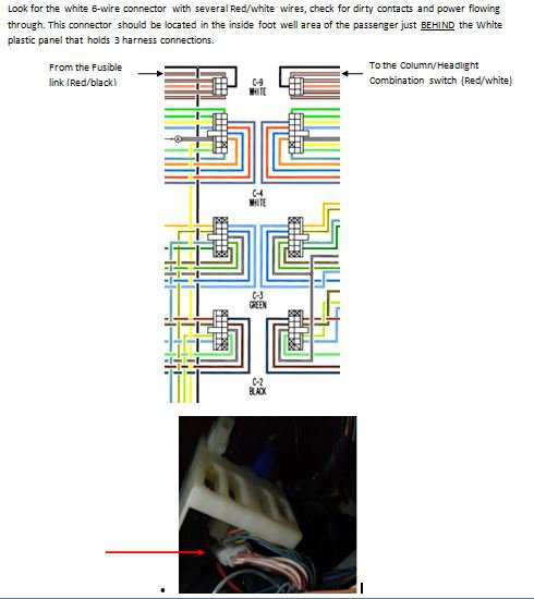
Power runs from the fuses (one for each headlight) through the C-4 (White) connector located in the passenger foot well (see pic), through the engine bay harness, then through the headlight sub-harnesses, to the headlight bulbs.
1) Clean the Fuse connections well. What is the voltage at the fuses?
2) Clean the C-4 (White) connector located behind the white mount up in the passenger foot well, check voltage here. (Red/yellow=Lft headlight & Red=Rt headlight). With this connector disconnected you should have no power to the headlight bulbs.
3) Clean the Sub-harness connections as well and check voltage. Are you getting only one 12v power source at each of the Sub-harness connectors? Each of the connectors contains two grounds (high & low beams) and one 12v (pwr from the fuse box; Red/yellow=Lft headlight & Red=Rt headlight).
4) What is voltage at each of the headlight bulb connectors after cleaning & testing through steps 1-3? Do you have multiple 12v power sources here but not at step 2?
It's normal to have a little voltage drop as we go along the harness, but it shouldn't be excessive.
Refer to the previous diagrams for wire colors as needed.
-
On 12/16/2018 at 1:17 PM, 1970 240z said:
You can bypass the High/Low switch to confirm the headlight circuit is working properly.
Lets try removing the Turn Switch out of the equation;
1) unplug the 6-wire connector from the switch but leave the Black Ground wire running between the two in tack.
Did this remove the "extra" power from the Headlight plug?
2) With the Headlights off ground the Red/black wire on the harness side (see diagram above for location).
3) Turn the Headlight Switch to the "on" position, do you have Low Beam lights?
4) If so, then the Turn Signal switch is suspect and likely needs to be opened up and have the contacts cleaned.
-
Looks really nice! I'm building another car and am considering those flares too. I can't wait to see your beauty with the wheels on to fill out the new flares!
I too went with the cut bumper when I did my car! 👍
-
-
Also, I corrected my basic troubleshooting, the fuseable link servicing the headlight switch is the outer/front fuseable link.
-
The fuse box "headlight" circuit (see diagram earlier in posts) has a White/black wire feeding to it from the Ignition relay & Fuel Injection so power could be coming from this circuit and back feeding back up to your switch if your key is "On". The High Beam position is likely providing a grounding route, the Low Beam position may have tarnished contacts and may not be completing the ground. I think we should focus on getting power to your large White/red stripe wire at the column. There is a 6 wire connector at the passenger foot area against the firewall. It is likely behind the plastic mount for the Dash harness connections, its possible this connection is dirty.
-
You can bypass the High/Low switch to confirm the headlight circuit is working properly.
-
Excellent on getting the turn signals working!
Now on to your headlights. Here is a basic troubleshoots guide I put together for someone else, I believe you have done much of this but take a moment to review it to see if anything in it helps.Here’s a sorta step by step process for checking.
1) Start by checking the Engine bay main fusible links connections. The one closest to the fender (outer) and the front (away from the firewall) is the one that provides power to the headlight switch. These often get tarnished or corroded at the Blade connectors. Once these are cleaned and you’ve verified power on each side of the connection then move to the column.
2) Check the large White/red wire at the column; this is power from the main fusible links. This is where power enters your switch. When the switch is turned on, power exits the switch to the fuse box by way of the large Red wire with the bullet connection. At the fuse box the power is split into 2 circuits, one for each headlight.
3) Check for power at the two headlight fuses and ensure the fuses to the fuse-box connections are clean and good.
4) Since both headlights are affected, it’s not likely that these two separate power-circuits to the headlight bulbs are the issue.
5) The headlights share two common ground circuits, one for Low beam & one for High beam. Since both high & low beams are affected it is not likely these individual ground circuits from headlights back to the Turn Signal switch (High/Low selector).
6) There is a wire at the column that connects the Turn signal switch (High/Low selector) to the Headlight combo switch. Check that connection; this is where the ground circuit routes to the Head Light switch, which then continues out the large Black wire with the Blade connector to ground.
There is no factory relay in the headlight circuit. There are aftermarket kits or people modify to add a relay. If yours has this mod. then the wiring and relay for this could be a suspect as well.-
 1
1
-
-
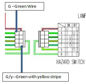
For a 1977 280z:
To bypass the Hazard switch to allow you turn signals to work, Jumper (on the harness side) the Green wire to the Green/yellow wire. If your turn signals work after applying the jumper then you know the Hazard Switch is an issue and not working, it likely will need to be rebuilt or replaced. Usually the contacts inside the switch are dirty and need to be cleaned.

HybridZ Apparel Order Thread - 100% of Profits Will Be Donated, round 5
in Vendor's Forum
Posted
Glad to hear they are shipping, can't show off our new threads if we don't have them.
Lol 😆