JoeK
-
Posts
263 -
Joined
-
Last visited
-
Days Won
2
Content Type
Profiles
Forums
Blogs
Events
Gallery
Downloads
Store
Everything posted by JoeK
-
Looks great. What size are the accessory gauges?
-
I'm believe you only have to align the seam on the caliper with the center of the rotor. The pads can easily be off center. It looks like you are close enough.
-
One of these may work. I'll PM you.
-
Quarterly bump
-

Slow Build 240Z LS1/MN12 - Build Thread
JoeK replied to JoeK's topic in Gen III & IV Chevy V8Z Tech Board
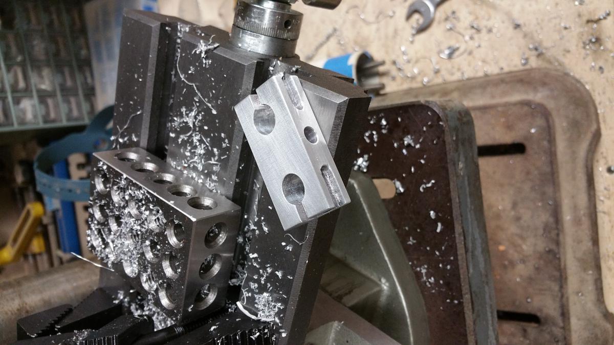
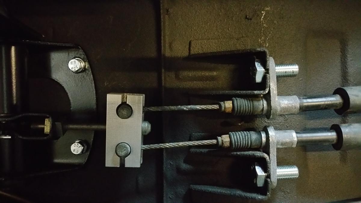
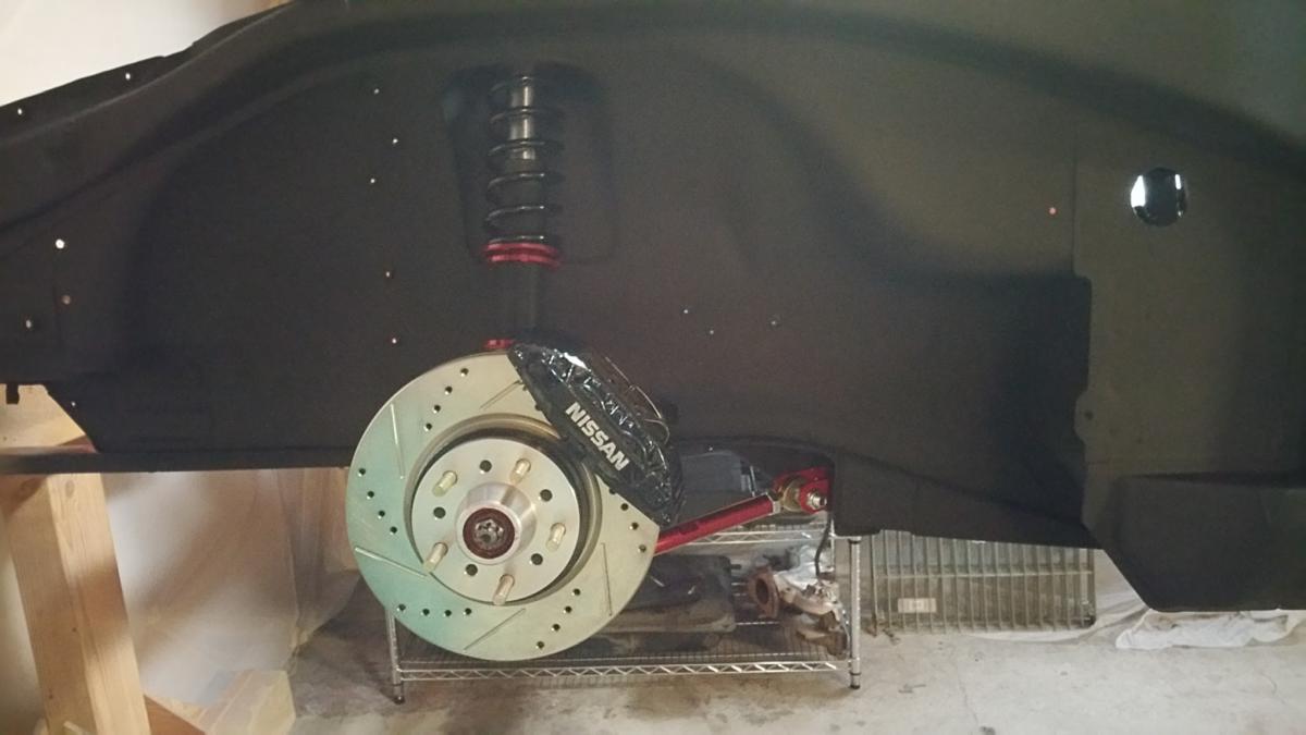
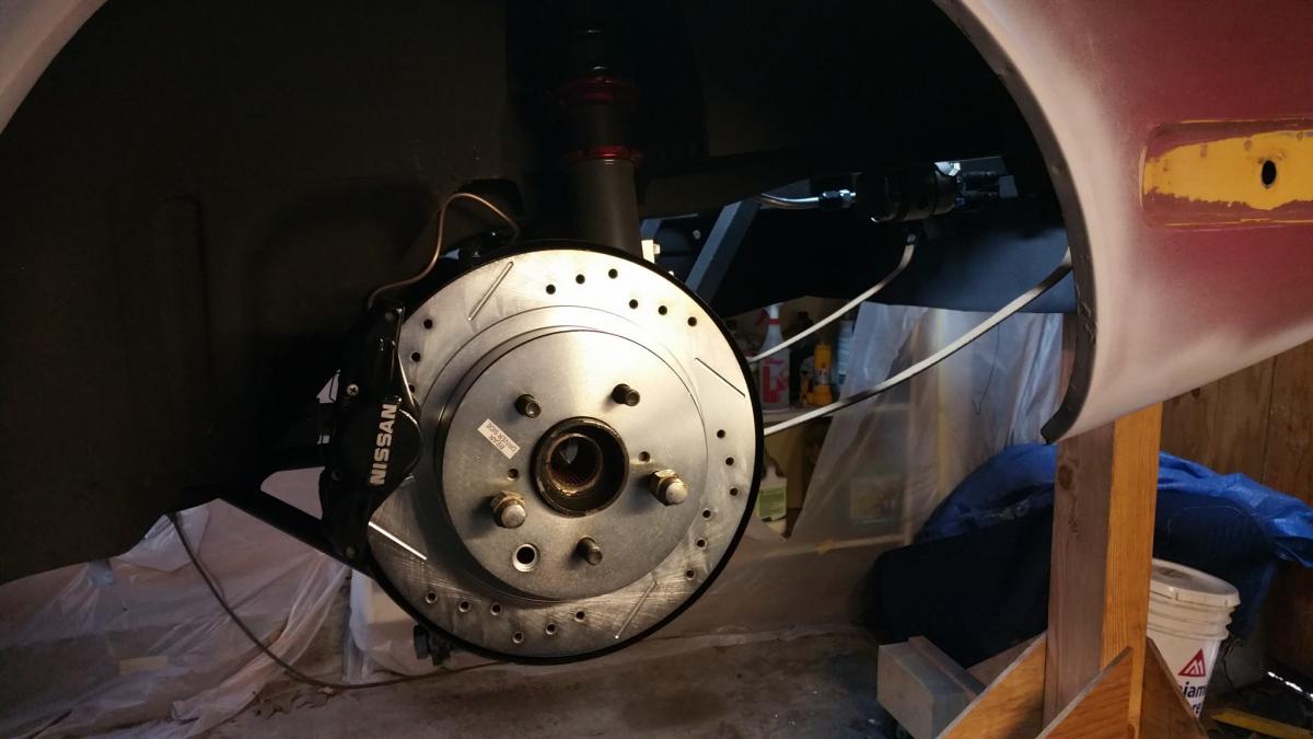
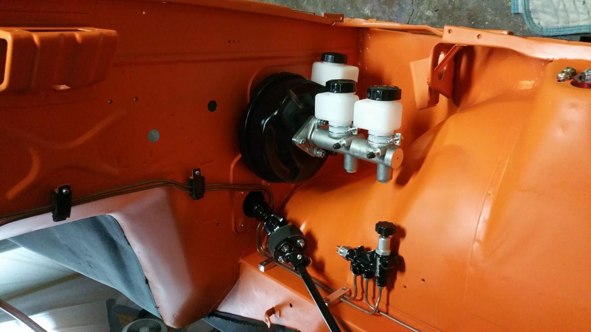
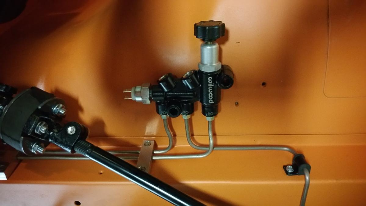
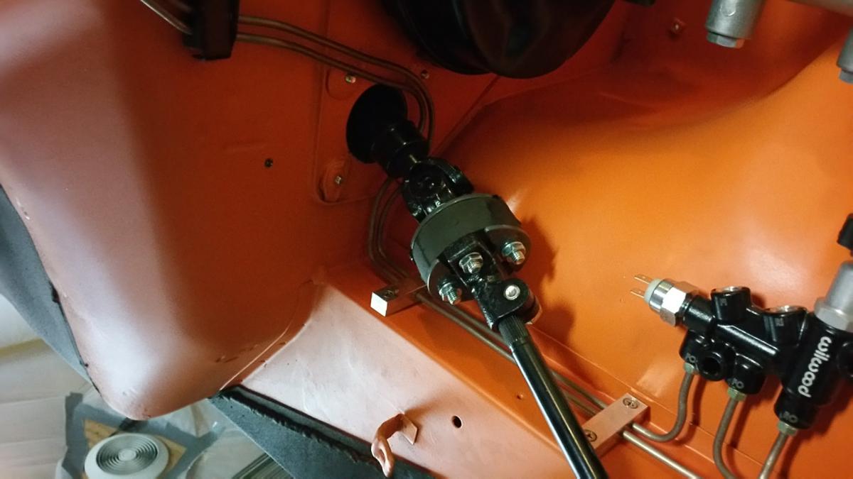
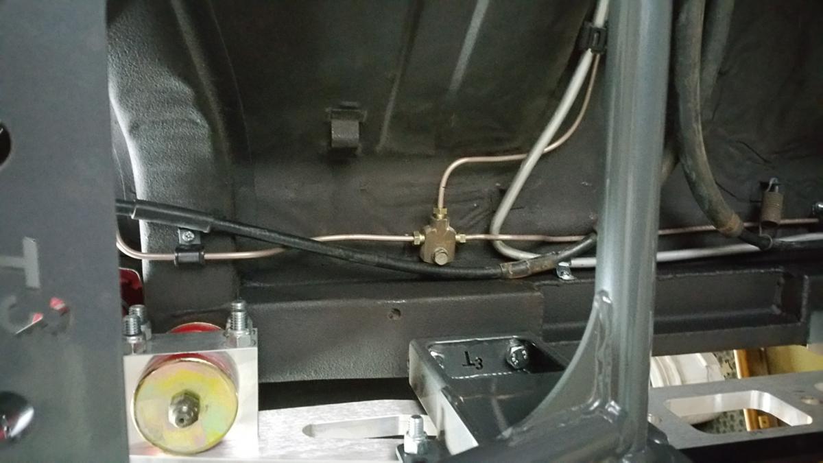
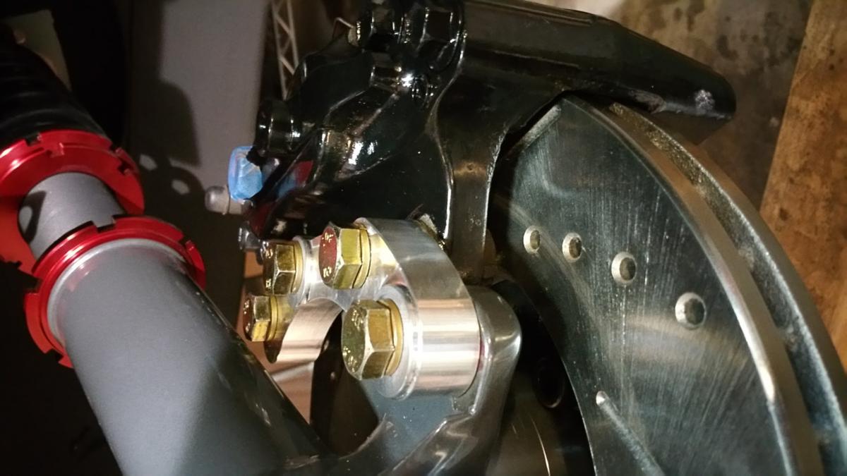
Just about finished up the brakes system. Just a little bit more plumbing to do, fabricate the lines from the Master Cylinder to the Proportioning valve, and flare the ends if the front lines. Waiting until I get wheels to make sure the flex brake lines won't interfere, then I'll know which fitting size to put on the flared ends. But I went ahead and replaced all of the brake line with new hand bent Fedhill line, Wilwood Master Cylinder and combo proportioning valve/splitter. Got Z32 brake adapters from Arif. Needed to make do some minor clearancing to the calipers, since my hubs were 240z copies. Was some very minor grinding where the caliper hit the mounting ear, nothing a quick hit with a rotary file didn't take care if in a few minutes. I did end up having the Odyssey rotors machined for this set up. I had hoped to use the Wilwood rotor adapters and rotors, but the adapters turned out to have a different bolt pattern than the hubs, so that plan was scrapped. Then I designed new rotor adapters and got pricing from some CNC machinists. That came out to about $350 per side, so that plan as scrapped as well. Happy with the Z32 set up, as it is now, just hope I don't have to replace the rotors anytime soon. The TTT R230 swap set is nice, but doesn't come with a way to attach the parking brake lines. If I was smart enough to grab the front parking brake cable from the parts car, I think you can slightly modify the bracket on the end to attach the rear brake cables to. But I didn't have that part and couldn't find it used for less then $50. It's just a bent piece of metal, and I can be stubborn, so I decided to make my own. This of course involved me converting an old drill press I had lying around into a vertical mill of sorts. Of course that ended up costing a few hundred bucks in tooling by the time I was done, but now I have that tool to use and play with.
-
Flipping the adapters and adding the washer totals about 5mm difference
-
If you could just get the hat height of the R33 rotor, it could be compared the odyssey rotor and you'd know the difference. I could tell you hub thickness of the 240z hub, someone else coud measure the 260/280z hub, and bingo.
-
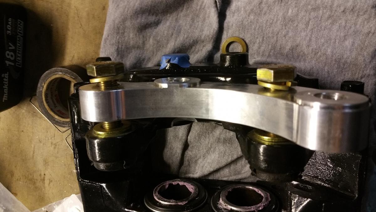
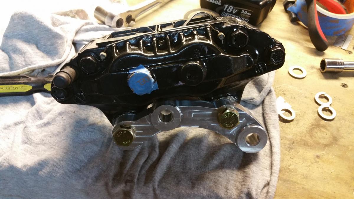
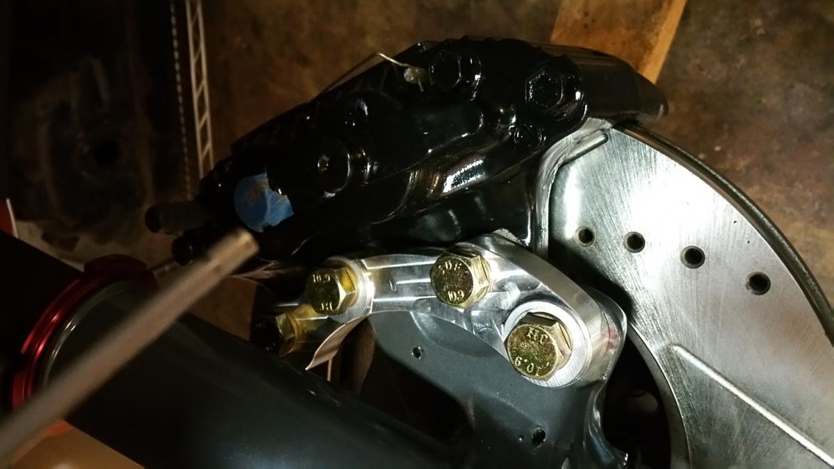
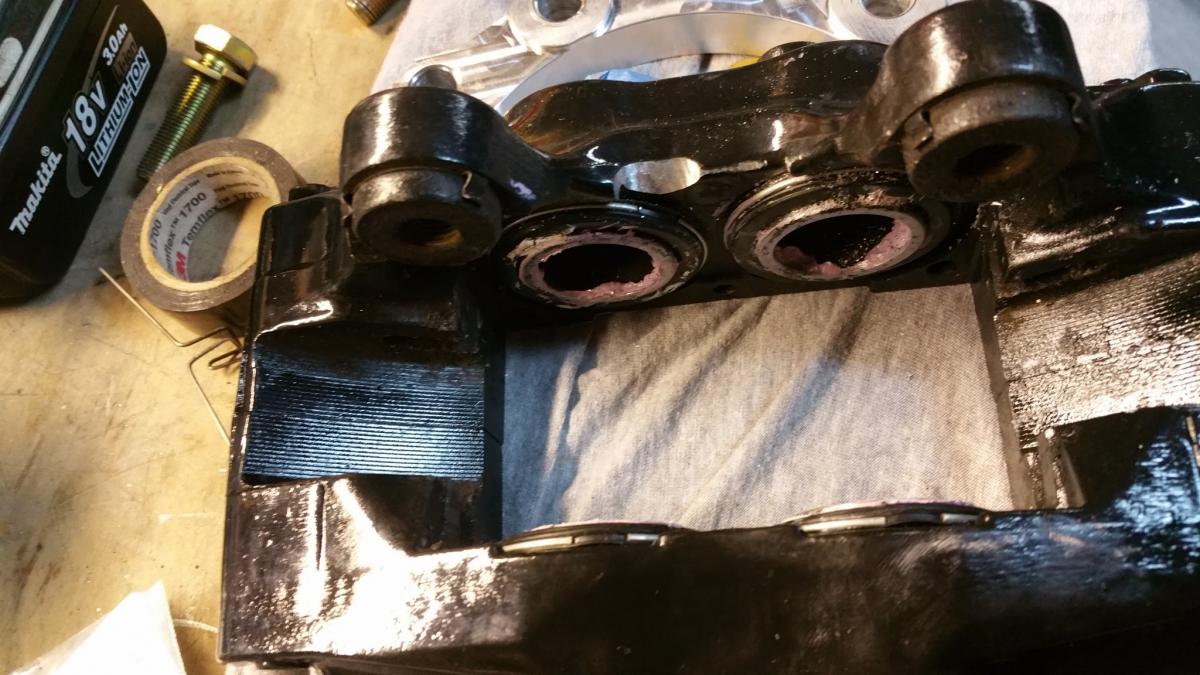
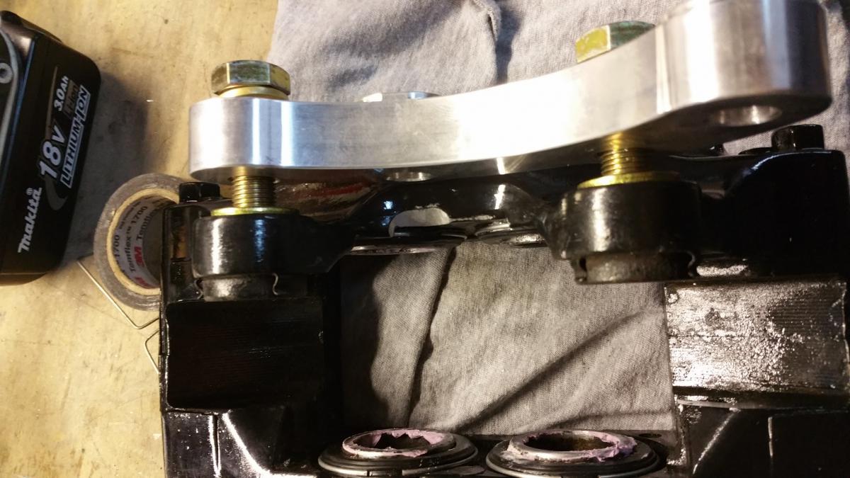
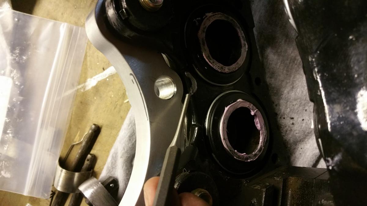
Yes, I have found that the adapter brackets were designed to be used with 260/280Z hubs. Not a big deal, but it did turn out be a little more than just washers between the caliper and adapter bracket. I had the clearance the caliper a little, but being aluminum, it was pretty easy. But here they are installed. Place a single washer between the caliper and bracket. I used 12x1.25x45mm bolts, with a lock washer between the bolt head and the adapter, to bolt the adapter bracket to the caliper. I found that adding a lock washer behind the 12x1.25x35mm bolt that came with the kit makes it the perfect length to mount the caliper bracket to the spindle ears. See the pictures and let me know if you have any questions. The last 2 pictures show what needs to be clearance, and the two before them show it clearanced. It's not much, but it rubs on the spindle ear.
-
Hawks Motor & Trans Mounts - Install with Pics!
JoeK replied to MECH-E's topic in Gen III & IV Chevy V8Z Tech Board
I'm pretty you do want the steering rack clamp, to keep the rack from rotating. I read that somewhere when researching rebuilding my rack. It could probably be relocated easily enough though. -
New Techno Toy Tuning Big Rear Brake Kit!
JoeK replied to Turbo6.0's topic in Brakes, Wheels, Suspension and Chassis
I thought we wanted the bleeder screw at the top, so air bubbles would escape easier. Do I have that backwards? -
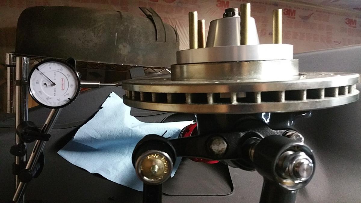
How much radial rotor runout is acceptable?
JoeK replied to jt1's topic in Brakes, Wheels, Suspension and Chassis
I've got .003 run-out in the lateral direction, measuring the face of the rotor. Radial run-out I believe refers to what you'd measure on the edge of the rotor. Basically, my rotor isn't centered on the hub properly. I had new rotors drilled, and the machinist didn't get it centered perfectly. I don't know if this is enough to cause some weight distribution, or balancing issues. Measured like this:
-
How much radial rotor runout is acceptable?
JoeK replied to jt1's topic in Brakes, Wheels, Suspension and Chassis
Bringing this one back from the deep. But don't really see an answer. I have radial runout of .090. Is there any standard? -
I got mine last night too. I was hoping to post installed pics, but decided to paint the rotor centers to prevent rust where it was cut and redrilled. Parts look real nice.
-
Awesome! I just picked up my modified rotors this afternoon too.
-
LS3 - Need to buy a stater and alternator
JoeK replied to cooperma's topic in Gen III & IV Chevy V8Z Tech Board
Like the color. Is there a reason you don't want to just run the stock units? -
Looks good. Once you have it up, tieing the front and back together makes it feel a lot sturdier when moving it around. Even a simple doug fir 2x4 bolted to the bottom tube would be fine. Speaking of getting the car up in the air, do you have a plan for that yet? When I did mine, I used an engine hoist in the front (which worked great) and come alongs in the back (which was kinda sketchy). I think I'm gonna find someone to loan me another engine hoist, so I can just use one on each end.
-
Welding the horizontal bar in, or side to side bar, that the front to back bars then mount to seems like a good idea to me. Reason being, if your adding bars just front to back, from the rear cross member to the back of the car, any rear end accident you might encounter, the force gets transferred directly to the rear cross member that your rear suspension is mounted to. Could pretty quickly total a car that may have otherwise survived. That was the thinking anyway in building the Camaro tank support in my S30.
-
Wish I had thought of it at the time, but the differential cross member could theoretically be cut apart. All you need are the sections that holds the control arms, since the diff now mounts differently. I had that crossmember, as well as the rear RCA clips, powdercoated the same color as the rest of the TTT parts. after which I figured out I could cut that middle section out of the crossmember and it wouldn't impede driveshaft install, or even install/removal of the diff itself. As far as parts I wish the kit came with, it would be nice if it came with some hardware to connect the parking brake cables to the parking brake lever assembly. Gonna have to fabricate up a little bracket for that.
-
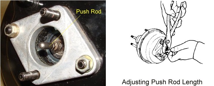
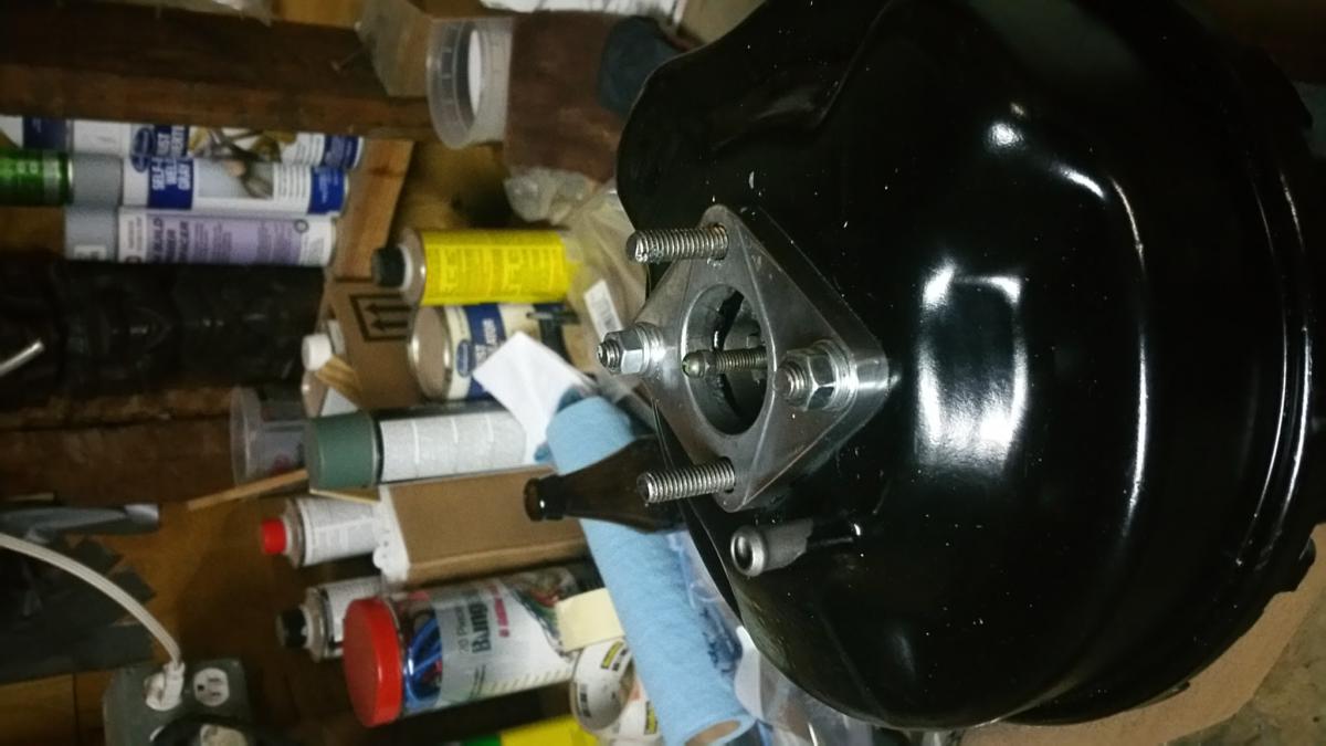
As opposed to this pic, where the pushrod looks different than mine. This pic is from the first post in this thread.
-
I'm working on this swap. New booster from a '78 280z. The pushrod appears to be too short. I the pic below, it is about right where I want it to be, about 12.5mm from the face of the aluminum spacer, but it is only threaded in 2 1/2 turns. I pulled the pushrod out of my old booster and it's the same length. The pictures some people have posted in this thread that show the pushrod, they look different than both of mine. They seem to have 1/2" or more length in front of the nut. Suggestions?
-
Payment sent
-
What would the advantage of a hydraulic set up be?
-
Looking good. It looks like TTT redesigned their drop mounts. Are those aluminum now? Did your Q45 drop out come with the parking brake cables?
-
I'm in for a set. I still havent found anyone to mill the rotors, but since everyione seems to be having no issues, I'll assume I'll find someone eventually. Or I'll ship the rotors to one of the machinists that have done this for you guys. I do have the TTT 5 lug hubs, but their machinist wouldn't cut the rotors, Gabriel said the job was too small. Gabriel did send me a pdf of the patterm on the back of the hub though.
-
Stock Car Mafia's '78 280z LS2 Build
JoeK replied to Stock Car Mafia's topic in S30 Series - 240z, 260z, 280z
Ha, I'm in the middle of a 2.5 week vacation in Cambodia of all places, on a beautiful secluded beach, and really looking forward to getting home and back to work on the car, haha