inline6
-
Posts
453 -
Joined
-
Last visited
-
Days Won
3
Content Type
Profiles
Forums
Blogs
Events
Gallery
Downloads
Store
Everything posted by inline6
-
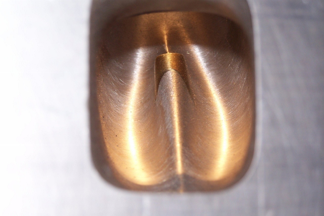
My engine builder sent me this pic. We had been discussing how bad the L series ports are in general and I pointed out that the japanese head pics I had seen showed the porting done with out the guides, and the guides installed afterwards. He laughed and called that "lazy" and "wrong". Here is a pic of one of the heads banging around in his shop - it's from a NASCAR engine. I thought it pretty awesome.

-
Been searching, reading, etc. Might go a different direction. I am thinking of building a 3.3 L stroker instead of what I had. I am still investigating, but it looks promising. We'll see.
-
The titanium valves are really a separate issue. Through my engine builder, I've been in contact with the guy that developed the Sunbelt cam I am running, and it wasn't known by me until now that the cam and valve spring set up I am using was designed to utilize titanium valves. So, just going to do that. The blown engine was not related to running the stainless valves.
-
Saw this racing seat in Mark Rolston's latest car. Sure is nice: Tillet B1... bit pricey though huh?
-
I'm running an e88 head and need to source some titanium valves. Anyone know of any that are out there, or do I need to look at custom at this point? I believe David Weber of Malvern Racing told me at one point that he was reusing (after mods) some NASCAR valves... I recall him saying they only ran them one race. Guess I'll start scanning the available titanium valves for ones that are close to the stock Nissan size I need. Looks like Del West and Ferrea will do custom, but that is typically a synonym for EXPENSIVE - as in even more expensive than titanium are already going to be.
-
Thanks for the info - I appreciate it. I will get weights of the valves and relevant hardware. Logic tells me that the smaller exhaust valves will weigh less than the intakes. On that basis, we'll see how much the new exhaust valves weigh in stainless vs. the intakes in titanium. Sourcing titanium valves isn't exactly easy, I guess, as I just spent a few minutes looking on the web... If only I could know... I have a lot of anxiety over building essentially the same engine again as the harmonics, if the problem, may wreak havoc to it again. If only I could get it tested on a dyno after it is built and tune the damper, or change whatever else as necessary (smaller flywheel) to know that I will not have a harmonics issue in an important rpm range... (again?).
-
Need one Mikuni 44 phh - parts carb ok, but need good body.
inline6 replied to inline6's topic in Parts Wanted
bumping this for another try. -
Since I thoroughly trashed my "new" engine at Road Atlanta, I now need to build another. The "new" engine was fun while it lasted - a total of 3 and half 20 min sessions... but that limited longevity wasn't what I was after. The head appears to be ok, but will be checked out thoroughly. The cam no longer will spin in the towers like it did - it spins by hand but keeps hanging up a bit in the same spot of each revolution. Since there was piston contact to one exhaust valve which bent the valve and knocked a rocker off, perhaps the cam is bent. It will be checked and replaced if necessary. Some things that I have been thinking about: Why did the "new" motor blow up? Basically, it looks like the #1 and #2 main cap bolts backed off while the engine was operating. This cause oil pressure loss to the bottom end. The number #2 rod bearing experienced a metal forging process until it was many times thinner than when originally manufactured, then the #2 rod cap broke in half, the rod bolts broke, the #2 rod broke off below the piston pin... and this middle section of rod #2 then found its way into the path of rod #1, etc. etc. The main bolts were torqued to 45 ft lbs. Factory spec was looked up at the time the engine was built (I think it was 43). My engine builder was very concerned about such a light torque spec with those bolts - he was concerned about adequate bolt stretch. He told me so when the engine was built. To attempt to address, we will be replacing the stock bolts with ARP hardware. So, why did the main bolts back out? I really don't know. The rest of the main bolts were tight at the time of inspection and dissembly. The #2 bolts were both so loose that I removed them by hand. #1 had just enough torque that a wrench was needed to un-clock them about 10 degrees before I could remove them with my fingers. If I am guessing, then possibly harmonics/resonance of the crankshaft came into play. Another piece of evidence that I think points to this are the flywheel bolts: I have no idea what caused 4 of the 6 to collect a couple of crankshaft threads at the end of the bolts... and weld all that shite together. It made for no fun removing them. It is interesting to me that only the last 1/8 of an inch of the bolts was affected for four of them and two were essentially ok. If it matters, there were some rather unusual driveline forces in play when, at north of 6500 rpm, most of rod #2 broke away from below the piston pin and got caught in between the big end of rod #1 and the block. This LOCKED the engine completely at just north of 100 MPH. Could going from high-ish RPM to NO RPM in a split second... in conjunction with a 2500 lb car on sticky race tires have yanked the flywheel so as to cause this to happen with the flywheel bolts? I am doubtful. What if it is a harmonic issue? Well, who can run their L series between 7000 and 8000 RPM then? I've read in many posts that running in the 7300-7500 RPM range is a problem and it is to be avoided with these engines. Even with an 8k or higher cam, depending on the track, won't there will be significant amounts of time spent per lap between 7300 and 7500? Must we all build the 6 cyl L to rev no higher than 7200 RPM? Or, must we all go salt flat racing where we turn 9000 RPM plus, so we never dwell in the evil zone for longer than a fraction of a tic of the second hand? The current plan: I have sourced two N42/N42 engines which the engine builder will retrieve on Monday. The plan, for now, is to build the engine nearly the same as before with at least these changes: ARP main studs will be used instead of the stock bolts When I have the crankshaft offset ground, I may not have it lightened this time. From what I have been able to determine, the Rebello BHJ damper I am running was tuned for an L-28 stroker crank. More research will be done so I can understand how best to proceed. I think it is possible to have BHJ tune a damper for an engine on a dyno. I will look into this. Dry sump oiling system - I believe it was Clarkspeed who said he was running a Nismo comp. pan and his Accusump was working in turns 6 and 7 of Road Atlanta. I don't have an Accusump, and my Nismo comp pan was damaged quite a bit when the rods let go. Since I don't really know the cause of my engine failure (perhaps I was just getting oil sling away from the sump causing oil starvation and main caps #1 and #2 came loose after the grenade went off inside the front of my engine), going dry sump seems wise in retrospect. An Electromotive Tec GT and TWM fuel injection set up will be used instead of the Mikuni 44 set up. I couldn't get the jetting to do what I wanted with my cam and the distributor with Crane HI 6 and optical pick up was still indicating some spark timing irregularity above 7k or so rpm. Going distributorless will allow me to move the rev limit up to the full 7700 RPM spec'd for the cam. At least at Road Atlanta, a 7700 RPM limit may have me spending less time in the evil RPM zone as the Hi 6 was holding me at a 7400 RPM limit on the back straight for a while before I would brake for turn 10a. The cam I am running was developed with titanium valves. The intakes valves will be switched from stainless to titanium but I will again run the stainless exhausts for durability. That's where I am for now. I'm sure things will change a bit as we go... It's too bad I can only devote part of my time and efforts to my hobby. That makes the learning come slower and at a much higher cost.
-
Bad car stuff always happens to me in twos or threes. I was telling this to my co-workers the Friday before I went to the track. The day before, a guy in a Ford Expedition that works in the same building didn't see my Honda S2000 parked next to him in the parking lot, cut hard and punched the throttle getting out of his space... hit the poor thing, shifting the front over a foot and a half to the side (I was backed in). He never stopped, just hit it and knocked it out of the way as he exited his space. He did come tell me... but jeeez. For a parking lot fender bender, it was innnnnsaaaaaannnnne. I told my coworkers that I fully expected a catastrophic engine failure that weekend. And this is certainly the worst I've ever seen.
-
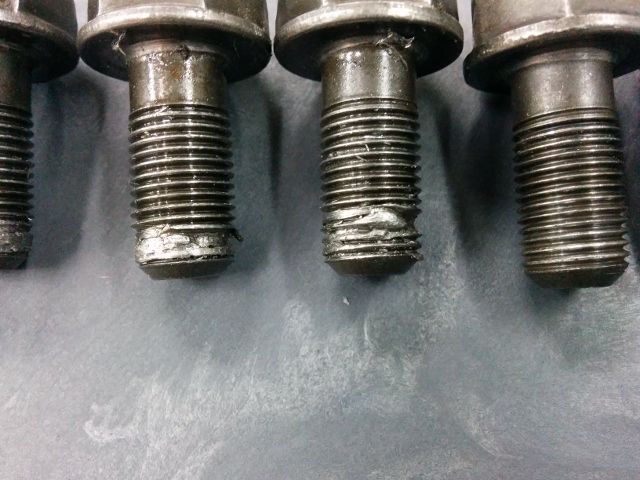
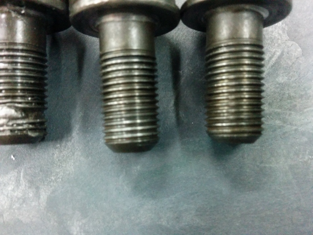
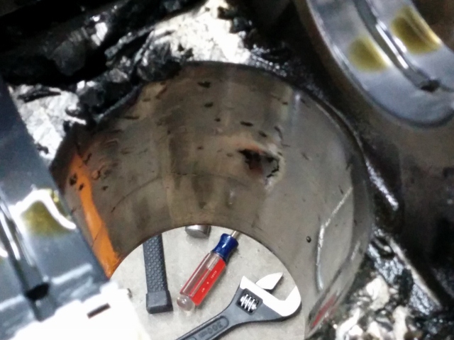
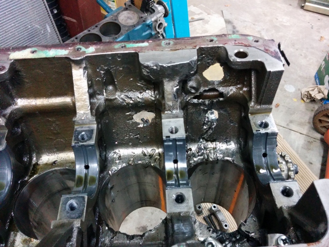
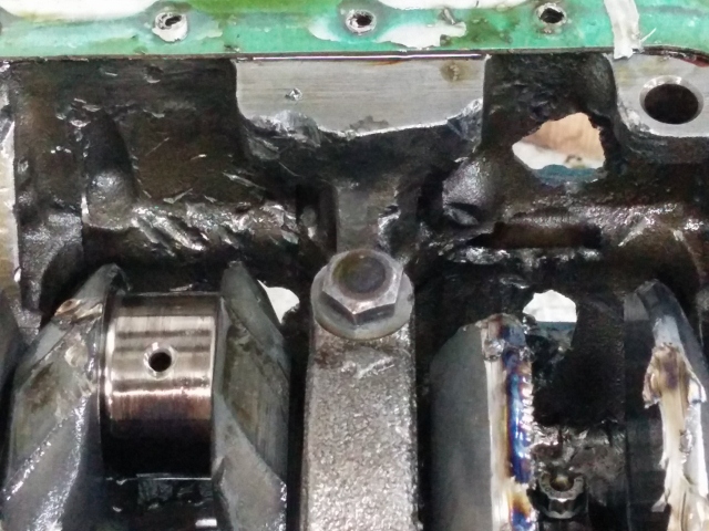
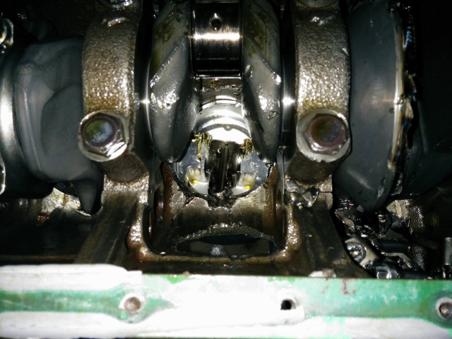
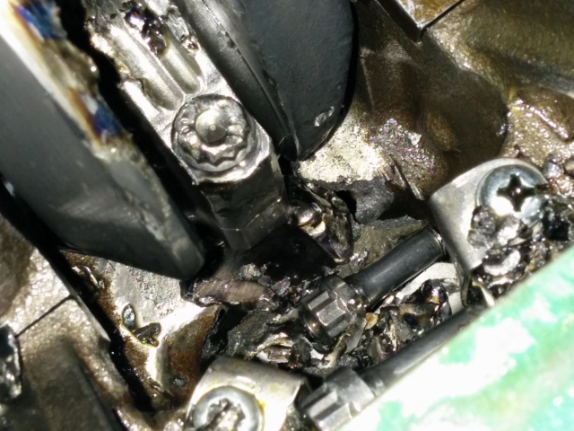
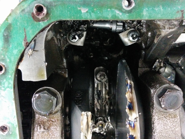
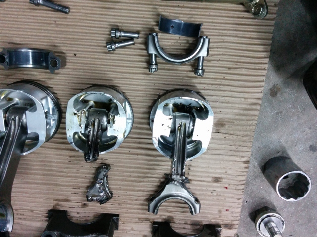
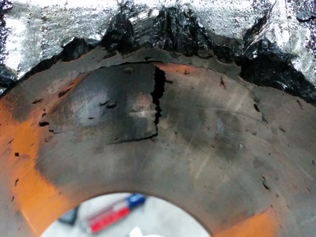
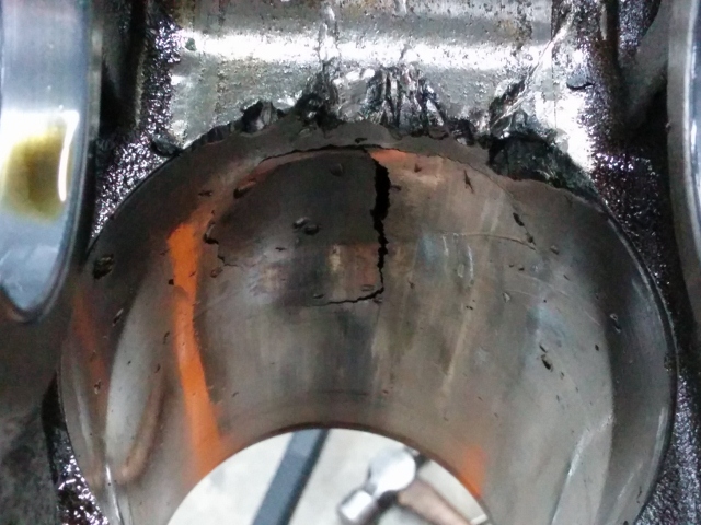
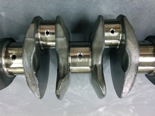
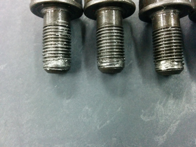
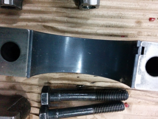
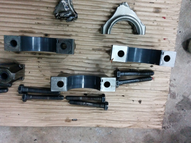
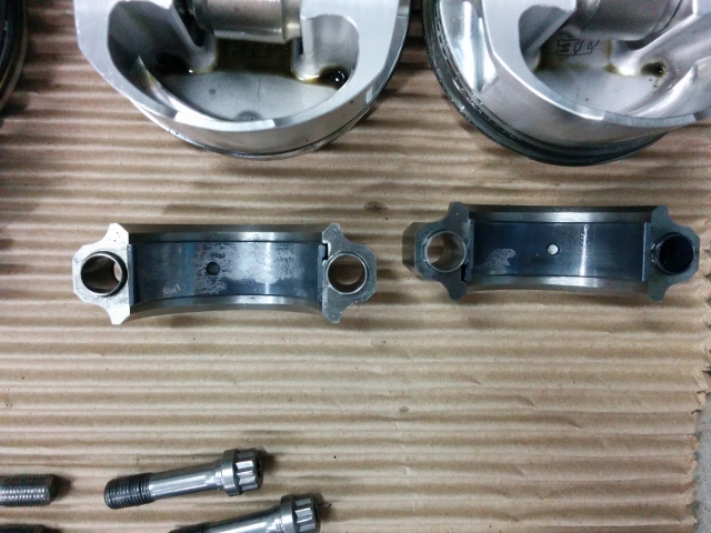
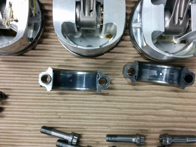
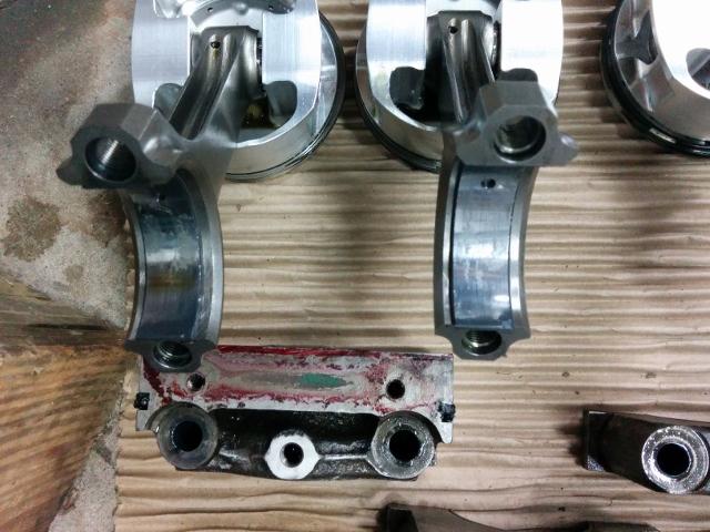
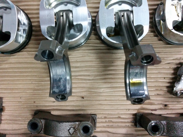
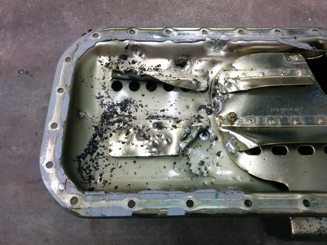
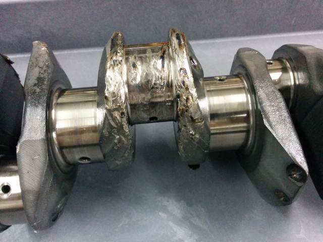
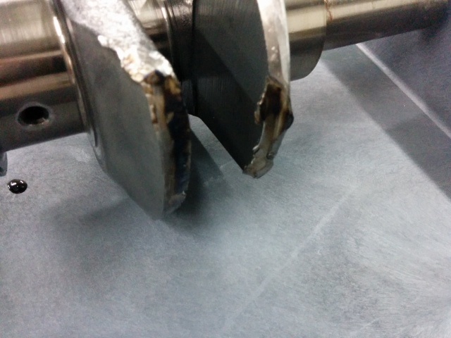
I pulled the engine out and apart this weekend. When I started to unscrew the main bolts (I used stock ones) the number one main bolts had next to no torque. The number two had none - they were already loose and I removed them by unscrewing with my fingers. My guess is that the 7200-7300 rpm harmonic that is a known issue with these engines caused the number 1 and 2 main bolts to come loose... excessive clearance in the #2 main caused a loss of oil pressure to the number two rod. That bearing disintegrated, heat generated quickly and caused the #2 rod to fail. It looks to me like the cap and rod bolts failed first. The bolts both broke and the cap split into two pieces. I found one of them on top of the driver side frame rail. Then the middle section of rod #2 got caught up against the block, and sheared off near the piston pin. This chunk of #2 rod then found its way between the number #1 rod and the block instantly locking up the engine, not allowing even 1 degree of crank rotation in either direction until I freed it up today. The #1 rod broke also but not at the bolts. It broke in the I beam section. Ok, here are a bunch of pics of the carnage: Pass. side of block - 3 holes - one behind alt. bracket: Driver side of block: Section of rod #2 caught under rod #1: #2: #2: Main oil galley taken out by #1: #2 left, #1 right: Oil pan schrapnel: #2 and #1 - crank removed: #2 bore: #1 bore: #2 bore: #1 bore: #2 bore: #1 bore: #1 main bearing: #2 main bearing: What's left of rods: #2 rod section that ended up pinned by #1 rod journal to block: Other rod bearing starting to show problems: #1 main bearing: Crankshaft bolts friction welded? What the crank should look like: Crank damage: Oil pan damage:
-
I scoured the internet for 3 days looking for info. There wasn't much beyond a few posts about the oil from the blown engine causing this. At times over those days, I felt really bad. Then I came across a post from the same guy. Since he seemed to be close to the family and helped load the car the next day, and he was saying it was a mechanical failure, I wondered if he was privy to info that wasn't public. I have to admit, it did make me feel a lot better. No one wants to be the cause of someone losing control at the track and losing their life. The most important thing I learned from this is that anything can happen... What if at my next track day event, someone blows and engine and puts a bunch of oil on the track... and I am the next car to come through? The best way to minimize injury or death from "the anything" is to install as much high quality safety equipment as possible.
-
Jim said the there was no safety equipment in the car other than stock. As it is now, I only have a four point harness and roll bar. That's really not sufficient in my mind anymore for track day safety needs.
-
It must have dropped, but I'm not sure why it would? I am running the DP Racing oil pan which is the same as the Nissan Competition pan. That one is pretty proven from my understanding. And I actually did check oil level before he last run - it was about 1/16th below the H mark on the stick. Also, my car handles ok, but the suspension is not dialed in (unless by accident) and I'm no Mario Andretti either. I was running on 4 year old VictoRacer V700s - so not street tires. Going down the back straight, I heard a "shhhhh" noise for a second or two. i glanced down at temp and oil (my car is a series I, so this is the same as my gauge). Temp needle was about a quarter inch passed the non-labeled mark in the middle, as it had been for the previous sessions. The oil pressure was a bit to the left of the middle mark. As soon as I looked back out the windshield, the engine let go. The problem, in my opinion, is my stock gauge reacts pretty slowly to oil pressure changes, at least judging by watching it at start up. This time around, it will be mandatory to upgrade all of the gauges, and to add an oil pressure light such as this: https://www.pegasusautoracing.com/productdetails.asp?RecID=1855. Jim Pantas, the director of NASA South East left a message for me to call him. On the call, I found out that the Mustang driver passed away. Jim told me that there wasn't much oil on the track. They went looking for it to put sta-dry down and there just wasn't that much. There was also some in car video from a car behind him and they had viewed it to try to determine what happened. They aren't sure, but he said it looked like something on the car broke because of how sharply it veered to the left. I dunno. I feel terrible. But, there were 12 or 13 cars that came through there before he did and they didn't have any problems... meh... this just sucks. Additional safety equipment beyond my harness and roll bar is on my ever growing list now. Probably looking at racing seats instead of the BMW seats I have now, and a Hans device at the least.
-
My new engine expired during the last session of the day yesterday at Road Atlanta. It had run 3 prior sessions and was most of the way through the last. I was going down the long back straight. I'll be pulling it out and examining it when I can in the next few weeks to see if anything is salvageable. I have two small holes in the block on the passenger side - looks like rod #2 let go. Here are a couple of video clips. I apologize in advance for the horrible sound quality - my cell phone mic sucks. I was using a driving recorder app called "caroo free". It's not a good choice for track days because it chops the video up into 20 sec snippets, but it does record some gps related info, and if you have an obd-II car, I understand you can add some car specific data to the video also. Anyway, these first two are from the previous lap in the same area - the long back straight. https://www.youtube.com/watch?v=x2Pnqk9RMQ8 https://www.youtube.com/watch?v=ekXNkr2dgi0 And these three lead up to and include when it happened: https://www.youtube.com/watch?v=Q4SveDFs1jo https://www.youtube.com/watch?v=oUMRzc6TWgk https://www.youtube.com/watch?v=hvEFJtsWnek It was my first track day event in 5 years as the car was off the road for a very long time, mainly for the engine build and a move from VA to GA. I really don't want to wait very long again, because I'd prefer to drive the car rather than look at it. I want to keep the inline 6. I don't think the current engine was "all that crazy" of a build, so I don't think that the specs of my build are inherently a problem. The short block has the same parts as Rebello 3.0. The cylinder head featured a Kinetic Sunbelt cam and valve spring set up with titanium retainers (with stainless nissan comp valves). I'll hopefully be able to pinpoint the cause as I take it apart.
-
New Set Up for Cooling Front Brakes
inline6 posted a topic in Brakes, Wheels, Suspension and Chassis
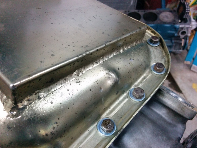
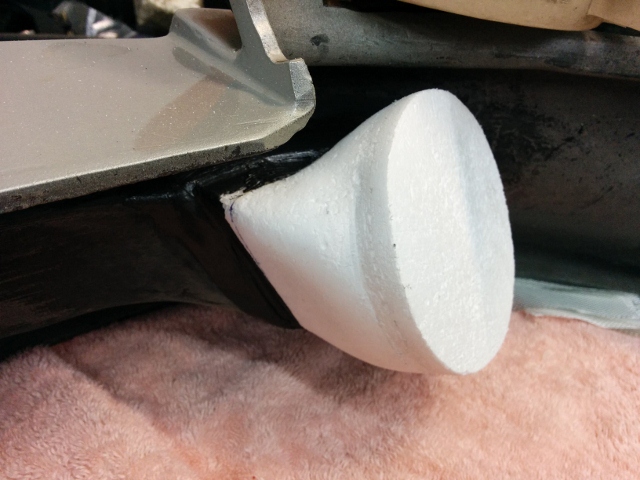
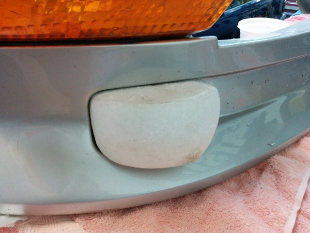
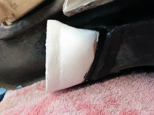
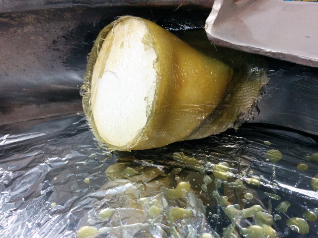
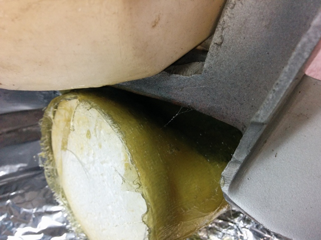
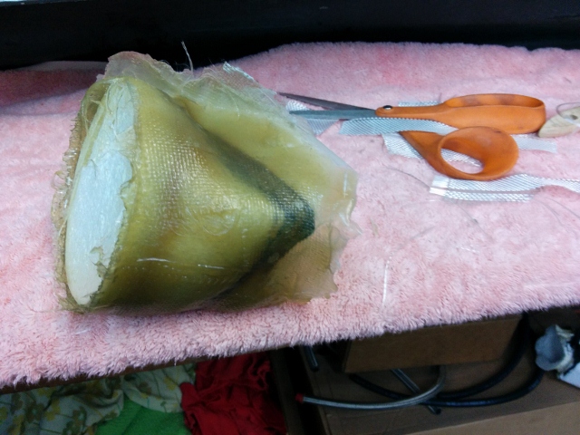
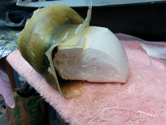
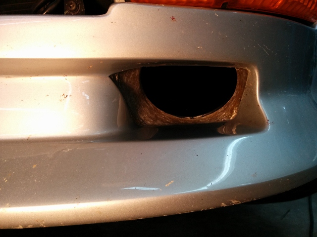
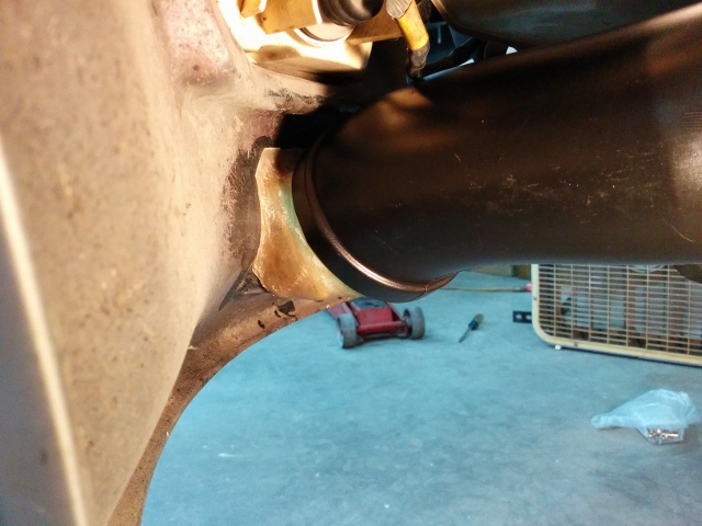
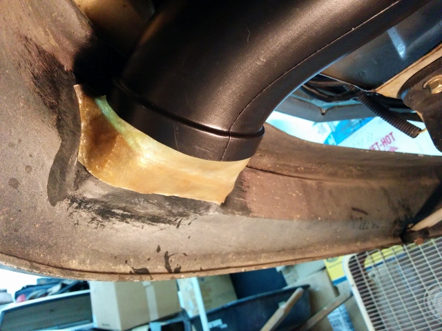
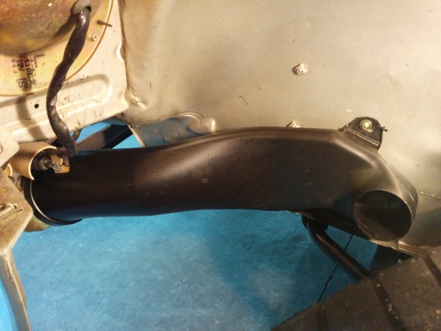
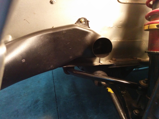
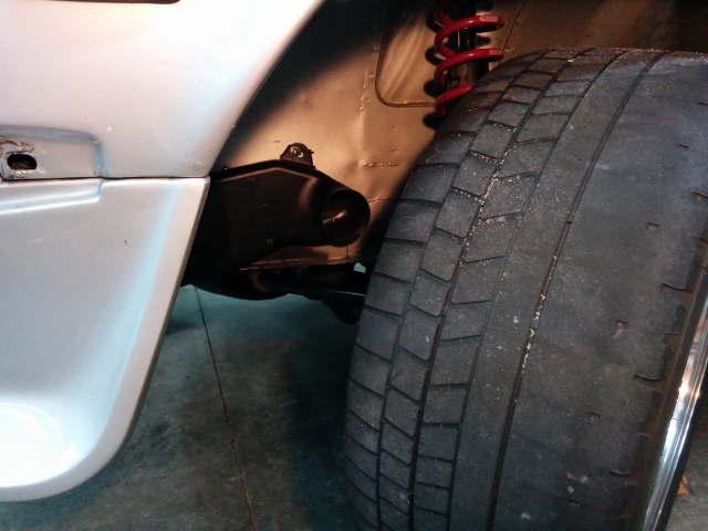
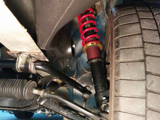
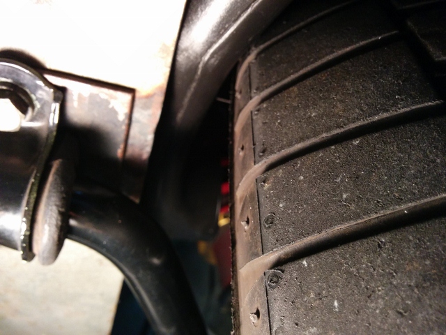
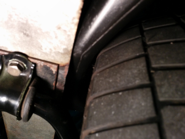
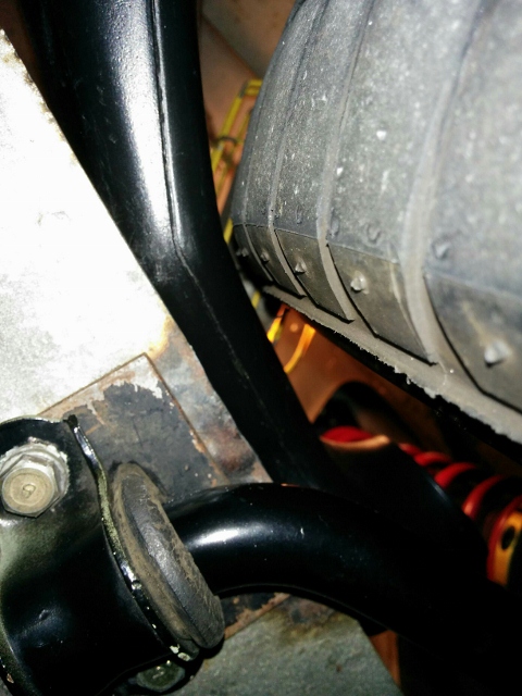
I've been working on installing some new brake ducts. I am running the common Xenon Urethane air dam. I was looking at my C6 Corvette Z06 brake ducts a while back and they looked like they might be good for the Z (240 that is). So I took one side off and mocked it up on the Datsun. It fit pretty well, so I ordered a pair. They are about $30 a piece if I remember correctly. I have had them a while, but finally got serious about putting them on because I am getting the car ready for a track event. To fit them, I made some styrofoam forms... One thing I did not know, as this is my first time making fiberglass parts - styrofoam is made from polystyrene. And, standard fiberglass resin is made of some type of styrene as well. That is not good, as the resin reacts with the foam - it "eats" it. Halfway through putting on two layers of cloth, my form was disintegrating. Luckily, I did them one at a time. And for this second one: I bought a can of spray "polyurethane". 6 coats of that on my second form put a layer of "urethane" between the resin and the styrofoam. The second form did not react with the resin. The black you see inside the fiberglass is some high temp silicone that I had on hand to seal the gap between the foam and the air dam - this kept resin from seeping through to the front side of the air dam. It was easy to remove after the resin cured. A bit of laquer thinner poured into the center of the foam and it melted away leaving the fiberglass part. After some clean up with my little air powered belt sander, it was ready for fitment: Not sure yet if I can go full lock on both sides without rubbing, but it looks like I have a chance:
-
I test drove the car this past weekend and I can report that the 11/16th slave is absolutely working better than the 3/4, and this, with the clutch pedal height set to essentially the factory shop manual (FSM) height, which considerably shortens the amount of travel at the master cylinder vs. my previous setting. The clutch pedal pad is visually even with my brake pedal pad height now. I will order an original 240Z slave to replace the Pathfinder unit because these things are cheap and I want to remove the washer/spacers I had to use with the Pathfinder unit and have the bleed screw and hose in the proper locations. I'm going to do this before I take the car to the track again - this will be the first time for the new engine. The last time I had the car on the track was like 5 or 6 years ago.
-
I finally got around to ordering the pathfinder slave cylinder and got it installed tonight. Here is some info while it is fresh in my mind: I don't recommend the pathfinder slave for a couple of reasons. First, the casting is such that the flat part of the mounting ears that seat against the transmission are not in the same place as the OE 280ZX one. The cylinder part of the casting hits the tranny casing well before the ears contact. You have to install a stack of about 1/4" of washers (or even more) under the mounting ears in order to mount it. I used three thick washers per ear. Next, the bleed screw and the hydraulic fluid supply hole in the slave for the hose are reversed from the OE slave. When mounted, the hose is the highest point and the bleed screw is down low. It still bleeds, but switching positions for these is not desirable. I did some travel measurements, but they are not all in front of me and I'm not going to go ffind them all right now. What I recall: With the OE slave cylinder unbolted and away from the transmission, I put a piece of pipe over the end of the fork to use as a lever arm and manually operated the clutch fork while taking a travel measurement. I measured from the front edge of the slave cylinder boot to the front edge of the fork. I measured pretty much right on 5/8th's of an inch from rest position to "that is all I can get with this piece of pipe" position. I did this about 4 times putting a fair amount of force on the pipe to try to get more travel and couldn't. The pressure plate springs seemed to be bottoming out and not allowing more travel. After installing the 11/16th's Pathfinder slave with the stacks of washers and bleeding it, I took more travel measurements. At rest, the distance from the front edge of the slave boot to the front edge of the fork was 1.140". The hydraulic system was bled and locked down with the clutch pedal bump stop screwed all the way in (so as to be as far from the pedal arm as possible - it was not touching the arm in this position). The clutch pedal rubber pedal pad surface was nearly 2" above the brake pedal pad surface. My brake pedal height is as factory shop manual (FSM) height. I then used my handy dandy "the club" steering wheel lock wedged between the seat and the clutch pedal to hold the pedal tight against the bottom factory rubber stop, which the pedal hits when fulled depressed. I took another measurement. I don't recall this measurement exactly at the moment, but it was something like 1.9" which kind of freaked me out -- I gotta say. Because that is like over an 1/8th inch more travel than I got using the piece of pipe. I wonder if the pressure plate springs were bottomed out and were bending, yielding to the extra travel! I dunno... But, assuming that was too much travel, I went back to the idea of setting the clutch pedal to the same height at the brake pedal - this reduces the amount of travel at the clutch master cylinder. First, I set the clutch pedal at the same height as the brake pedal. I locked the lock nut on the rubber pedal stop. I then hooked up my bleeder hose and released the pressure in the system. This set the piston in the slave back to "full rest" or the "fully retracted" position. i confirmed that the fork was not under load, that the slave was not pushing against it. The fork moved a smidgen when wiggled back and forth by hand. I then used "the club" again and measured travel at the slave as I had done before. I got something just less than 5/8th's - i can't remember exactly. So, I loosened the lock nut on the rubber pedal stop and turned it in two complete turns so that it backed a bit away from clutch pedal arm. That caused an increase in the travel at the clutch master cylinder by a very small amount. I found that setting the clutch pedal just a touch higher than the brake pedal (about an 1/8th of an inch) got me really close to the .625" of travel that I saw when using the pipe. Assuming my 5/8th's total measurement is close to accurate for actual full travel on my pressure plate... combined with my current pedal height, and my current clutch master cylinder rod setting, this set-up "should be" providing me with full pressure plate spring disengagement. It's too late tonight for a test drive. I'll check it out this weekend. Regardless, even if this work's it's not a good enough solution for me. I don't want this particular slave cylinder. I'd like to find one that fits better; without washer/spacers and with the bleed screw and the hose in the proper locations. Second, this has me thinking about potential differences in the 280ZX and the 240Z (mine is a series I) clutch pedal assemblies. My clutch MC, and the slave that were in the car are correct, 280ZX units - 5/8th's and 3/4" respectively. Setting my clutch pedal at the 240Z FSM height off the floor... doesn't work at all. The clutch is non-functional - I can't select any gears with the engine running. Perhaps my aftermarket performance pressure plate (ClutchMasters) is part of the problem. But, I am thinking the problem is actually a difference in clutch pedal travel from one car to the other. I think the stock 280ZX clutch pedal travel is substantially greater than the stock 240Z clutch pedal travel. This seems much more likely to be the issue to me. Maybe that is the "problem" everyone who has a 240Z has been fighting when they swap out to the 280ZX tranny, and can't get the clutch to adjust correctly. I have a 280ZX FSM. So, I'll take a look at that when I have some time.
-
Mikuni 44 phh - pump stroke really supposed to be 7.5 mm???
inline6 replied to inline6's topic in Fuel Delivery
If you look at where the measurement is taken, it measures the full stroke of the lever. That's not going to change without the cooling block or with. The pump lever actuating rods just have to be longer on the carbs that have the cooling bodies. -
Hi, I'd like to buy six 39 mm outer venturis in very good used condition. Will go with 40's if I can't find 39's. Thanks! Garrett
-
I started to order it from RockAuto, but decided shipping and handling or whatever was a bit much for the one part. Am going to find a couple of other items I need and get it coming. Also had the thought to do some measuring. I mean, I can measure how much M/C rod moves for each inch of pedal movement, and the same for the slave. I should be able to take the FSM clutch pedal stroke (8" from floor to clutch pedal stop) and knowing the diameters of the stock M/C and slave, calculate volume displacement for each. Then, I might be able to figure out what size m/c and slave would be required to work with that same stroke to get full disengagement.
-
To be clear, I don't like the situation. I'm just describing it. I'd like to come up with a solution so there is enough fluid being passed to give the slave the travel that needs to occur for full clutch disc disengagement... with stock clutch pedal stroke. There is always this option - lol
-
The spring diaphragm mechanism on the pressure plate pushes everything (the t/o bearing, sleeve, fork, and clutch slave piston) back. It all settles... with the c/s piston in a position which is pretty well bottomed out in the slave. I confirmed this by removing the two bolts that mount the slave and trying to compress the piston more. It doesn't go very much further at all... maybe a 1/16th of an inch. Right now, on my car, the piston on the slave is "out" enough that of its total 21.8 mm of travel (again, with the way everything is set in my car right now), 6.6 mm of it is gone. So the remaining 15.2 is available. If I were to crack open the bleeder on the slave, then the piston in the slave would again retract fully. And given everything else in my clutch system is not changed, once I tighten the bleed screw again, I'd have a not functioning clutch because I'd only have 15.2 mm of travel available. In order to get more, I'd have to back of the little bump stop that holds the pedal at ~ the same height as the brake pedal again. That would retract the piston in the clutch m/c so that once pushed forward again, I could again pick up the 6.6 mm that was lost when the bleeder screw at the slave got opened. I could again set the clutch pedal height using the little rubber bumper pad, but I'd be right back where I am as the car sits - 6.6 mm of a total of 21.8 mm of stroke having occurred at the slave already. I don't think he is using mechanical means. If you push in the clutch pedal somewhat, so that the slave is engaged and moves the clutch fork, and you then lock the position (with the little rubber pad that contacts the pedal), you've pre-loaded the clutch... with a hydraulic system.
-
Did some measuring today. I backed the rubber bump stop away from the clutch arm completely. I set the clutch m/c rod so that the clutch engagement off the floor felt right - not too high off the floor, not to low. My clutch pedal was roughly 1.5 to 2 inches higher than the brake pedal which is at FSM height. I then set the clutch pedal so it was hard against the clutch pedal stop on the floor. Then I measured the clutch fork distance from the slave. After writing that number down, I released the clutch pedal completely and measured the the clutch fork distance from the slave again. I calculate that I have 21.8 mm of total throw at the slave right now, but... I then set the rubber bump stop against the clutch arm to bring the clutch pedal to approximately the same height as the brake pedal. And I took another measurement at the slave. With the clutch pedal height reduced, I now have 15.2 mm of travel at the slave. That means the slave has been activated by 6.6 mm... with the clutch pedal now in the new static position. I drove the car, and shifts are not bad. I also don't notice any clutch slipping. But with 6.6 mm of travel already occurring (this is net of any slop in the clutch pedal linkage by the way) the t/o bearing is clearly "running" at all times, and the pressure plate spring fingers are somewhat depressed. This is not right enough for me...
-
Nice. Plus one for buying a $9 dollar 11/16ths slave and giving it a shot. Regarding the clevis, I read where one person modified theirs just by drilling the threaded hole out of the clevis they had and welding a nut with thread that matches the rod to it. If you have a welder, that may expedite your project. A lock nut is still needed, of course. 7/8" is "a lot" bigger than 5/8" when it comes to these master cylinders, isn't it? My car is already beastly to drive in so many ways after various mods... adding another by switching to a heavy clutch pedal doesn't appeal to me.
-
But, doesn't pre-loading of the T/O mean the pressure plate spring fingers are loaded also? And so the PP isn't clamping with full available force? I can see how that would still work, but one really doesn't know how much slippage is occurring, right? A suitable compromise... sure, but I would prefer to have properly engineered/functioning parts. I'm curious how much of your "solve" of high rpm shifts is your mods. vs. more travel, by the way. If I get enough travel, I may find out.