cgsheen
-
Posts
672 -
Joined
-
Last visited
-
Days Won
8
Content Type
Profiles
Forums
Blogs
Events
Gallery
Downloads
Store
Everything posted by cgsheen
-
The pedals and peddle box are the same for all 1974, 1975, and 1976 Z cars. IDK what changed with the '77-'78 280Z's, but '74-'76 are interchangable.
-
Be sure to get this document from the DIYAutotune site: https://www.diyautotune.com/support/tech/hardware/nissan-trigger-disc/
-
L28et swap not starting/staying on
cgsheen replied to superduner's topic in S30 Series - 240z, 260z, 280z
Oh... You have a REAL '81 CAS? Doesn't matter - input to the ECU is the same as with the '82-'83 optical CAS. You can use an Auto ECU with a manual transmission and vice-versa. The difference between the ECU's has little to do with the EFI and more to do with the transmission lock-out (safety feature on the 280ZX). And yes, I've used an '82-'83 ECU on an '81 harness for testing purposes and it works. If you leave the '82-'83 ECU on the '81 harness, you need to jumper out the dropping resistors. If you're getting power to each injector, the dropping resistors are good. There is one resistor for each injector. -
Yes. Refer to page 76 of the MS2/V3.0 Hardware Manual. "Connect a 330R 1/4W Resistor between IGBTin and the top of R26." Be sure to follow all the steps in the section 5.3.1.1 on page 76. For the "pull up" resistor (1K) needed when using the Nissan CAS, use the proto area on the version 3.0 board. It's very easy to fit IC's and discrete components in the holes. Fit your resistor in there and then use wires from S12 to one side of the resistor (that's your 12 volt source) and from the other side to TachSelect like the "Using DIYAutoTune.com's Nissan Optical Trigger Discs" .PDF says. Be sure to follow the other instructions in that document - there are other hardware mods to be made on an MS2/V3.0 board. Note that there are GROUND and +5V "holes" (connections) in the proto area - stay away from those for this connection. I find it easy to insert the resistor and bend the leads over towards an adjoining hole. Cut the lead so it just barely goes to the adjoining hole. insert the stripped wire end in the adjoining hole (insulated wire is on the same side as the resistor, bare wire goes through the hole to meet up with the resistor lead on the opposite side of the board...). Lap the bare wire over the resistor lead and solder them together.
-
L28et swap not starting/staying on
cgsheen replied to superduner's topic in S30 Series - 240z, 260z, 280z
The ECU light is normal. It lights at IGN ON and goes off as soon as the ECU gets a CAS signal. That's normally during cranking or engine start. The buzzing, I've never seen before... Is that buzz really coming from the injectors? Check the injector wiring again. (stock)They should have power through a fusable link and the ground is controlled by the ECU. If there are no problems on the +12v side AND the wiring from the ECU is good with no continuity problems (shorts) than you likely have a problem with the ECU. The 1981 ECU needs dropping resistors in the harness. You've already been through the harness and connectors and cleaned the hell out of everything electrical connector related, right? -
CARBOTECH AX6 PADS FOR TOYOTA & 240SX CALIPERS
cgsheen replied to Miles's topic in Brakes, Wheels, Suspension and Chassis
Good to know they have pads for the Toyota 4-piston. Phil Robles swears by Carbotech on his race Civic. -
You should probably describe your setup - engine and spark configuration. Although to me at least, it sounds like you're using a single coil and already have an igniter (transistor ignition module, electronic ignition, blah, blah...). If that is the case, then the second bullet would be for you. Although for my MS2 v3.0 board builds I've been using the MS2/V3.0 Hardware Manual that Chickenman linked above and it doesn't have the same "step 22" that you're showing above.
-
If your air regulator is bad, the vane never closes and you'll always get bypass air into the manifold. A couple of minutes after start the vane would normally be closed and there would be no bypass air (if it was working properly). IDK if that will help your emissions but I'd block off one of the hoses if I wasn't inclined to make it work the way it should...
-
Safe to chemical-strip Fiberglass headlight buckets?
cgsheen replied to ByStickel's topic in Body Kits & Paint
They make a version of Aircraft Stripper specifically for fiberglass. +1 for neutralizing any paint stripper with water when it's done it's job. -
How many threads on coilover to be safe?
cgsheen replied to AlbatrossCafe's topic in Brakes, Wheels, Suspension and Chassis
The top two locking nuts make up the lower spring perch. They generally they shouldn't be adjusted other to assure that the spring is snug between the upper and lower perch. You normally don't want to "pre-load" the spring. (raising the lower perch otherwise will compress the spring = pre-load - it does not lengthen the strut assembly) The exception to this is if you had your car corner balanced - then the Tech would adjust the pre-load as necessary. The short answer to your original questions: 1. No, 5 threads is are not enough. Rule of Thumb is that the strut cartridge should be screwed in approximately the diameter of the threaded adapter - so, about 2" as a minimum. 2. No, Alignment and track width will not affect ride height in a significant way. 3. Ummmm... I think the best way would be to go back to your welder/fabricator and have him add back in at least a couple of inches on the stock strut tubes. (nice welds BTW...) About the minumum safe distance for the strut cartridge in the adapter: Give the super nice guys at Stance USA tech support a call. Their struts are all steel, they may not need a 2" insertion, but those guys will give you the facts. 847-290-1568 After you talk to Stance USA, screw the cartridges into the adapters the amount they say. Figure out how much you need to lift the rears and have your welder add at least that much back into the rear stock tubes (keep in mind that you still have some drop in those adapters). Hopefully you can live with the fronts - that will be more difficult to change at this point. A few things (you're already past most of this, but it's mostly for others installing their own): This is why I was trying to stress "doing the math" first. Especially since you wanted to stay near stock height. Not one other person that I know of has installed our kit to maintain stock ride height. So, asking them how they did theirs would not help you. To figure the math properly, you would need to measure the loaded length (springs compressed normally) of your stock struts. From the top of the isolator down to the hub. Wheels on the ground, everything in the way... Compare the stock strut length with the assembled length of your Stance USA strut cartridge (strut cartridge threaded into threaded adapter 2", lower spring perch unchanged (or adjusted so the spring is just snug), pillow ball in place, aluminum lower camber plate attached to pillow ball if using our camber plates) Measure the length of this assembly from the bottom of the adapter to the top of the camber plate. - Your new springs will compress slightly but not nearly as much as the stock springs did - probably an inch or less. - Also keep in mind that with 2" threaded into a 6" adapter, you still have another 2"-3" to lower. - leaving an inch of the stock strut tube in the adapter is really not necessary. 1/4" is sufficient when welding to the hub. 1/2" is more than enough when welding up on the tube. With those measurements you can compute the proper position of the threaded adapters. Example: (totally pulling these numbers out of the air) The stock length of the rear strut is 25" from the hub to the top of the isolator with the car sitting normally on the ground. The assembled length of the Stance USA / Sakura Garage coilover (as described above) is 21". Let's suppose that the Stance spring will compress 1" with the weight of the car. 21" - 1" = 20" (adjusted length) 25" (stock strut length) - 20" (adjusted Stance length) = 5" height difference. The threaded adapter would need to be welded up 5" on the tube for stock ride height. If you plan on keeping a 1 1/2" lower stance on the car, the adapter would need to be approx 3 1/2" up the tube. (5"-1 1/2") Keep in mind the adjustment (lowering) you still have in the threaded adapter... -
Sakura Garage / Stance Coilover Install
cgsheen replied to JavelinZ's topic in Brakes, Wheels, Suspension and Chassis
I need to add a note here: JavelinZ used our 9" long threaded adapters for the rear of his 280Z. Albatross has 6" long threaded adapters all around. (We were getting inconsistent results from our machinist, so we discontinued having our own threaded adapters made - we now only use the 6" long adapters from Stance USA) With 9" rear tubes, Jav welded them straight to the rear hub. Using 6" tubes, he would have to come up 3 inches on the stock 280Z rear strut tube to get the same result. -
Sakura Garage / Stance Coilover Install
cgsheen replied to JavelinZ's topic in Brakes, Wheels, Suspension and Chassis
Not really necessary if you're welding to the hub. The strut tube mostly serves as a centering device in that scenario. -
Is this the correct door for my Early 71 240Z
cgsheen replied to 5 Star Rising's topic in S30 Series - 240z, 260z, 280z
+1 The only thing I would add is: the gap at the front of the door and fender may also require repositioning the fender itself. Get the gap at the back of the door set correctly to the rear quarter and get it aligned to the body line and latching correctly. Then, move the fender to correct the gap at the front of the door if necessary. -
Sorry I haven't been back to this. Nissan describes the optical module as creating a sine wave that is cleaned up by the electronics into a square wave. And ya, it's definitely a 5 volt to 0 volt wave. I have MS3 (base) running my L28ET now using the diyautotune L28ET optical wheel for crank and cam input. (I did COP using Nissan coilpacks and ignitor. And installed the electronics for logic level spark outputs for full sequential.) The crank and cam inputs are Wired up as per their instructions - I put the pull-up on the MS board. I've been really impressed at how stable the signal is - never had a sync error...
-
The CAS produces a 0v to 5v square wave as the slits pass. If you were to pull the distributor and turn it by hand (with the CAS powered (ignition on)) you should measure 5v when the slit passes (open hole for the light to pass through) and 0v otherwise (when the disc is blocking the light). And that should happen on both White and Green wires. But Tuner Studio should show your crank and cam signals if it's getting them. Easy to test the CAS by hand though... If you're not getting a 5v spike, the module is bad. Any Nissan or Infiniti with a VG30E should have the optical module you need. But, I've gotten most of mine from M30's or Maxima's. Might not hurt to check if the 4 cylinder cars of the era used that optical module.
-
Wait... If you're using an ignitor (transistor ignition, electronic ignition module), are you using a logic level spark output to the ignitor? I'm a bit of a noob with MS, but I see the BIP installed and isn't it a high-current spark output to drive the coil directly? (without the need for a transistor ignition module) Sorry if I'm off base, but your comment about using a Z31 coil and prw-2 stuck out to me...
-
Stance coilover kit, front woes :(
cgsheen replied to sileightygx's topic in Brakes, Wheels, Suspension and Chassis
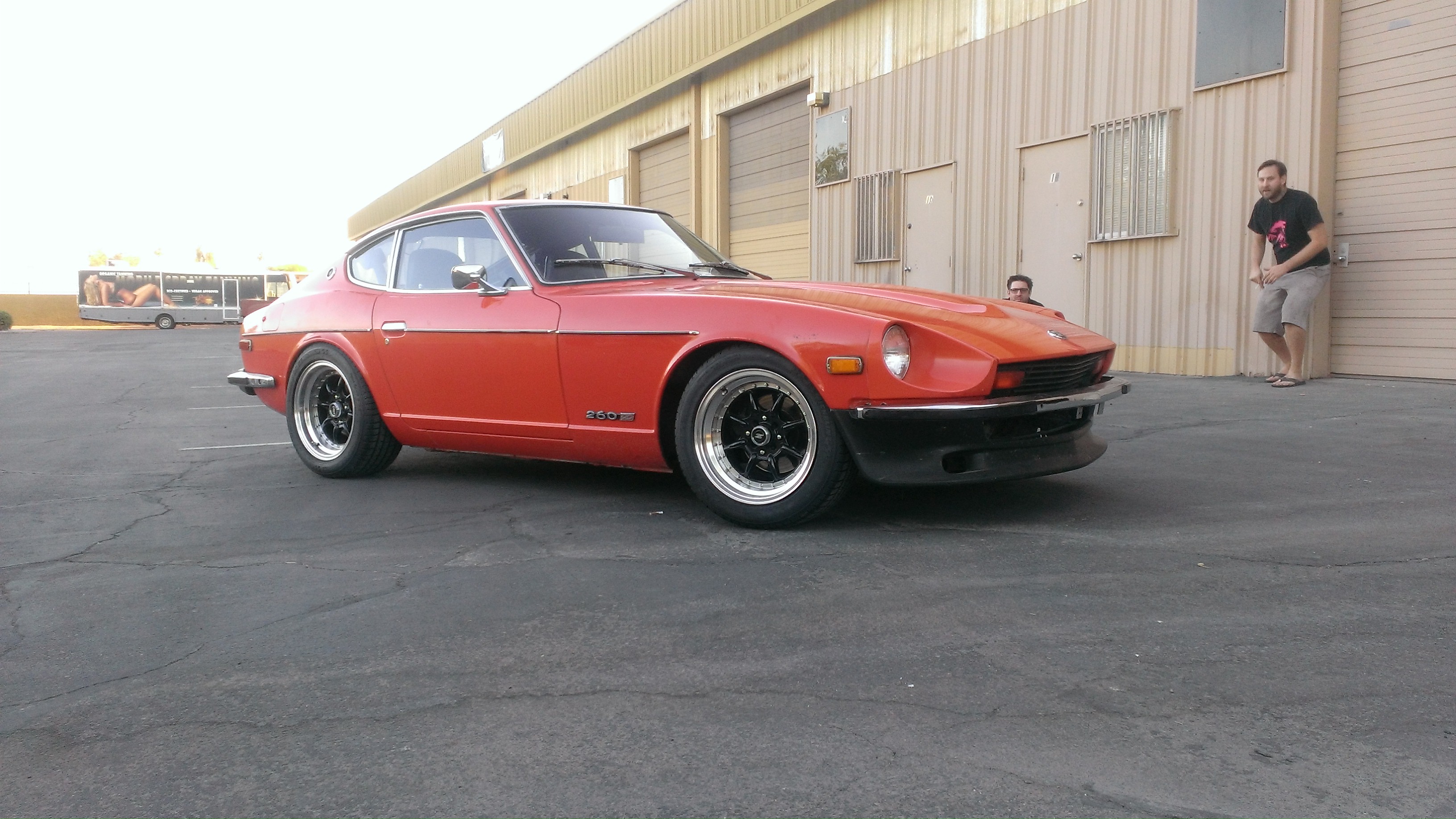
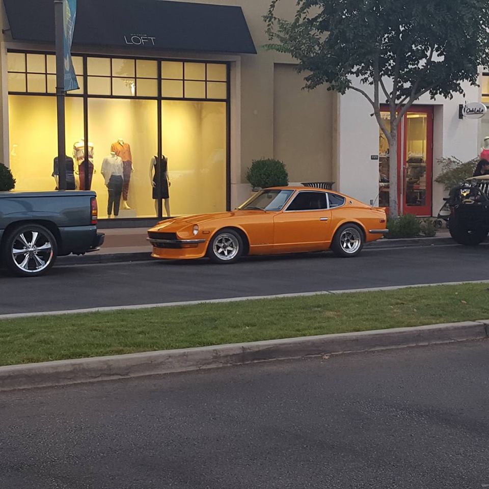
Luke - everything looks pretty much correct in your pics. The springs should come with no pre-load. All the struts should be the same length. And the strut I have here is the same length (well, it's closer to 10 1/2 " "top of threaded portion to bottom"). 7" spring, 1/2" spacer under the pillow ball, and the pillow ball bolted to the aluminum camber plate which is bolted right up to the bottom of the strut tower - right? What's the measurement between the ground and your frame rails under the floor / seat area? Your first pic doesn't look quite right (front tire fitment in the fender) and our experience has been as stated above - plenty of travel. Most of the installs we've done here we can get the frame pretty close to the ground if we wanted to. Our installs usually end up being close to stock height at the upper range of adjustment with about 3" of downward adjustment. That's figuring the strut being screwed in a minimum of 2" at the upper range. We also cut the stock strut tube down to a nub - 1/4" or less - but that doesn't really impact our installs. We don't go down into that last inch anyway as a general rule. (Adapter tube is 6", minus 2" for minimum thread, 3" adjustment range, 1" at the bottom unused (the adjustment knob is there)) Your picture that shows the front lower control arm is skewed so I can't really see the geometry. Can you take a "flat and level" pic of it from the front? Do you have a roll center adjuster (bump stop spacer) installed? I'd also like to see a frame-to-ground pic. First pic is our shop install on Patrick's 260Z front. Second pic is Patrick's 260Z outside after the install (he's lowered it a bit more than we did since that pic) Third pic is an early - SoCal car with our coilover set - Jorge did an awesome job, right?
-
Sorry, I haven't checked this in a while! I've PM'd you Albatross. Also, our website is actually broken. It was built with WordPress years ago and we're not smart enough to keep it updated properly. Their last update made the website unresponsive. We were a little slow finding that out. Right now we're looking at the option of either repairing the old site or building a new one. In the meantime, email us at sales@sakuragarage.com.
-
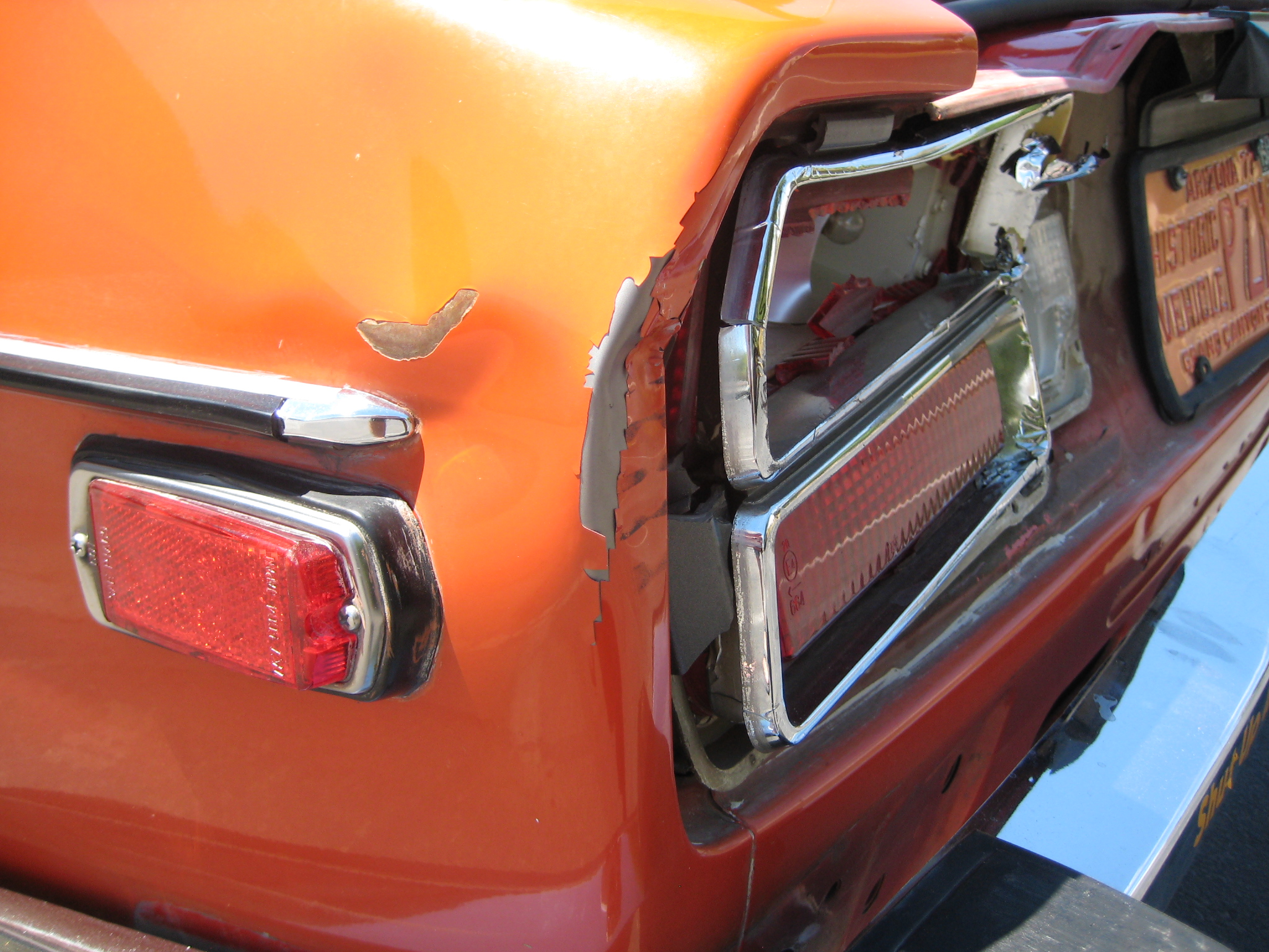
Well, I do straighten those occasionally... Gotta remove the fuel tank though. Then, it's a lot of spoon, hammer, and dolly work from both sides.
-
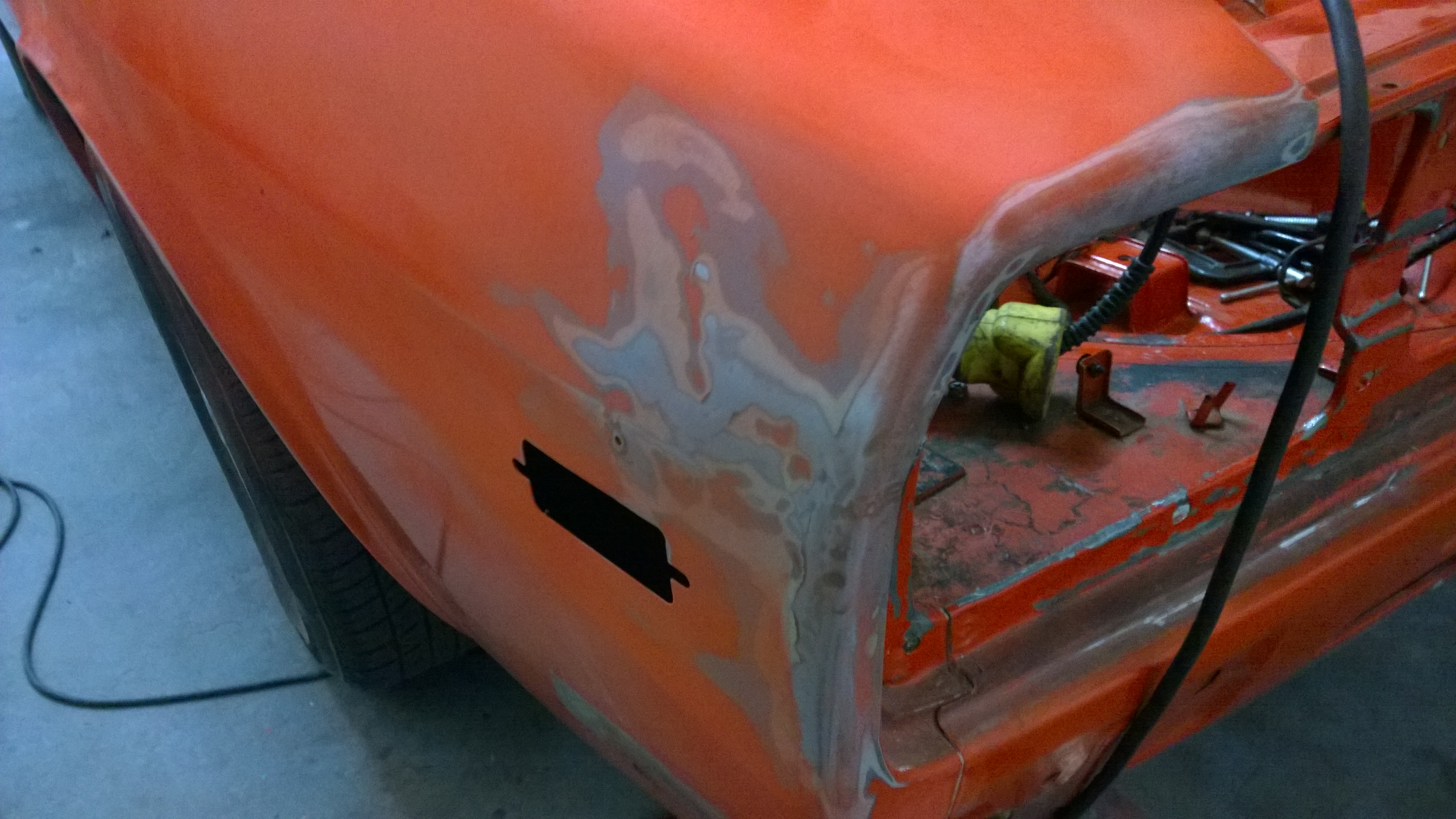
+1 Patricks 260Z was hit by a Silverado. There's a bit of room behind the rear quarter. I was able to hammer it out and get it close enough all it took was a skim of glaze to get this corner back.
-
Wheel spacer doesn't fit 280z front ;(
cgsheen replied to AlbatrossCafe's topic in Brakes, Wheels, Suspension and Chassis
That's weak... Die grinder?? This isn't something new - early Z's have a large front hub. You can fit anything on the rears but the fronts can be a problem for modern spacers and wheels. Super disappointed that Zcardepot would screw you over like that... Sakura Garage - Tempe, AZ -
Oil Filter Pressure Relief Valve Plugged?
cgsheen replied to Cannonball89's topic in Nissan L6 Forum
Ding, ding, ding. On the L28ET the bypass is in the sandwich plate for the oil cooler and the block is plugged. -
The L28ET ECCS harness (engine harness) is pretty much self-contained. You won't need any of it for an L24 setup. You won't be using the turbo coil and ignitor - there may be some wiring there to be removed also. There will be some relays that they would have to add and wiring connections into the 240Z harness(es) that you will no longer need. Anything that ties to the ECCS harness can be disconnected and removed. Getting the stock harnesses back to normal will entirely depend on how they did the turbo swap and if they eliminated any of the stock wiring when they did it. If you're not familiar with stock 240Z wiring, that may be difficult to know what - if anything - they changed or removed. Good thing is: 240Z engine wiring is pretty simple. Alternator may be something to look at. If they switched over to the internally regulated alternator that would be stock on the L28ET, you may want to just stick with that rather than going back to a stock 240Z alternator... BTW, I'll take your turbo engine ...
-
Refer to the 1972 240Z Factory Service Manual. Emissions Control section - page 2. l24emissions.xps
-
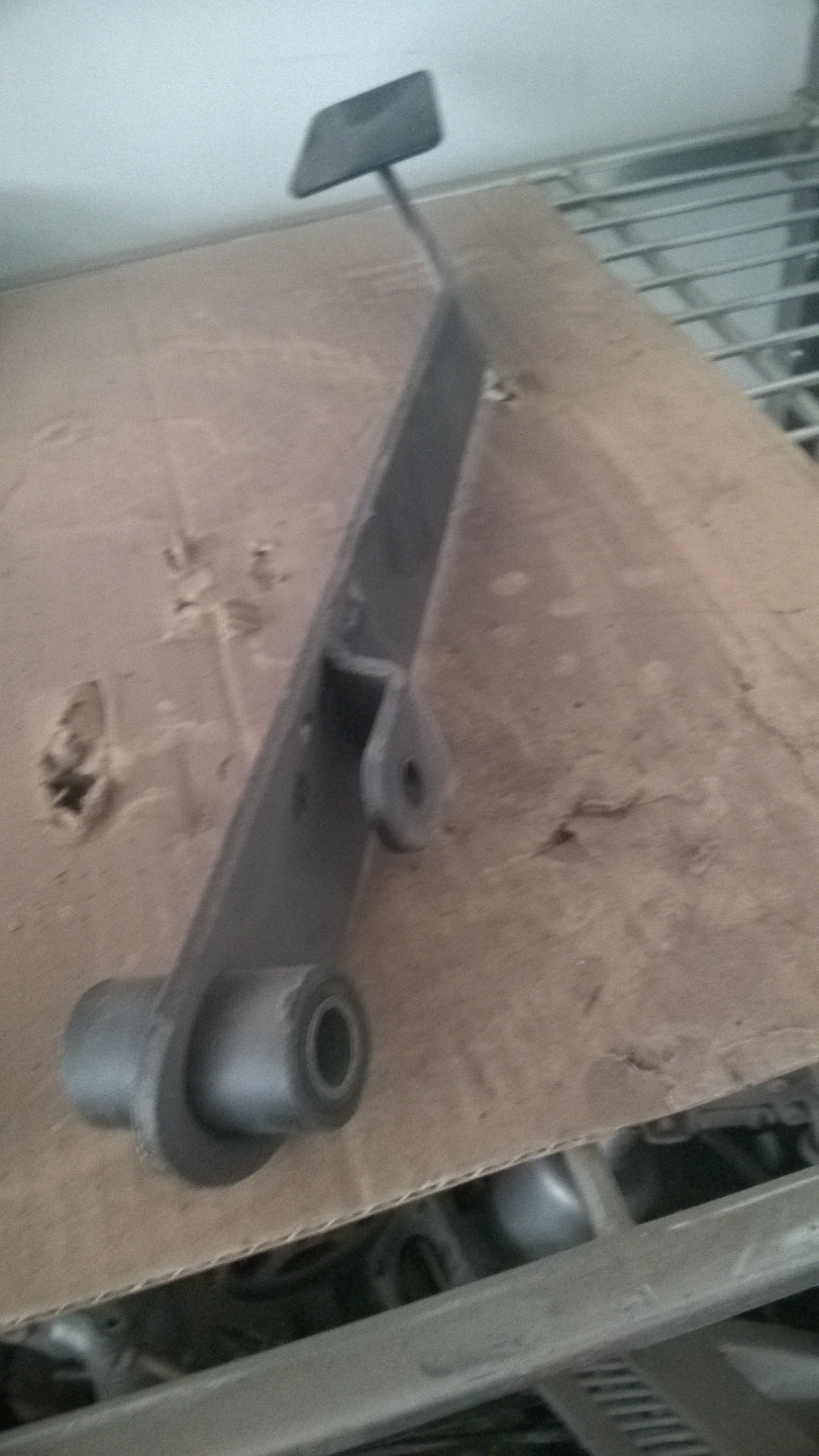
Clutch master cylinder pedal connection
cgsheen replied to mrk3cobra's topic in S30 Series - 240z, 260z, 280z
This picture is of a "late" clutch pedal - used in a 260Z and 280Z. The 240Z clutch pedal was different - made of thinner steel and curved along it's length to add strength. At some point (1973ish...) the brake booster was changed and a larger booster was used. The clutch master was moved farther away from the brake master due to the larger diameter of the new booster. The pedal box and clutch pedal changed also. Looks like you need an actual 240Z clutch pedal.