BoonZ
-
Posts
18 -
Joined
-
Last visited
Content Type
Profiles
Forums
Blogs
Events
Gallery
Downloads
Store
Everything posted by BoonZ
-
Steel Datsun used for transverse link mounts?
BoonZ replied to 280Z-LS3's topic in Fabrication / Welding
I did a PMI and hardness test on a bracket from a 1972. The Rockwell test result is 34-40 HRC, a chalange for some hacksaw blades. The PMI test looks like recycled material. Zn 0.023, Cu .11, Fe 97.623, Mn 0.83, Cr 0.043, Ti 0.09 %, All other elements are below level of detection. The PMI gun (Niton XL 2 Gold XRF) will not pick up Carbon. -
Strut mount with height adjustment.
BoonZ replied to BoonZ's topic in Brakes, Wheels, Suspension and Chassis
I ordered jam nuts. But I am not sure if I will go with them or make a tall skinny nut that comes out of the hole. I like touring so the car will see different loads. -
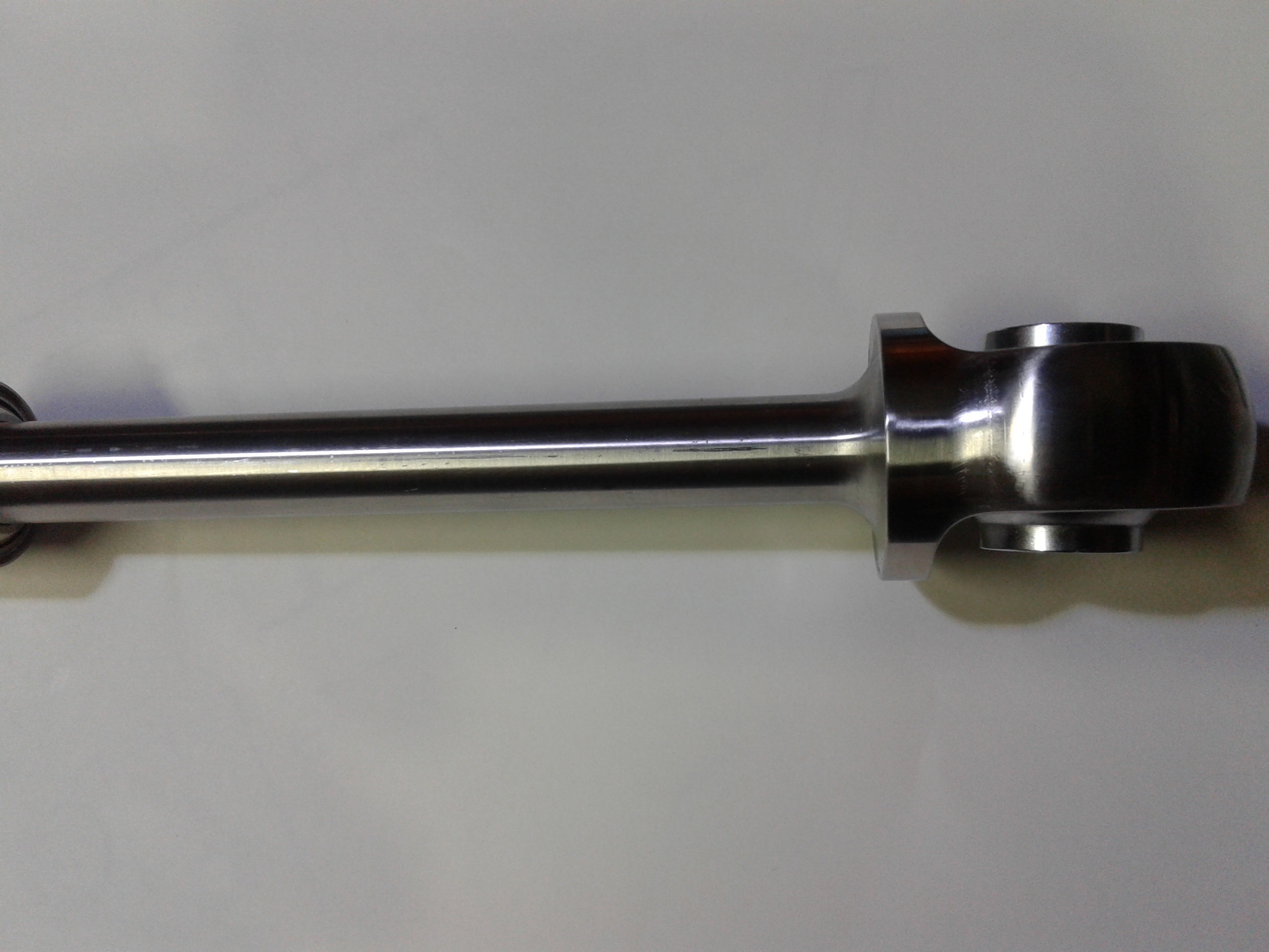
Here is a 240 rubber strut mount modified for height adjustment. The mount was bored to 1.5 inch a steped coller was pressed in. The ID is threaded for a Jack screw. The screw is 1-14TPI bored .625 ID for1.125 inch to fit over the strut. Then drill and tap for the strut threads. The top was countered bored .625 to allow access to the strut adjustment and a hex was broached in it for turning. The spring cap is pressed on the end.

-
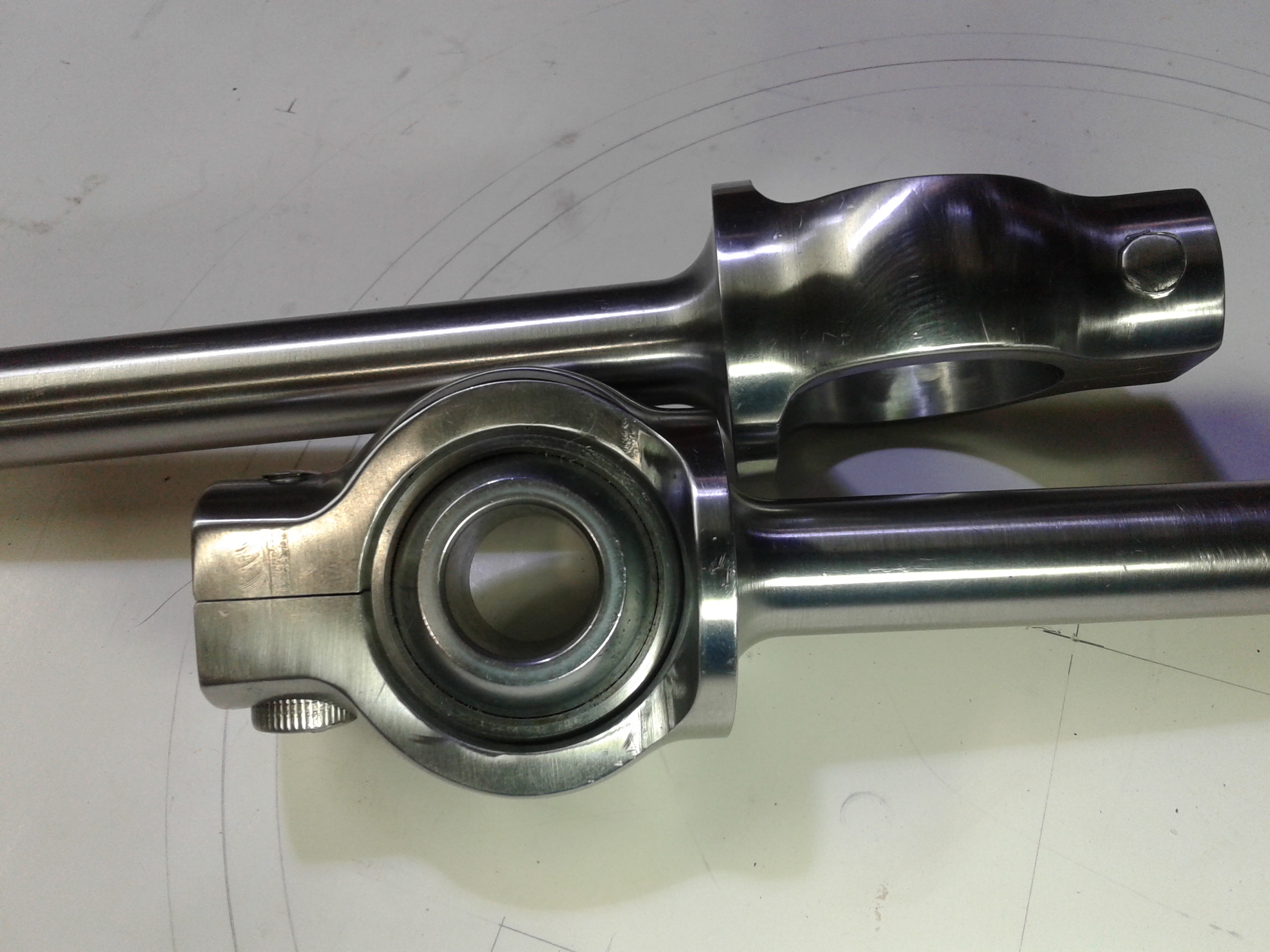
Update, I found that the piviot center of the mono ball in relation to the housing is not controlled. So I changed from a snap ring to a clamp. This gives the freedom to center the mono ball to the pin center. This will also allow the adjustment of the pin pivot axis in relation to the strut. I do not know the angle of the strut to the pin pivoit axis in the side view. I suspect it is 90 degrees. The only struts I have off a car are from a wrecked 240 and looking at the way the rubber bushings are distorted any measurement from them will be questioned as to its value. The car was hit on the rear wheel. If anyone has the angle, can you please share it.
-
I am not looking to sell them. I posted to share thoughts on a different way to achieve a goal. I am still working on the A-frames to go with them.
-
Del-A-Lum LCA bushings
BoonZ replied to Chickenman's topic in Brakes, Wheels, Suspension and Chassis
I had a 240 with eccentric LCA bushings. They were pulled from service in poor shape. The aluminum had deep groves, Bushings tapered. (Maybe from the arc generated by the TC arm). They were made to run without lube. The aluminum is to soft for good soft for good wear resistance. If you can keep the dust out and lube it,service life may be OK for weekend use. I have Moly filed Delrin on the inside of the rear a-frames. They have about 30K on them. The heat from the exhaust warmed one next to it and it would stick. Had to increase clearance from .002 " too .010". Next time I will use PEEK or Torlon with a mono ball in the front. -
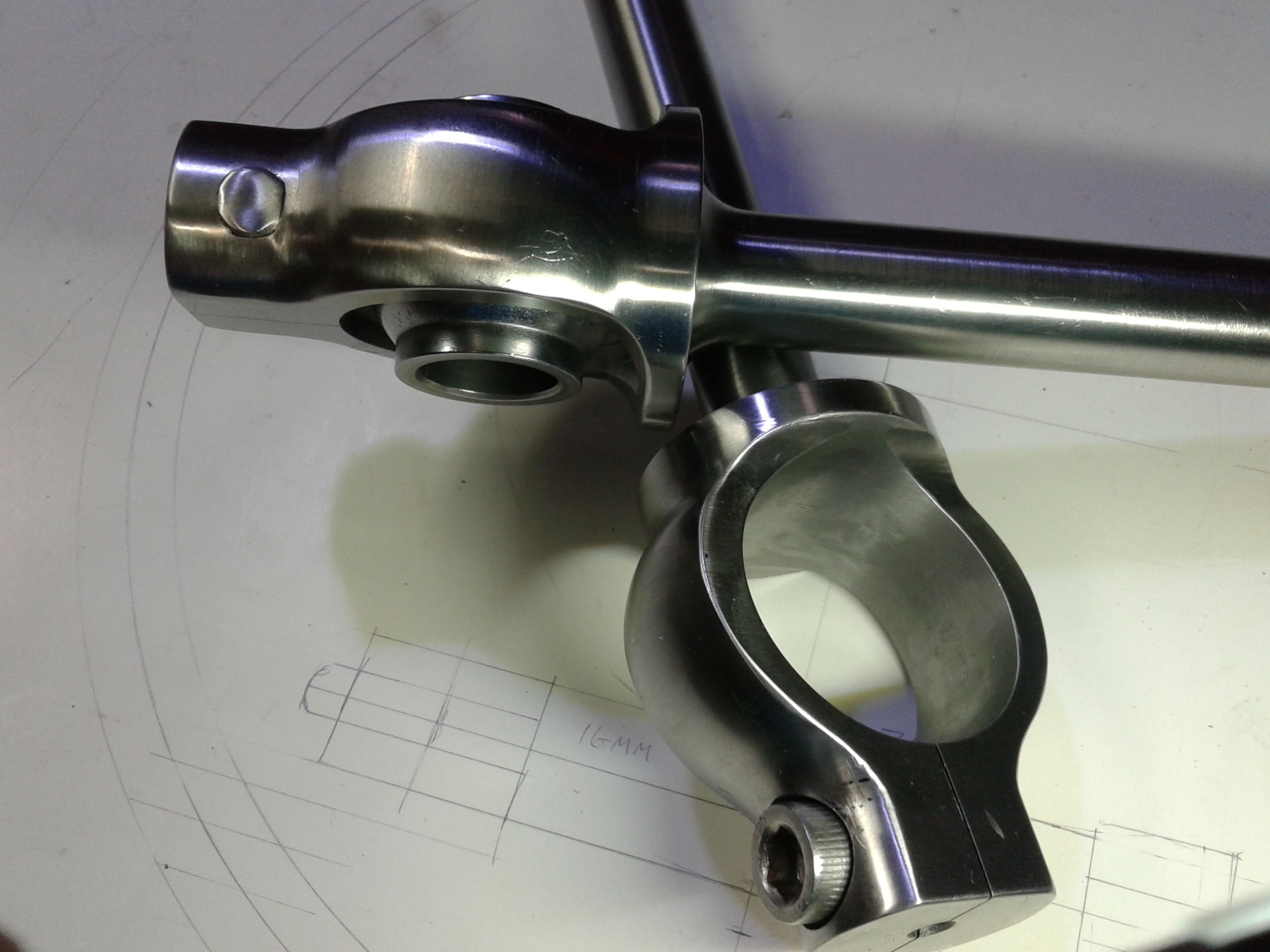
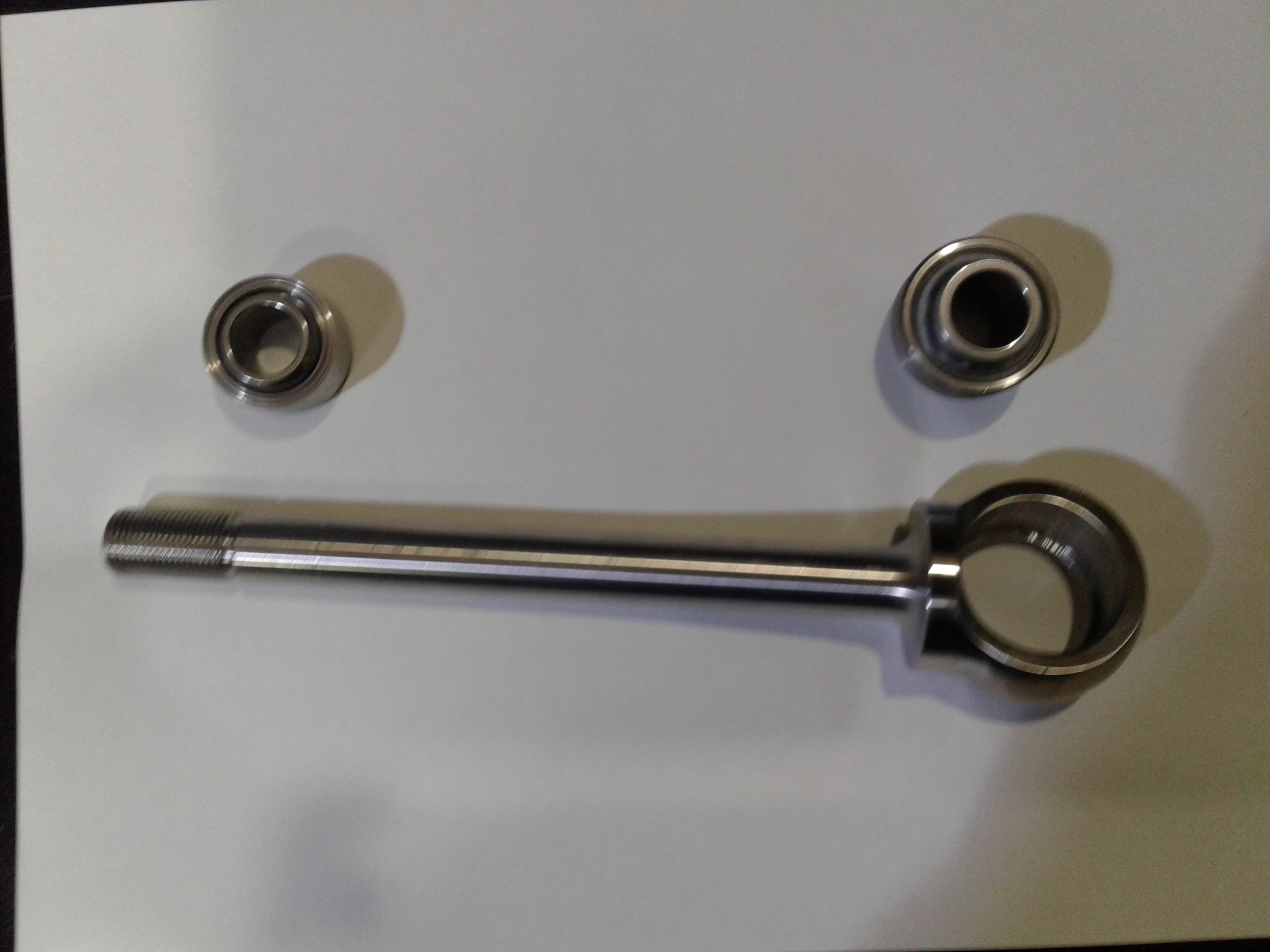
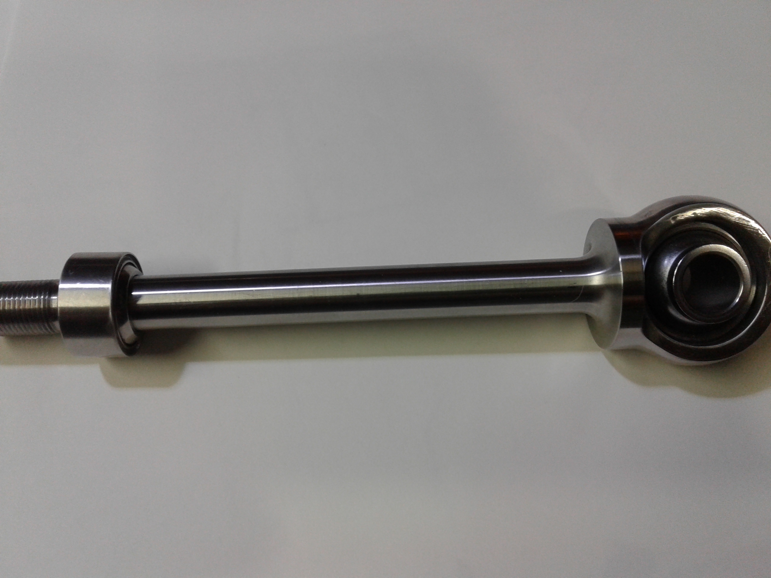
This pin places the front monoball in position for long life and double shear mount. Front ball needs to be a high missalinment type. I used a 5/8 size. The material is 17-4PH 1150 to avoid corrosion.
-
Why are the post I made locked?
-
Front Suspension Kinematics
BoonZ replied to 74_5.0L_Z's topic in Brakes, Wheels, Suspension and Chassis
If some one in Houston,TX. has a cross member to lone out for a week end I will measure it. -
I think most machine shops do not want to deal with a job, with out a detailed drawing. The machinist hand book gives specifications for types of fits. For a rotor ID to fit a hub OD of 2.500" It may be called out Machine ID to 2.501" -.000 +.001" Concentric to OD within .005" If the OD is rough a clean up cut may be needed. Bolt circle call out will be Four .xxx" + -.005" holes on 4.500" circle 90 degree spacing Concentric to ID. This job can be done on a Mill/Jig bore with a boring head or a CNC turning center with live tooling as well as a Lathe and Mill.
-
LLave, It is a Ford DEW98 platform, 2000-06 Lincoln LS,Thunderbird and Jaguar S-Type. It is the TC rod on the back.The out side end ties to the upright. There is what looks to be the same rod on the Ford full size SUV. Next time I am at the junk yard I will look and see if it is the same.
-
Compression rod Ball end Mod. using a mono ball from a Ford IRS. Turn down the TC Rod to 14MM (.551") cut to about 7", thread 14 x 1.5 MM for 2.75" The threading die was purchased from a machine shop supply for $11 the Mono balls from a self serve junk yard for $7 each. This is a simple bolt in BUT the pivot of the mono ball is about one inch forward of the factory. It has a smaller OD than the factory. I am a long way from a finished project, so testing will have to wait. If some one has run with a shortened TC Rod please let us know how it worked.
-
Holley has a accelerator pump diaphragm on the bottom of the float bowl. I find these get hard if not used. When you start using them after a long time out of service they crack and leak the fuel in the bowl down on your exaust.
-
Modifyed Miata power steering rack for 240Z
BoonZ replied to BoonZ's topic in Brakes, Wheels, Suspension and Chassis
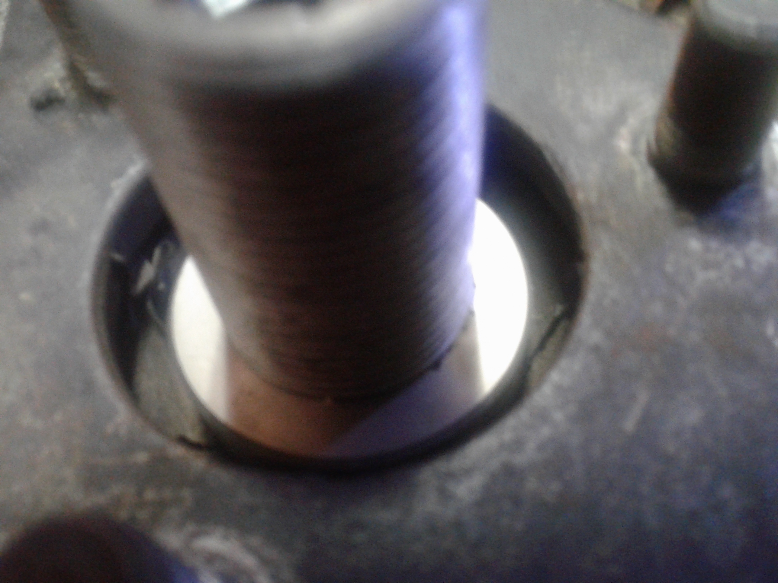
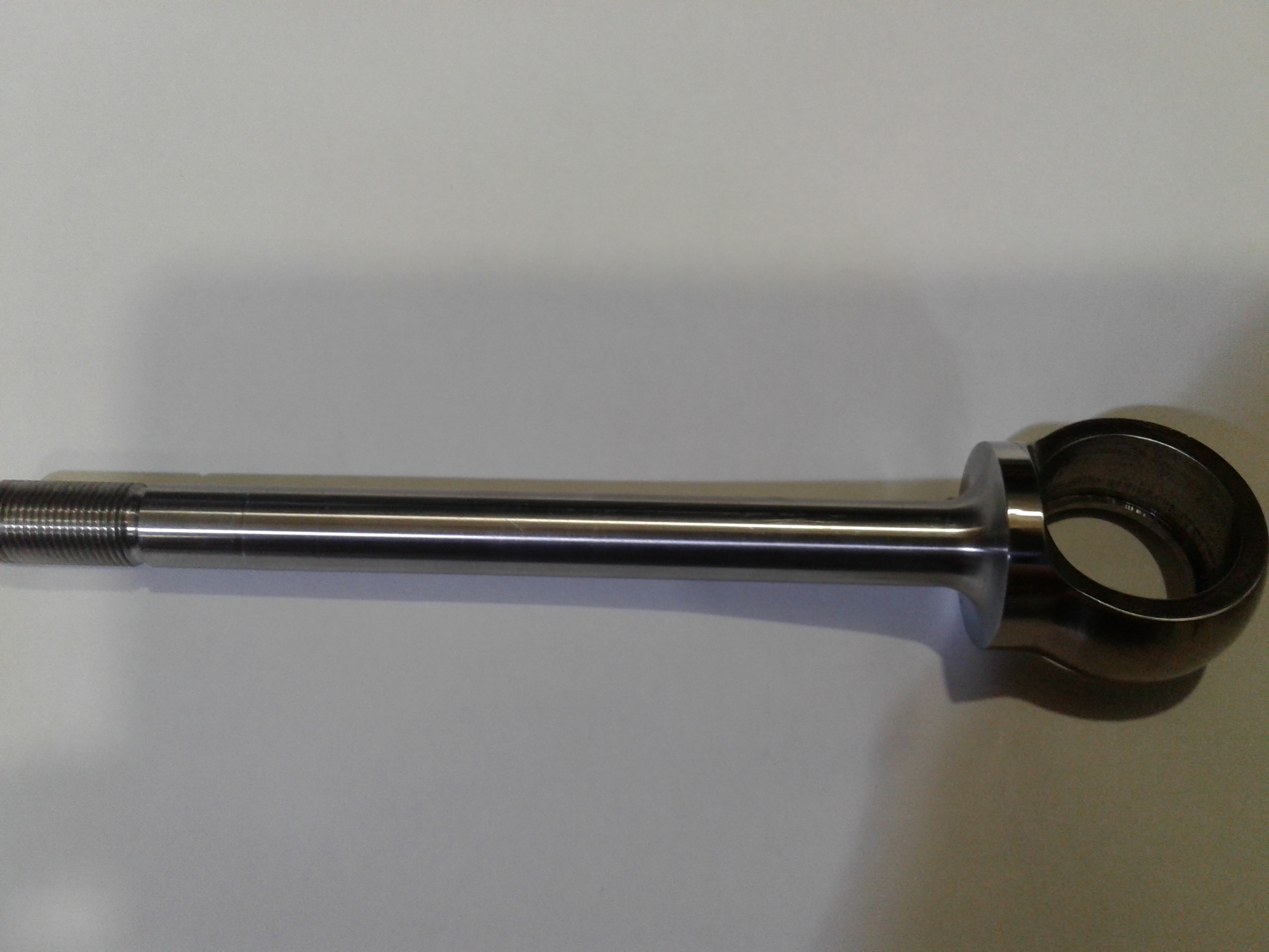
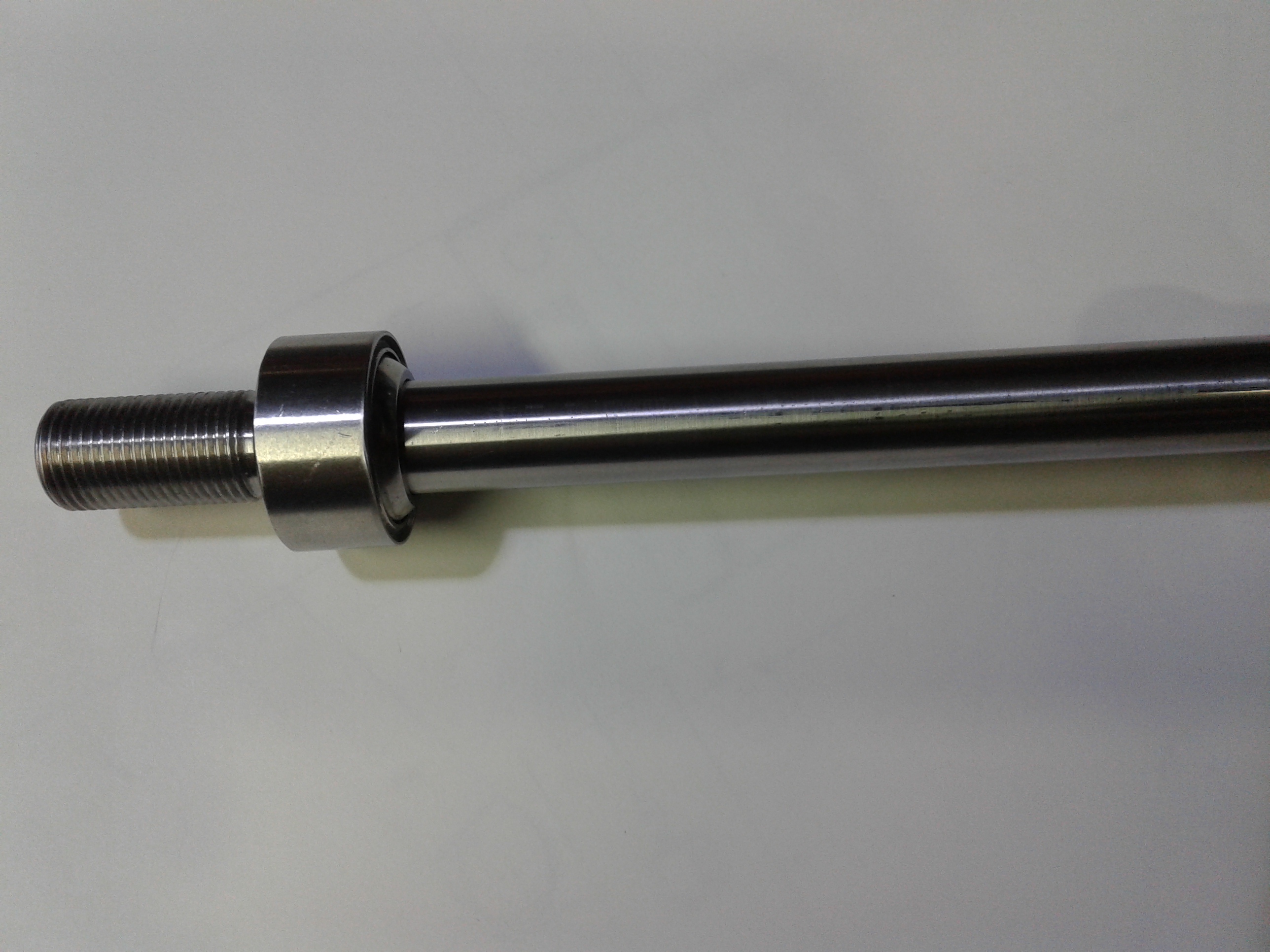
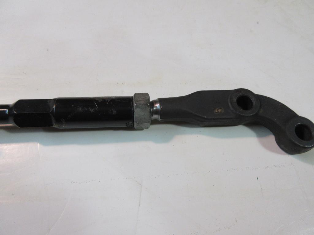
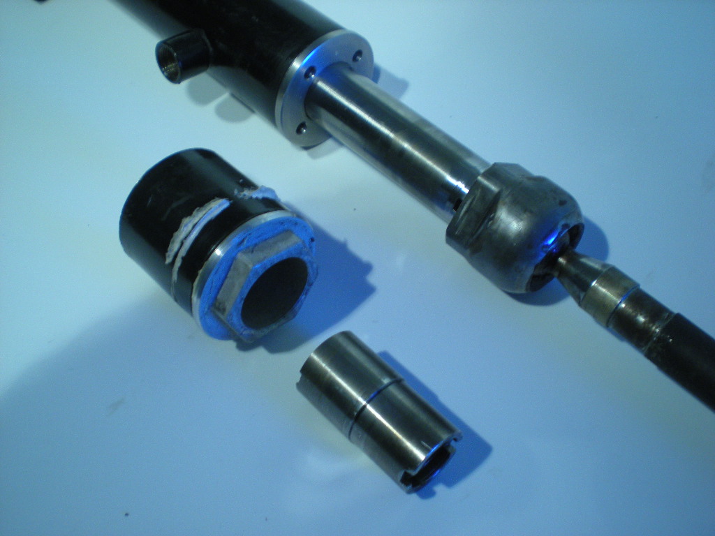
The counter bore on the left. What was removed. The pin spaner cap on the right.
-
I dought it will brake right away. I think the input bearing will start winning after 20,000 miles. That gives me 4-5 years. A T56 was my first thought with a bell housing cut from billit. In searching for one I found a T45 and started the project. I cut 240 hull in sections to use for mock-up and found th T45 a tight fit. All ready thinking of the extra weight the motor added. I started looking for a 280ZX T5 thinking the tail housing mount, shifter and driveshaft might be a bolt in. The T5 I am using was puchesed for the input shaft and gear set to be instaled with a 280ZX tail housing and mainshaft. I never found a ZX T5 or info about the parts swap between the two. So at this point the Mustang T5 is what I am working with. If I brake it I will go back to the drawing board. The T45 is in storage with a just in case.
-
I have 4 cylinder, a 6 cylinder, and a V8 now it's time for a V12. I purchased a 750i awhile back for $500 running driving. when I puled the engine out, I found the bell housing very large. There is also the oil pump and sump to be move to the rear. Recently I have found 3 MB V12 in the self serve junk yards and 2 more BMW's. A MB V12 was purchased for $400 complete. The MB V12 oil sump look's like a better fit, and the bell housing is small. Problems are over all hight, rear exhaust manifolds and no flywheel for manual. The auto flex plate has a bolt on ring gear with the cut out windows for the crank sensor's and a thick clamp ring on the crank. So the stock ring gear and fly wheel bolt's will work for a custom FW. Clutch size is 10.5". The bell housing is cut off the front of the auto trans just behine the ring for the pump. One side of a plate was turned down to fit tight in the pump ring bore, With the same set up on the lathe the hole for the T5 was bored.The bolt pattern for the pump was transfered to the plate, drilled and counter sunk for Flat head scoket screws. The plate is mounted to the bell housing and machined parallel to the engine side. Factors that make up the lenght of the bell housing are ring gear clutch and piolit bearing. This means a long input shaft lenght. Looked for a ZXt T5 never found one to check out. If you have a ZX with a T5 and rear steering this swap might be a winter project. Found a T45 (the 5 speed version of a T56) it is big and 125 Lbs. Ended up with a T5 at 75 Lbs. from a Mustang 3.8 V6. A Hyd. cluch release bearing from a Camero T5. A Mustang clutch. I am starting work on the cross member now. Clearnce for the Miata Power steering at the side of the oil pan has to be worked out before I can finnish it. Next will be shorting the oil sump, moving the left throdle body foward and the exhaust. Last is finding a EFI to run it. When all the Junk Yards are in alinement with the Swap Meets I will have a Rat Rod
-
Modifyed Miata power steering rack for 240Z
BoonZ replied to BoonZ's topic in Brakes, Wheels, Suspension and Chassis
Lurcher, Most of the Z's I have driven had a lose feel in the center, some cars had a shimmy at speed. Adjusting the rack only made for hard steering. Looking at the racks the gear teath are worn beond service at the center.The fix was to shift the rack to one side. 74_5.0L_Z, Measument was taken with a caliper ±.001. The production tolorance of the rack is unkown as are production line changes. A 25' tape measuer has a tolorance of ±1/32 over all.I have checked tapes using a master scale and found that a good tape is hard to find. No matter the name on it. The 12' and shorter tapes are printed with a wheel, longer ones are printed with a belt. The belt is prone to strech, slip is a problem for all. Worst one I found was off by1/16" at 24". The rack I measured had no stops between the locknut and housing. do not know if this was stock or not. I went and checked a rack from a 72 with stops It is 4.744", Looks like I have some extra travel, maybe this will help me when drifting at the Auto-X, or maybe shorten the center to center some more.I have a 71 I bought from the orignal owner, I will check this one as I know it to be orignal. Looking at the 240 rack if it were cut off at the stops driled and taped for new style tie rod's of 3/4" center to face. Center to center will be about 22.5"no lss of travel no housing machining. JMortensen, Just copying what was there. Right now I am working with the cross member/engine swap and needed the rack for mockup. MikeMileski, Same center to center, The 92 rack has a ball bearing on the end of the pinion (97 is a needle bearing) the bushing is metal and much longer(97 is plastic) Moving the racks by hand the 97 has more drag. -
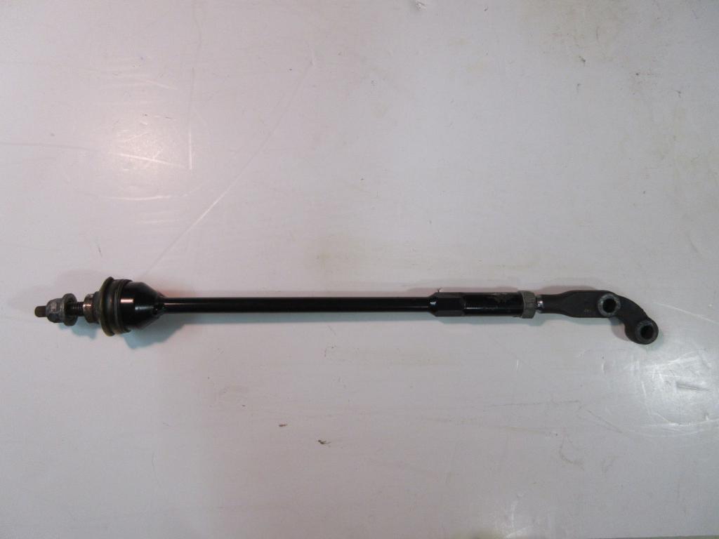
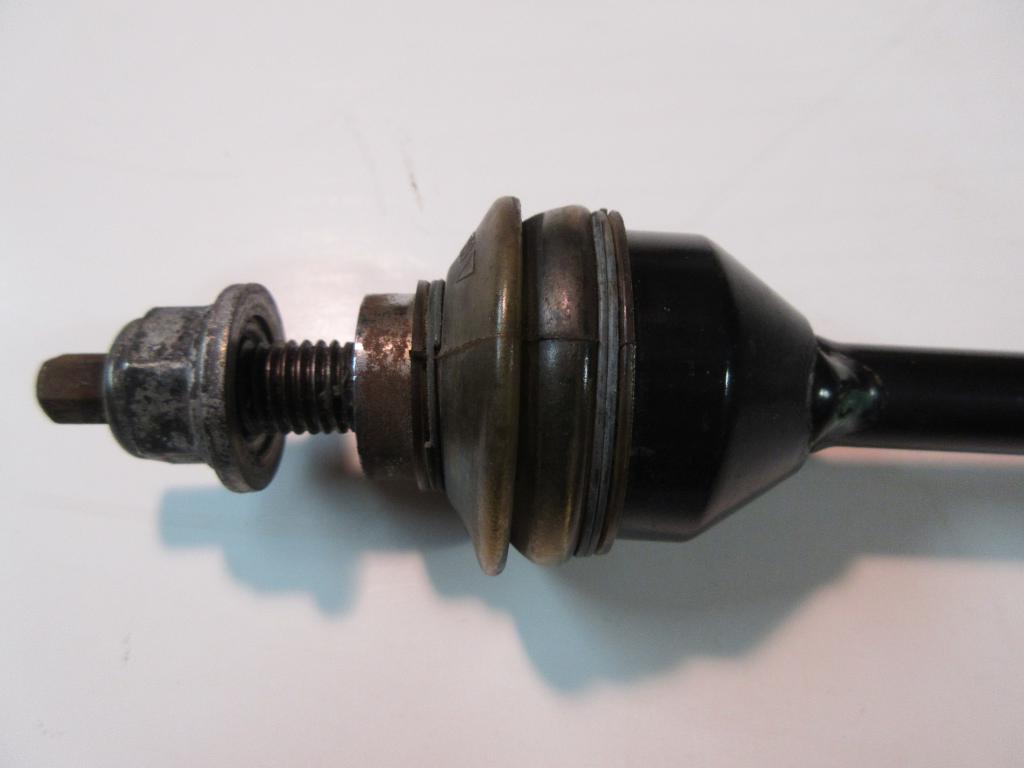
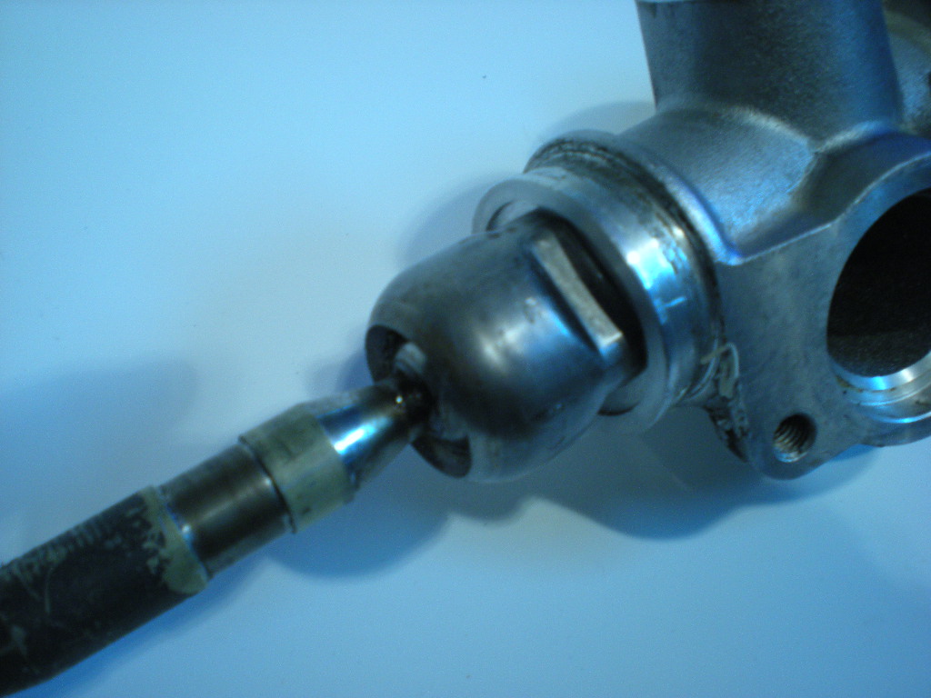
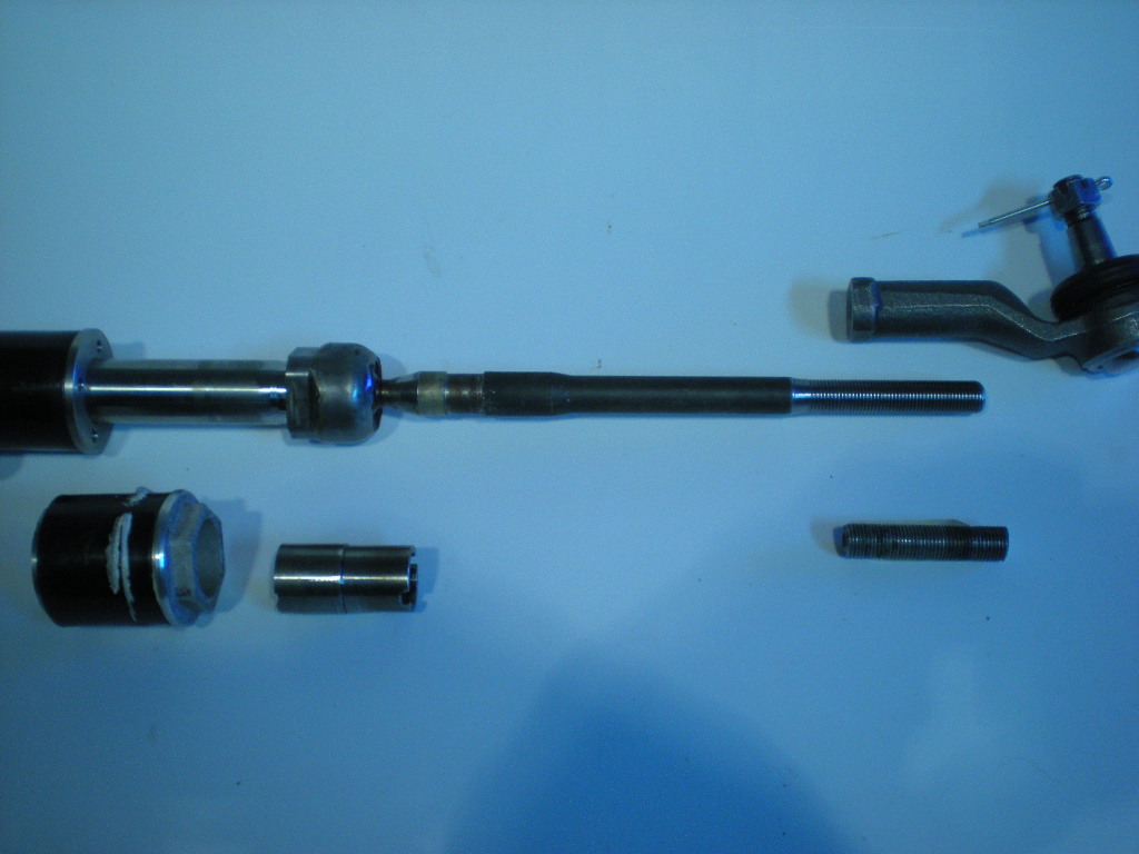
This is not a how to,It is what I have done. Mesuring the 240 rack I came up with 24.230" from center to center of ball scokets (iner tie rod pivot point) and a travel of 5.125". The pinion is 7.5" from the center of the housing. The Miata rack's I reviewed are from a 92 and 97. The 92 has a vavle body cast with the gear case and is held togeather with C-clips. This makes it harder to modify. The 97 has a vavle housing bolted to the gear case and the end cap screws into the housing. This is what I will cover here. The Miata rack is 26.040"center to center of ball scokets with a travel of 4.704". The pinion is 8.75" from the center of the housing. Ball scoket threads are 17x1.0MM RH. Center of ball scoket to mating face of rack is (including lockwasher) .740".The travel is limited by ball scokets contact with the housing. Removing the ball scokets allows more travel that is now limited by the distance between the fluid lines less the with of the piston inside 5.354"-.287"=5.067" max travel for this rack. Not as much as the 240's 5.125",But with power steering I will go with shorter steering arms to make up for it. To get Center to center of 24.230" I removed 1.812" off the right end of the rack remachined the end with the exception of the lenght of the small OD witch was shortened to .25". This aera and the vent hole must be polished to prevent seal damage. The housing was cut down 1.582" on the right side and remachined. The thread is 40x1.0MM RH, I used 1.575"x24TPI RH (My lathe is english) A new shorter end cap was made alowing an extra .385" travel. It stops the piston befor it blocks the fluid port on the left. Using a face pin spaner insted of a hex alowes more of the housing to be left in place for the rubber mount. This made up for cutting less off the housing than the rack. On the left end of the housing a counter bore 1.5" DIA x.150"deep alowing the ball scoket to travel inside the housing,and the piston to travel to the edge of the right fluid port. The tie rod's were cut down 2.25" and threaded 12x1.25MM RH. Miata outer tie rod's will be used. I now have a rack with the same center to center as the 240z, and a travel of 5.067". Other problems to address will be the pinion is now 6.562" from the center of the housing (15/16" closer to the motor), steering shaft and mounting made.
-
What fuel system are you going to use?