cheftrd Posted January 26, 2006 Share Posted January 26, 2006 A couple of points here that I feel need some clarification. Some of you guys already know this stuff, and I don’t mean to beat the proverbial “dead horseâ€, so please bear with. ITB’s are not conducive to power production. The reason for using ITB’s over a conventional throttle/plenum is improved throttle response/control. Improved throttle response/control is good for circuit cars. Circuit racing is what the GT-R was designed for, not a no holds barred drag racer as we would like to believe. An engine will make more power when it doesn’t have an 8mm shaft running through the middle of the port, obstructing air flow and creating turbulence, six to eight inches from the intake valve. Most of the drag (uber power) RB26’s use a large single. Aftermarket twin throttle intakes serve the same purpose, but with an attempt to better distribute the air between the front and rear cylinders. Indicated AFR (according to the meter, wideband or otherwise), is affected by many variables. Complete or incomplete combustion (read clean or dirty combustion) knock, and cylinder head temperature are a few of these variables. Early on in the RB26 (or any RB for that matter) aftermarket modification race, it was found that even with no audible knock and AFR in check, #6 cylinder would consistently fail ring lands at elevated power levels. With the addition of forged pistons, power could be increased, but #6 will still show failure in the form of burnt (melted) pistons and squish pads while other cylinders may appear unscathed. Damage to other cylinders could also be present, but it is progressive from front to rear, with the rear always suffering the worst. Many “builders†assumed that this was because the rear cylinder must be getting more air and therefore be lean. Sure enough, individual cylinder testing showed AFR increasingly lean from front to rear. Many assumed it was a bad manifold design. However, even with the addition of an aftermarket manifold the problem persisted. One look at the stock RB26 plenum and any reasonably mechanically inclined person will know that the hyper-breathing #6 port phenomenon is a myth. Common sense says that there is no way that cylinder is getting more air than the others through the twisted, choked, compromise of a port runner that was made that way to clear the clutch master cylinder; no matter what individual cylinder AFR comparisons say. Here’s what I found through a little testing: The RB26 runs progressively hotter from front to rear. By third gear on a full throttle pull with a 500hp motor, coolant temps in the #6 combustion chamber area can be smokin’ (or steamin’ if you like), while the overall coolant temps are in check on the gauge. High cylinder head temps contribute to many things; two of which are more complete combustion and knock inducing hot-spots. More complete (and hotter) combustion will show as leaner on the AFR meter, and knock will destroy pistons. See where this is heading? By adding an additional coolant outlet to the rear of the head, the temperature in the #6 combustion chamber area came almost in line with #1. AFR differences between #1 and #6, and exhaust temperature differences between #1 and #6 were negligible. Adding three additional coolant outlets like the Exvitermini GT-R is also an option, and will keep the entire head cooler. I haven’t personally done this mod yet, so the jury is still out on the disparity between front and rear cylinders. Quote Link to comment Share on other sites More sharing options...
hat1324 Posted January 26, 2006 Share Posted January 26, 2006 mind if I take this over to racebread? Quote Link to comment Share on other sites More sharing options...
thehelix112 Posted January 26, 2006 Share Posted January 26, 2006 Matt, Makes sense. Thanks for the informative post. Dave Quote Link to comment Share on other sites More sharing options...
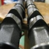
RB26powered74zcar Posted January 26, 2006 Share Posted January 26, 2006 This is the mod Matt's refering to on the head, allowing more water thru the head... This is the GT cooling setup you see on some of the race cars such as JUN and the Exvitermini stuff. Using a mill you plunge down to the water passage in the manifold between ports 1-2' date=' 3-4 and 5-6. I then welded a -8 male an fitting to the manifold. This will run to a reservoir that will also be a merge for the water returns for the turbo's. From there it will run back to the radiator. Basically, all the water leaves the head and runs to the front of the intake via the log on the bottom. To help expidite coolant flow from the head we supplement by adding additional outage points from the manifold. It would have probably looked a bit more clean on the bottom of the manifold, but might as well show it off.[/quote'] At the bottom of this thread, James explains the mod> http://forums.freshalloy.com/ubbthreads/showflat.php?Cat=&Board=UBB4&Number=67936773&page=0&view=collapsed&sb=5&o=&fpart=1 Quote Link to comment Share on other sites More sharing options...
cheftrd Posted January 26, 2006 Author Share Posted January 26, 2006 mind if I take this over to racebread? That's cool. Quote Link to comment Share on other sites More sharing options...
Guest JAMIE T Posted January 26, 2006 Share Posted January 26, 2006 Very good post Matt! Very informative. Quote Link to comment Share on other sites More sharing options...
cheftrd Posted January 26, 2006 Author Share Posted January 26, 2006 The 26 I'll be putting into an S15 shortly will have this mod done like Joel's car. This is an uber-expensive engine, so I really hope it works!! Quote Link to comment Share on other sites More sharing options...
240zwannabe Posted January 27, 2006 Share Posted January 27, 2006 what did you use to put holes in the head with? might just try this on the future l28et build Quote Link to comment Share on other sites More sharing options...
Ed260Z Posted January 28, 2006 Share Posted January 28, 2006 Is this completely home grown, or is there a co. that makes a kit for this mod? Quote Link to comment Share on other sites More sharing options...
turbo_fb Posted January 29, 2006 Share Posted January 29, 2006 The intake of water is placed on the front side of the manifoil, so by mounting 3 extra water outlets on the manifoil, wouldnt there be less water cooling the end of the engine? Just circulating in the first part of the engine ? Quote Link to comment Share on other sites More sharing options...
cheftrd Posted January 29, 2006 Author Share Posted January 29, 2006 The intake of water is placed on the front side of the manifoil' date=' so by mounting 3 extra water outlets on the manifoil, wouldnt there be less water cooling the end of the engine? Just circulating in the first part of the engine ?[/quote'] The coolant is pulled from the bottom of the radiator by the pump. From there its pushed into the left side of the cylinder block, up through the head and out the right side of the haed and back to the top of the radiator. The three additional outlets let more coolant flow from the engine and bleed air from the system. Quote Link to comment Share on other sites More sharing options...
turbo_fb Posted January 29, 2006 Share Posted January 29, 2006 The coolant is pulled from the bottom of the radiator by the pump. From there its pushed into the left side of the cylinder block, up through the head and out the right side of the haed and back to the top of the radiator. The three additional outlets let more coolant flow from the engine and bleed air from the system. Thx. Makes it more understandable now. Quote Link to comment Share on other sites More sharing options...
Lunar240z Posted January 29, 2006 Share Posted January 29, 2006 i'm really interested in seeing how it looks all plumbed. Quote Link to comment Share on other sites More sharing options...
Ed260Z Posted February 4, 2006 Share Posted February 4, 2006 Any chance of someone spelling this out for us step by step, and posting a How-To on this? This sounds like a really good mod for the engine. Quote Link to comment Share on other sites More sharing options...
BirdmanZ Posted February 4, 2006 Share Posted February 4, 2006 i second that. i definetly want to do this to mine Quote Link to comment Share on other sites More sharing options...
Ed260Z Posted February 6, 2006 Share Posted February 6, 2006 I went onto the Ex Vi Termini site, and if you go through all of the pics you can piece together what they did. It looks like they used an over flow canister with 3 inlets on it, and a 1-1.5" outlet. I'm assuming that you would plum this outlet to the outlet on the block, so that it will circulate with the rest of the coolant. From J. Soileau RB26zcar's pics it looks like you need to go through the ITB's, but I hope someone can clarify this. Quote Link to comment Share on other sites More sharing options...
turbo_fb Posted February 9, 2006 Share Posted February 9, 2006 Here is the best pic from Xvit that I could find. Red is the 3 outlets from the manifoil. Blue and green explains itself. I guess there is a bottom hole on the tank - Mint color Orange is second hose on the tank in the back. I could not find out where it is going. Quote Link to comment Share on other sites More sharing options...
Lunar240z Posted February 10, 2006 Share Posted February 10, 2006 It looks like the lower hose you were talking about goes to this other tank that's not visible in the other pics but in this pic it looks like that second line is another overflow line like the one coming from the radiator. Quote Link to comment Share on other sites More sharing options...
Lunar240z Posted February 10, 2006 Share Posted February 10, 2006 I think i've got it now. I did more searching on the exvit site, and i'm prett sure its another overflow line. i traced where i think the line goes. Quote Link to comment Share on other sites More sharing options...
240Z Turbo Posted February 10, 2006 Share Posted February 10, 2006 but in this pic it looks like that second line is another overflow line like the one coming from the radiator. The 3 fuel pumps probably run to it. Quote Link to comment Share on other sites More sharing options...
Recommended Posts
Join the conversation
You can post now and register later. If you have an account, sign in now to post with your account.