

tholt
-
Posts
17 -
Joined
-
Last visited
-
Days Won
1
Content Type
Profiles
Forums
Blogs
Events
Gallery
Downloads
Store
Posts posted by tholt
-
-
Thanks guys! I still haven't pulled the trigger yet, but I'm leaning towards the 2 disk 5.5 Quartermaster with the "rally" friction disc. It's supposed to be a little more forgiving of some slipping... It will require the anular TB, but one thing I might do after I give it a try, is to swap the clutch MC to a smaller dia. to provide a little more pedal travel. My car tops out at about 20 in 1st, so the launch will probably be pretty painless once I get used to it.
It's good to hear the flexplate setup is the lightest, especially on top of being the cheapest .
...and I remember you Eric (correct?). I was very happy not to work grid for the SAE guys this year! Way to much drama!

Tom
-
Hi gang,
I am planning to upgrade the clutch on my dedicated autocross F Prepared 280Z and was looking for some experienced advice. I currently run the Nissan Motorpsort 11lb flywheel/Centerforce bi metal PP/solid bronze puck disk setup and it has been bulletproof for over 15 years. The downside is the complete assembly weighs 23 lbs and I considering the 5.5 or 7.25 multi disk assemblies that weigh a lot less.
Is anyone running this type of setup and have any recommendations? Are you running the automatic flexplate or did you buy the custom flywheel? What about throwout bearings? Did you switch to an anular setup or can you keep the stock lever arm?
The few cars I have driven with a 5.5" clutch were a bitch to launch but those cars didn't have near as much reciprocating mass or torque as my Z, is the 7.25 better in that respect?
What about brands? I assume all of the major players are about the same. Are there any friction materials I should stay away from?
Any advice is appreciated.
Thanks,
Tom
-
Wow! You've been as busy as I have!
I went through a similar unsprung weight excercise, but took a different approach based on laziness.
In the front, since I had the upright removed and left the rest of the control arm intact, I weighed the control arm on the car, resting the end of the arm on the scale. Since I have a heimed front end, friction was minimal so I figured it would be close. so my numbers were:
Control arm with brake caliper - 16 lbs
Wheel+ Hoosier slick - 36 lbs
Upright + rotor - 30
Shock + spring - 8 /2 = 4lbs
So - 86 lbs on each front corner
In the rear I used a similar approach but there was a lot more friction in the control arm so there is probably a larger margin of error. I tried to bias the friction each way and took the average. So:
Control arm w/upright/half shaft and caliper - 40lbs
Wheel/slick - 36lbs
Rotor - 10lbs
spring/shock 8/2=4lbs
90 lbs per rear corner
We were pretty close in the front and I suspect the differnce in the rear is attributable to the halfshafts. Not sure where the CG of your CV joints are but my car using stock halfshafts the bulk of the mass is towards the diff so less outboard weight...
Getting back to motion ratios... Thanks for measuring that! I was planning to do the same excercise this weekend. I probably still will, but for the time being I had been using the inverse of the motion ratio as calculated by the Mitchell suspension software. That being .942 in the front and .876 in the rear. I am impressed with the presumed accuracy in the rear... our differences easily within the margin of error of my measurments or our probable camber differences. Not sure whats up in the front...
Tom
-
Has anyone calculated the motion ratio of the front and rear suspension on a 280Z and obtained an answer that you are have confidence in the accuracy?
Using a tape measure in the rear I have calculated a .82 MR. Measuring from the pivot to the base of the strut and from the pivot to the hub face (assuming zero offset wheels).
Using suspension analysis software (Mitchell's WinGeo), it shows a ratio of 1.142, which I assume is the inverse, so that would be .876
Does anyone have a good answer for comparison? How about a good sketch showing proper measurement and calculation? I need to go buy a book or two, but I want answers now!
I am planning to do some shock dyno testing and trying to get the suspensions natural frequency...
Thanks in advance.
Tom
-
On to Phase 2:
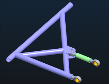
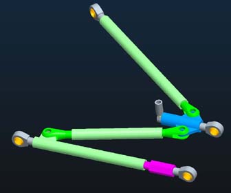
Okay... At first pass I'm not liking the forward toe link too much. The basic problem is the toe link really gets in the way of the sway bar link. I haven't figured out a good way to make that work yet other than ditch the sway bar or put the toe link at a bad angle. I did two iterations of this design. The simplest is shown below as LCA2-B (purple). It works the best of the forward link designs and mounts in the stock inner locations. It might be advisable to add one more bar from the inner bar to the toelink joint... but again no swaybar
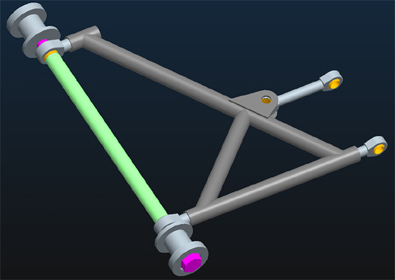
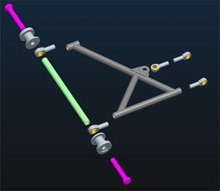
I tried another version using heims on the inner mount (LCA2)(gray), but it really didn't work. There was not enough room to fit two 5/8" heims end to end for the toe link. I do kind of like the inner mount concept though.... see the exploded view. This would use 3/4" bolts and heims with a section of tap tube tying it all together front to rear. I would have to make some aluminum bushings to support the bolts in the stock mount locations.
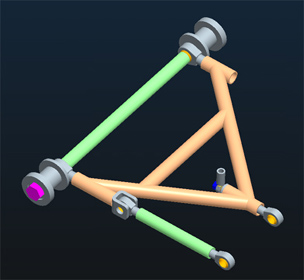
Next I looked at moving the toe link to the rear (LCA3)(yellow). I know this has some drawbacks based on our discussions, but it sure does work better from a design simplicity standpoint. It also lets me use the inner heim design from above. I need to evaluate just how big the drawbacks are to having the front outer mount fixed. It might be a little more tedious on the alignment rack, but probably not by much. I've already thought of adding spherical bearings on the inner bushings and using a fixed tube on the innner mount rather than the heims and that hasn't been ruled out, but it would be about 2X the cost.
Go ahead... tell me what you don't like! I can take it.
Tom
-
Okay... trying to get caught up here and my brain is really starting to hurt.
So, if I am understanding Dan's sketches and and the output of his spreadsheet, it says that if you have a 1 degree angle between the inner and outer control arm axis the amount of bind that will induce is about .025"...
That would be 1 degree of toe per side.... that's a LOT... The most I would ever try and run in the rear is about 1/8" per side, that would be about .3 degrees ( I would really only run about half of that). Using that number in the spreadsheet it says that the induced bind is only about .007" and it only varies by .0015" through 20 degrees of travel. If you loosen your camber plates the .007 will probably self adjust. Chances are the amount of bind we are discussing is way down in noise level or at least well within teh tolerance range. Unless of course your frame is way out of square and you are trying to use the adjustability to compensate...
I think I am on board for trying to build something like the arms Jon sketched... the rear suspension is already disassembled for a shock rebuild and the plan was already to build new LCAs. I'll be busting out the CAD soon with an intial design... stay tuned.
Tom
-
I've definitely seen Johns control arms... My only gripe is there is no provision for toe adjustment. I think I am leaning more towards something like the Arizona steel tube arms with it's adjuster but add heims on the inner mounts...
Tom
-
You finally made sense to me on you last reply Jon... Good point, but I think the thing that has probably convinced me to ditch the plan is the fact that the forward joint (blue) is only held by 3 rotataing points. In other words, that forward triangle is not a triangle. It's a quadrangle with a short leg running through the blue piece. The only thing that will keep that joint from rotating fore and aft is the friction of the clevis bolts. It might be sufficient to do the job, but when it slips it's going to get real weird real fast.
Maybe there is a reason that the car I saw this on is a perennial back marker!
Time to go back to the drawing board for a more conventional design.
Thanks for the reality check guys!
Tom
-
Like just about everyone else, I have an overwhelming compulsion to design and build my own rear control arms. My application is for an autocross only car, so keep that in mind as you pass judgement. It will never see the open road or >100mph...
That said, this is pretty much a direct copy of a setup I have seen on a GT2 Z and it hasn't fallen to the ground yet after several years of competition. Only the sway bar link has been added. I really like the total on-car adjuastability. One of my main goals is to facilitate as much track width/camber adjustment as possible from the bottom. Simply detach one end of the mid link and all heims can be adjusted. Toe can be controlled with just the rear adjuster.
The inner mounts will probably be a simple bolt-in frame that will locate the inner heims as close to their stock locations as possible. I will update as that get's developed?
Does anyone see any major concerns with this? It seems to be a proven design, but I could be wrong...
-
Hey Mark,
If you want to run Prepared with the 3.1... you can still run XP. You can turbo it, stroke it, V8 it, whatever! So long as it fits in front of the firewall, it's legal. (pretty much.) Don't spend too much time looking for sub 10" wide 16" slicks... they don't exist. There is no market for them, so no one makes them. That said the DOT-R's are not much of a step down. Especially if you are running on asphalt. For the slicks to REALLY show their strength you need some really grippy concrete or ultra grippy concrete (which is very rare). Many people in various prepared classes have begun to switch from the bias ply slicks to the radial DOT-Rs and I don't see that trend changing.
Another "plus" for XP is wheel widths and diameters are unrestricted, so if you decide you want to go up to 17" wheels, you do not incur any weight penalty.
If you ever do make it to true slicks, living in the south, I don't recommend going any softer than Hoosier's R35 compound (or equivalent), at least during the summer. They can overheat pretty quickly. Even the Kumhos prefer to be cooled off between runs when it's really hot.
Have fun with your car and if you can, try and make it over towards Tampa, and try and catch a ride with John Thomas in his 240. He will inspire you... to either go faster or quit... either way, you will be inspired!
Changing subjects a bit, earlier someone was saying I was running the 23.5x11.5x16... That was only for one season. I'm back on the 22x10x16. Both tires are speced to run on a 10" wheel, but the bigger tire is at it's lower limit. I don't think the wheel width was too big of deal as much i just didn't like the transient response of the taller tire. The 22x10 is just so responsive, that i was never happy with the bigger tire. The gains I may have made it ultimate lateral grip were more than offset by the slow response time. That said... I may try switching to the new 23x11x16 radial slick... we will see!
Tom
-
That's the number one online question I get about my car. I wish I knew the answer. They were on the car when I bought it. I want to say they look like the ones Arizona Z car sold, but they got out of the fiberglas business. I think Motorsport Auto used to sell something very close also, but I don't see them anymore... So bottom line... I don't know.
Sorry...
Tom
-
I don't think I want to tear into it that deep... I was planning to add heim mounts on the end links, but that is about as fancy as I plan to get for now...
Tom
-
Jon,
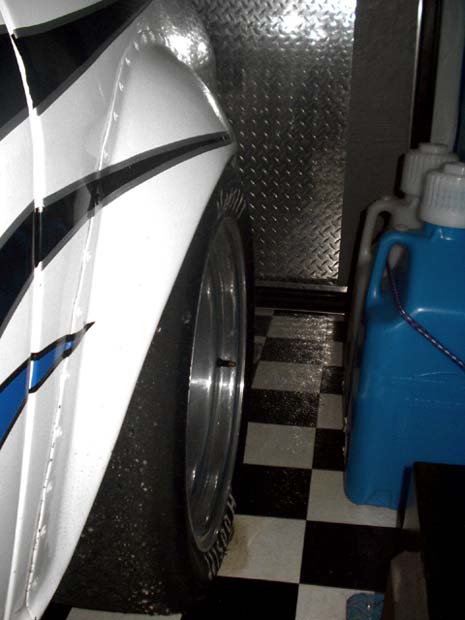
I'll second what Pete says and recommend waiting until you are on the ground to make your final decision... That said, I have the 3" flares and I am running 16x10" wheels with 5" back space and have run the bigger 23.5x11.5x16 Hoosier slicks with no problems. I had about 1/4" clearance between the tire and the springs, and after running numerous events I did find a small black smudge on one rear spring from a minor rub. I couldn't find a mark on the tire, so it was a very minor kiss or two during extreme conditions (like when I would get on 2 wheels at mid turn over a nasty bump). I never saw any sign that the tires touched the flares, however my flares have a bit of extra clearance ground into them at about 2 o'clock (on the right side, 10 o'clock on the left side) as you face the wheel. The fit of the tires in the fenders looked great, very full muscular look... I've attached a couple of pics that show how it fit with those big tires.
You don't say what size wheels you are going to. Pete mentioned 10" wide... If you are planning on 15" wheels, you may need to keep your section width smaller than the Hoosiers I mentioned, to maintain clearance from the spring. If you go with 16's I don't think you can fit anymore rubber under the car than those Hoosiers. If you go bigger in diameter on the wheel, you may be able to get away with a little more sidewall buldge on the inside, but you might have to give up a little overall width on the outside to avoid the flare.
Hope that helps a little!
Tom
-
Sorry for dropping out for a few days guys... and Cary, I'm extra sorry I caused you to actually read the rules!
Now that you have read them, I agree with your interpretations... The question of WHERE the wheelbase should be relative to the chassis is a whole other can of worms, since the drawings someone else posted in another thread dimension the wheelbase from the bumpers. So long as you have a wheelbase of 91.7" or less and the wheels look like they are where they are supposed to be, I can almost guarantee you will never have protest problems...Back to my car and what I am planning based on our discussions...
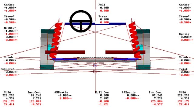
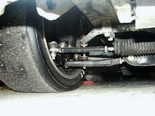
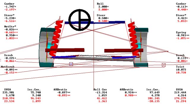
Playing with the geometry software, and assuming a fair amount of error in what it is telling me I am planning to raise the inner pivot by about 1.25". My current control arms are pretty close to level, but even with the 1" bump spacers the inner pivot is about 1" below the balljoint (the balljoint was one of the harder dimensions to guess since it is hidden by the rubber boot)(pic below). If I can get the inner pivot up above the ball joint by a 1/4" that brings my roll center to about 2.5" above ground and keeps it within about 15" of the centerline in a roll state. Which is about a 25" improvement over where I am now! If I move the inner pivots inboard, I reduce that 15" by about 2" for every 1" I move inboard, but going inboard forces more extensive modifications of the crossmember and probably screws up my bumpsteer in a way that is not easily corrected. It would also mean making longer control arms... So I am thinking the inboard move is probably not worth the trouble.
Next on the change list is moving the upper strut mount back to gain some caster. I am also planning to go with adjustable TC rods to fine tune the caster. My wheel base is kind of short right now (about 1/2" under spec at 90.2"). So moving the upper mount back 1/2" and the balljoint forward 1/2" I should be sitting at around 5 degrees of caster which is a good start.
I've included some screen shots of the current and proposed geometry (if I got the files small enough) showing the how the compare sitting straight and with 2degrees of roll and a moderate amount of steering input. I find interesting that the roll center changes sides as you go from below to above ground level.
Tom
-
Thanks for the feedback guys! I can't believe I never realized how much info was on this forum... I've had a login here for years, I must have posted more than once before.
Allright... so I think adding caster is a given. I will just have to sneak up on that to find the right amount. I am currently running bias ply slicks but I may try switching to the Hoosier radial slicks. That might play into how much I want. Looking at the difference in camber gain I may want to start low with the bias tires and add more if I want to try the radials.
Jon, on the rollcenter and stiff springs comment, I am currently on 400 lb springs all around. If I pull the RC up above ground, is that going to drive a change to softer springs?
I've got this nagging fear that if I "improve" the suspension too much I won't be able to drive it. I've had pretty good luck with the less than ideal setup, for a long time. I'm not sure I can adapt at this point!
Tom
-
I've been reading all of the very good (and some very long) threads on suspension mods and was curious if there was any firm concensus on optimizing the suspension mounting points on a dedicated race car?
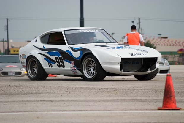
Many of you are familiar with my car ( http://sth2.com/Z-car/ ), if not, it is a purpose built F Prepared 280Z autocross car and about the only area where the car is not fully optimized is in the suspension geometry. That is my project for this winter.
I started by using some suspension analysis software and took my best shot at measuring the current setup. I think I did a pretty accurate job, using level setup stands, laser levels and virtually every measurment tool in my garage. The results were well below ideal. My front roll center is about 1" underground and jumps around laterally about 4 feet either direction when I induce about 2 degrees of roll. The camber change is going a good way into positive with that much roll. The rear is not as bad with the stock control arms, the RC is about 3.3" above ground and only moves a about 7.5" from side to side in roll...
So my main questions are:
1) Is there concensus on where the pickup points should be on a very much lowered car? Front and Rear...
2) I've read the threads on TC rods, but didn't get a solid feel for the benefit of moving those points. I played with those points in my suspension software but didn't see things change much. What am I missing there?
3) Is there a downside to increasing the length of the control arms? Provided I have clearance, I don't see a negative. Is there an area I need to pay attention to to avoid binding?
4) Caster. I've never had much, mainly because I have never made any modifications to make it more adjustable. Currently I only have about 1.25 degrees. I willing to take the plunge and try this stuff, i hear it can work wonders on turn in! Any recommendations on how much I want?
That's "all" I can think of right now, but I am sure I will think of more as we go! Thanks for any help.
Tom

Ford 8.8 IRS swap v2.0
in Drivetrain
Posted
Just curious how you plan to mount the front? Have you shared any designs yet? I assume a new crossmember with mounting arms reaching back? I am working on the same project myself and looking at other efforts I haven't seen a really strong solution yet.
Tom