
grumpyvette
-
Posts
3570 -
Joined
-
Last visited
-
Days Won
10
Content Type
Profiles
Forums
Blogs
Events
Gallery
Downloads
Store
Posts posted by grumpyvette
-
-
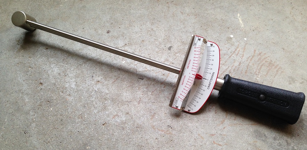
youll want a decent torque wrench in fact you really should have two,THIS BEAM STYLE TORQUE WRENCH IS THE TYPE TORQUE WRENCH YOU WANT TO CHECK ROTATIONAL RESISTANCE
 BUT NOT WHAT YOULL USE TO TIGHTEN HEAD BOLTSHUSKY $88 (worked rather well, over all I was pleased)
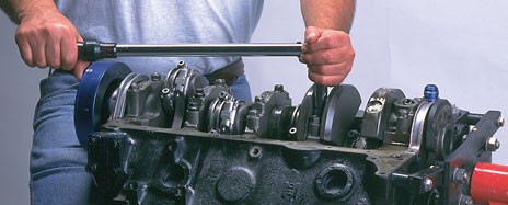
FOR HEAD BOLTS AND MAIN CAP STUDS ETC.
-
-
hey guys I'm looking too buy a lift for my shop, I'm thinking about a 4 post lift but want some ideas and feed back, before I buy any liftfirst point!be aware that theres a significant percentage of LOW PRICE,VERY LOW QUALITY, IMPORTED CRAP for sale and companys that are basically scams, so Id strongly advise dealing locally if possible, or at least with a well known national firm with a long standing reputation and asking lots of questions, getting answers in writing and contacting the local better business bureau, looking for complaints, and be damn sure to pay with a credit card so you have some recourse if the product is never shipped READ THRU THIS THREAD CAREFULLYId also point out that a 4 post lift is basically designed for easy on & off access and car storage, and while it will allow you to work on much of the car a TWO POST LIFT allows far easier access to the wheels and suspension, and in many cases the exhaust and drive train is a bit less easily accessed with a 4 post lift.a properly installed 2 post lift needs 6"-8" of concrete floor thickness to firmly anchor it, a 4 post will require less floor thickness, but there are HUGE DIFFERENCES IN LIFT STRUCTURAL STRENGTH AND MATERIAL QUALITY, the LOW PRICE IS THERE FOR A REASON, and your LIFE depends on its structural strength and design, saving $700-$1500 on the price if your car falls on you will be a really stupid move if you get seriously injured or killed when it fails, due to marginal strength or bad design.
-
if your willing to read through a few linked threads, and sub links I,m sure youll find all the info required
http://forum.grumpysperformance.com/viewtopic.php?f=55&t=109
http://forum.grumpysperformance.com/viewtopic.php?f=55&t=1790
http://forum.grumpysperformance.com/viewtopic.php?f=55&t=5229
http://forum.grumpysperformance.com/viewtopic.php?f=55&t=1639
-
now I'll admit I have limited experience with the , imports and z cars , having only helped on a few , maybe a dozen v8 conversions and generally build big block muscle cars , like GTO,camaros novas ,corvettes, and street rods like t-buckets and vegas with big block engines, but Ive certainly shredded my share of 10 bolt, and 12 bolt chevy and a few 9" ford differentials in the process and learned what parts hold up as a result. Ive darn sure shredded my share of corvette IRS differentials and half shafts, so any serious race car I build has a dana 60 rear differential custom fitted
http://forum.grumpysperformance.com/viewtopic.php?f=71&t=1282&p=36502&hilit=dana+differential#p36502
http://forum.grumpysperformance.com/viewtopic.php?f=71&t=1934&p=5126#p5126
-
looks like a real nice improvement thats been done well!
-
Id point out that one factor many guys over look that you constantly hear about the "MASSIVE TORQUE"
the most powerful TPI was the 1991 version
"In the 1991 Chevrolet Corvette, the L98 has a compression ratio of 9.5-to-1. Compression ratio lists the difference between the largest capacity of a cylinder and the smallest capacity, as the piston moves from bottom dead center on the crank stroke to top dead center on the crank stroke. In this engine, the mildly high compression ratios (considering the crappy gas available) mean that the engine could produce 245 horsepower at 4,000 rpm and 340 lb.-feet of torque at 3,200 rpm."
the LT4 only made 330hp/340ft lbs of torque
http://www.corvetteactioncenter.com/specs/c4/1996/lt1lt4.html
both engines are PITIFULLY WEAK compared to what you can build from a basic SBCyes we are all faced with working with limited budgets, obviously some far more limited than others but getting 450hp and 450ft lbs out of a properly built 383-406 sbc is not an un -obtainable goal
HERES SOME EXAMPLES
http://forum.grumpysperformance.com/viewtopic.php?f=69&t=3814
http://forum.grumpysperformance.com/viewtopic.php?f=44&t=38
http://forum.grumpysperformance.com/viewtopic.php?f=87&t=10377&p=42862&hilit=215cc+vortec#p42862
http://www.airflowresearch.com/articles/article155/A-P1.html
http://www.airflowresearch.com/articles/article085/A-P1.htm
http://www.airflowresearch.com/articles/article031/A-P1.htm
http://forum.grumpysperformance.com/viewtopic.php?f=55&t=10494
http://forum.grumpysperformance.com/viewtopic.php?f=32&t=430
http://forum.grumpysperformance.com/viewtopic.php?f=69&t=10152
http://forum.grumpysperformance.com/viewtopic.php?f=69&t=7771
http://forum.grumpysperformance.com/viewtopic.php?f=52&t=5078
http://forum.grumpysperformance.com/viewtopic.php?f=69&t=1040&p=1943#p1943 -
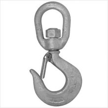
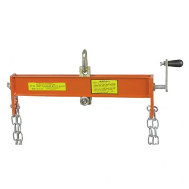
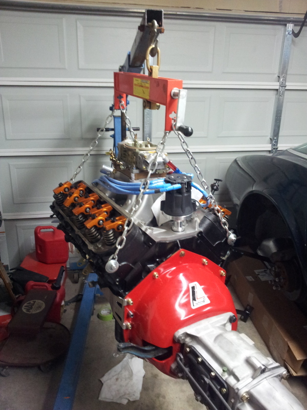
While were talking about the larger shop tools here, If you don,t have a swivel hook,or engine leveler/tilter, trust me it makes the job far easier, to have both
once you do youll wonder why you ever attempted the job without those accessories, without the swivel hook the engine constantly wants to swing back to one location, it fights you constantly, the tilter makes clearing and indexing the engine angle so much easier
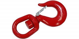
buy the 1.5-2 ton rated hook for your engine hoist and grease the swivel center pin on the hook
http://www.mfrexpress.com/alloy-swivel-hoist-hook-crane-hook-safety-latch-15-ton-p-699.html
adding a swivel like this between the leveler and crane GREATLY AIDS THE ENGINES REMOVAL, DON,T GET STUPID or CHEAP, GET THE 3000lb-3500lb rated one not the 1200lb size (REMEMBER YOULL BE UNDER THAT ENGINE SOMETIMES)
the picture above can be used as a teaching aid, this guys got the engine tilter he needs but its mounted with the tilter too far above the carburetor, limiting the distance the engine can be lifted above the fenders there should be about 2"-3" between the carburetor BASE MOUNT ON THE INTAKE, tilter at most,with the carb removed and the intake opening duct taped closed and lower edge of the engine, intake carburetor mounting pad and having the distributor still installed is still a small risk, that, is best avoided as it could be damaged, its best removed for safety, but the picture also does not have the swivel,hook, and hes using it with the crank handle at the wrong end as it will hit the wind shield in some applications while cranking in that location, rather than having the crank face the crane like it should
http://www.mfrexpress.com/alloy-swivel-hoist-hook-crane-hook-safety-latch-15-ton-p-699.html
I think youll find a properly installed swivel hook increases the cranes lift distance as the hook loop can be supported by the bolt thru the crane beam or a screw link and hooked directly into the engine leveler,either option is likely too be shorter than the current few chain links, IN ANY CASE ITS AN OPTION ALMOST ALL MY FRIENDS, AND I , NOW SWEAR BY AS A MANDATORY ACCESSORY if you get a spare $20 or so, and have the time to order one, I think youll find its money well spent. -
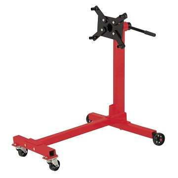
while price alone is not always a good indicator of quality its usually a good bet that the smaller and cheaper engine stands with the smaller wheel bases, like this
http://www.harborfreight.com/1000-lb-engine-stand-69520.html?hftref=cj
ARE less stable, with the identical engine mounted on them, and that the slightly more expensive stands, that have a larger and wider foot print, like this
http://www.harborfreight.com/2000-lb-foldable-engine-stand-69521-8970.html?hftref=cj
are harder to tip once the engines mounted, due to simple leverage and physics
and that every engine stand Ive seen for sale for under $300 has had really crappy low quality and small diameter casters, and few have caster roll locks, the main point I was trying to make here was that upgrading the casters to the larger size, and better quality and selecting an engine stand with a wide stable base to convert to the use of those larger swivel casters makes it far less likely to be effected by running over minor trash, or floor seams.
-
BTW,how many guys own basic machine tools like a decent welder and drill press , air compressor , etc/
http://forum.grumpysperformance.com/viewtopic.php?f=60&t=10392&p=43018&hilit=miller+252#p43018
http://forum.grumpysperformance.com/viewtopic.php?f=27&t=24
http://forum.grumpysperformance.com/viewtopic.php?f=27&t=970
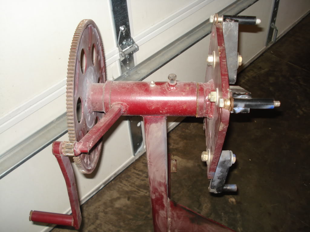
heres a darn impressive and logical custom welding project, I found posted on a different site and finding an older flex-plate or flywheel and a spare starter and gear for use with the engine stand as a gear drive and adding some custom crank handle, makes the stand more useable.
now I don,t know why I didn,t think of this, its a rather simple modification with easily obtainable components that would make using an engine stand easier.
the pictures, showing what needed to be done is rather self explanatory
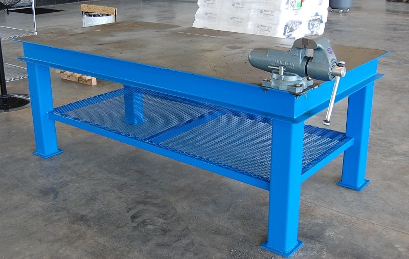
the more I look at this work/shop bench, the more I want something similar, built,in my shop!
and Im sure most of us that have room in the garage could sure use a good solid work bench, OH yeah!
its just a pipe dream at this point ,as my finances won,t currently allow it, but I,d like ideas from you gentlemen, on how to make the legs have at least some minimal adjustment, to compensate for a floor location that might be just a bit less than exactly level,obviously you could just stuff a shim or two under the legs if required, but having to stuff shims if required is really a less than ideal solution, that a well designed bench should be able to cope with.
(as I,m sure most guys realize most poured concrete floors are not always perfectly level, over the entire shop floor surface)
Id also like to have a few pull out drawers , added to the design, to keep welding clamps and supplies in and maybe a slide out rack to hold a few tools.
plus some kind of parts list and cost to build something similar.
and having a well braced top with at least a 3/8" steel top surface seems desirable
obviously theres a great many options available and you might want to build it so its easily disassembled for transport??
having the legs bolt in place would allow you to insert washers as spacers on the bolts to adjust the effective leg length IF IT WAS PROPERLY DESIGNED
Id think basic dimensions should be 4ft x 8 ft so you don,t need to cut a sheet of 3/8" steel plate as the top surface, and leg height , made from 3" square 1/4' thick square tube of about 36"-40" seems about right??
IM sure some of you computer geniuses,who far exceed my meager computer skills , could post a detailed exploded diagram of bench plans with those features shown????? -
Basically, I made my own bellhousing to adapt a Ford Toploader 4spd transmission to my old school SB Chev V8. I can buy one for around $450, but it's a heavy 1/4" thick steel monster, and I prefer building my own lighter parts if i can. I'm not concerned about it not being "SFI certified", as it's just a fun street car and i have no desire to make it legal for the track.
The mock-up began with an old 400 block and an empty transmission case. I am using the alignment bar from my rearend narrowing jig to keep everything straight and true. I spent a couple nights machining some steel pucks to fit in the block's main bearing bores and also the bearing bores in the transmission case. The pucks have an 1.501" hole in the center so that my alignment bar will slide inside everything to keep the engine and transmission bores concentric. I made a ring to center the plate that the transmission will bolt to, and a tube spacer that will set the desired distance between the block and transmission face. I have also made the rear plate that the transmission will bolt to, and have laid out the the flange that will bolt to the block and serve as a pattern for the block plate that will fit behind the flywheel.
I'll snap some pictures in the next day or so. Working in my spare time after hours, I expect it will take me a week or two to get it done. The transmission is getting some special work as well, getting faceplated in 2nd, 3rd, and 4th. I'm adapting an aluminum tailhousing from an SROD overdrive trans to replace the Toploader's stock iron piece to shed some weight. Also machined down the Ford throwout collar so that I can use my existing Chevy hyd throwout bearing.
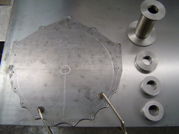
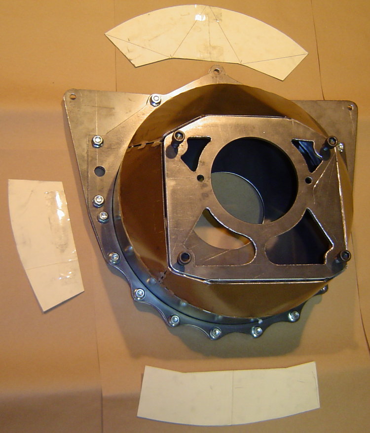
Here's the pattern I made out of 1/4" steel. All the hole locations were laid out, centerpunched, and drilled 3/16" so that the pattern could be transferred to the blank piece of 1/8" that it's laying on, which will be used to make the block protection plate. The steel pucks on the right are the pilot rings and spacer that i mentioned in an earlier post that locate everything in the correct positions for mock-up. Later this pattern will get the bolt holes drilled and the large center hole will be cut out, turning the pattern into the flange for the front of the bell...
Here's the drawing I used to lay out the block bolt pattern...
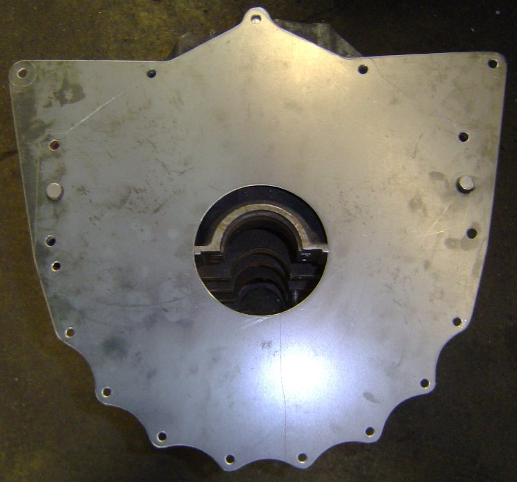
This is the block plate after it was cut out and drilled. The large hole in the center is for the crank's flywheel flange to stick thru, and the 2 larger holes on the sides are for the locating dowels in the block...
This is the pattern after i drilled it out and cut the center out. It is going to be the forward flange of the bellhousing that bolts to the block, the large hole in the center is necessary to clear the flywheel...
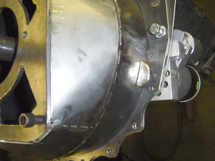
Here's the block plate on a block. The upper "wings" were added as mid-mounting points that will hang the back of the engine at the firewall...
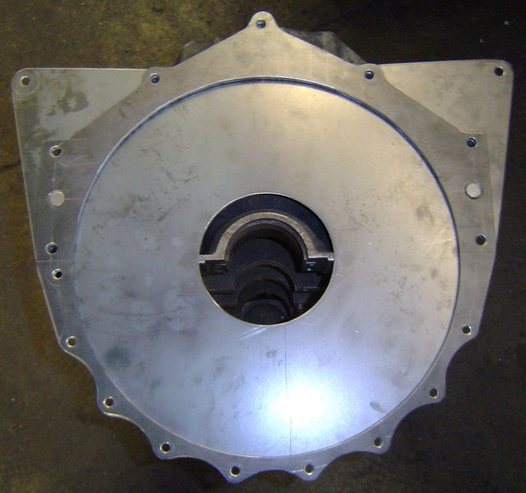
Here's the block plate and flange on a block. The block plate will be sandwiched between the block and bellhousing as shown. I'll soon be creating a hole and pocket for the starter.
Here's a pic of the rolled ring welded to the bellflange. All the holes still fit perfectly...
The mid-mounts incorporated into the block plate allow me to easily remove the bellhousing/clutch/flywheel from the car without needing to support the engine. Greatly simplifies my clutch and transmission maintenance.
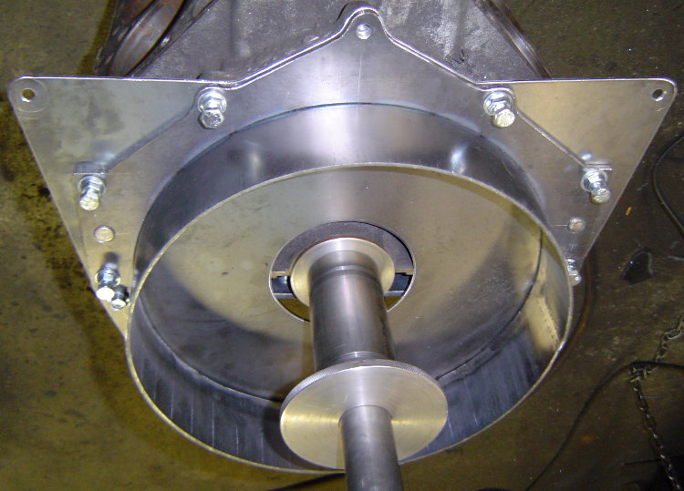
Here's the alignment bar in place in the block, as well as the spacer that sets the depth between the block and trans case...
Here's the trans case in position located by the pilot rings...
I had to take it out of the fixture to make sure i had created enough room to install a SoftLoc clutch, so i figured i'd snap a few pics of the progress.
I started making patterns for closing in the bell by laying out the the top section on posterboard. I quickly realized it was much easier to just cut out slightly larger pieces of posterboard, hold them in place on the bell, and simply apply a little pressure by running my finger around the edges of the steel. This puts a small crease in the posterboard and transfers the exact shape needed, a much quicker way to create a pattern...
The transmission plate is still only tacked in 4 places. After all the rest of the welding is done, i'll put the bell back into the fixture, cut the tacks, and re-position the plate for the best alignment possible before welding it in place. I doubt there will be any need to machine the block or transmission mating surfaces.
Still need to make a pocket for the mini-starter that's going on the car...
Added a cutout for the mini-starter's drive...
Added a starter pocket to the bell as well...
Next is adding a few holes, one for setting the clutch gap and a hole for the hyd t-brg's hose. After that, i'll drill all the bolt holes to finished size, sandblast it, and send it out for powdercoat.
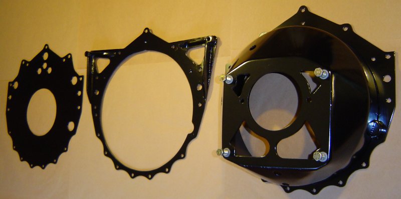
UPDATE-...I went to a 3pc style bellhousing...blockplate, midplate, bell/can. Now i can remove the engine from the car with the flywheel and clutch, and leave the bell and transmission mounted in the car. I can also remove the transmission/bell/clutch/flywheel from the car without supporting the rear of the engine. I also added a couple external "ears" to the block plate, which gives me some easy attachment points for lifting the engine.
The finished bellhousing itself weighs in at 16.3lbs, lighter than a "Quicktime" bell. The entire 3 pc assembly shown below, including the block plate, midplate, and bolts weighs 26.2lbs.
I'll take some pics of the engine lifting fixture i made for it. It plugs into the blockplate's added "ears" and into an "eye" that screws into a hole in the top of the waterpump. It fits over the complete engine with the aircleaner and distributor in place. When using chains, finding a perfect balance point without damageing something can be a challenge. Having a dedicated fixture that plugs in makes the job easy. Been thinking about attaching the radiator to the engine just to make choosing between a couple engines that much easier.
having done some thing rather similar a few years ago , and knowing the time and money it cost to do it, all i can say is this is a job best avoided if possible but still your works darn impressive!
-
So instead of blaming the root causes, being a damaged floor and debris on the floor, you blame the engine stand?
That's like blaming the spoon for making someone fat.
your missing the point here!
NO engine stand design that is safe too use should have a tendency to tip simply because it has a caster wheel roll over a dropped wrench, or hit a floor seam or some other common shop floor hazard, a properly designed engine stand with decent size swivel casters easily takes that type of obstacle in stride, it should remain stable and have no tendency to tip over. its just not that expensive or difficult to select a decent engine stand and go to the minimal effort required to install decent size and quality casters, that make moving the engine stand with the engine mounted far easier and safer and with far less of a tendency to tip even if it does hit some object on the floor.
yes It does take some extra effort , or expense to buy and install the larger casters or select a engine stand design with a wide base that is far more stable to begin with.
yes we all make choices and price is obviously one factor, but saving $100 or so and working with an engine stand thats inherently unstable is in my opinion a poor choice
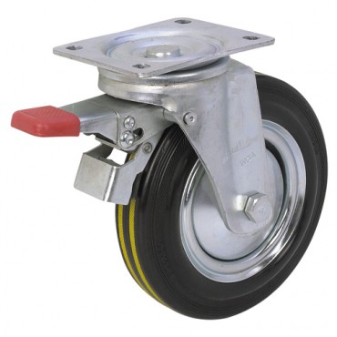
adding these caster wheels to all my engine stands made a huge improvement to the shops engine stands
http://www.harborfreight.com/8-inch-cushion-tire-swivel-caster-with-brake-46819.html
each of us is free to make our own choices , but having an engine fall and potentially injure me is one I can most likely avoid
-
http://forum.grumpysperformance.com/viewtopic.php?f=38&t=10485
look over this link
if you have the desire, a welder , a good deal of fabrication skill and can measure accurately, theres very little in engine swaps that you can,t do.
-
frank sent me an e-mail, note to tell me about a near miss, he had and , as a result its finally starting to sink in, that the cost vs value of those dirt cheap engine stands is hardly worth the cost saved.
http://www.harborfreight.com/1000-lb-engine-stand-69520.html
Frank had purchased an engine stand, like this one ,pictured above, from some auto parts store years ago.
well last night Frank was moving an engine mounted on that stand and one of the cheap swivel casters locked up in small flaw in the garage floor,
the result was the engine fell, and frank without thinking in that instant, tried hard to stop it from falling , and sprained his arm rather badly and barely missed crushing his foot!
every engine crane and engine stand Ive ever seen came with crappy steel wheels about 2.5"-3"in diam.
but you have options (yes these adds $80-$100 to the cost of the engine stand) how much do you save by loosing a toe or breaking a foot keeping the cheap crappy casters
http://www.harborfreight.com/8-inch-cushion-tire-swivel-caster-with-brake-46819.html
http://www.northerntool.com/shop/tools/product_200305217_200305217
a decent engine stand with decent casters is a far safer tool, and yes both the engine stans shown below need better casters added, but at least they are semi safer designs than the upper engine stand shown
http://www.harborfreight.com/2000-lb-foldable-engine-stand-69521-8970.html
BTW YOULL WANT TO MEASURE the engine stand legs and bolt hole spacing in the caster mount plate,AND SHOP CAREFULLY, YOULL WANT TWO OF THESE SQUARE U-BOLTS TO LOCK EACH SWIVEL CASTER TO THE ENGINE STAND
READ THESE
http://forum.grumpysperformance.com/viewtopic.php?f=59&t=8443&p=29605&hilit=engine+stand+grade+eight#p29605
http://forum.grumpysperformance.com/viewtopic.php?f=27&t=3724 -
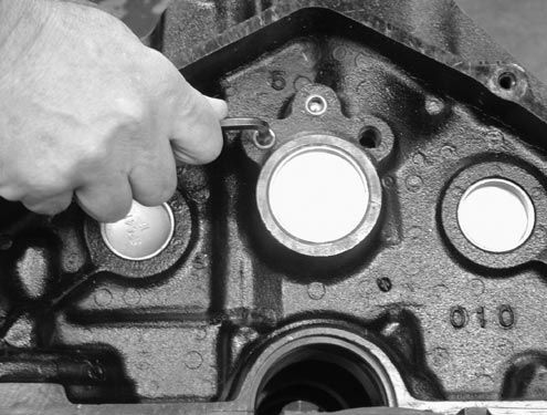
the first step should obviously be to locate the source of the oil leak, Id suggest getting several cans of spray brake cleaner and totally degreasing the area, and then blowing a bit of talc powder over the area so any new oil flow leaves a very obvious track back to its source,
but in the area you mention, rear seals,
the rear intake gasket and the oil pressure sensors
that screw into the block are all suspect as are the rear cam plug and rear lifter gallery oil passage plugs
http://forum.grumpysperformance.com/viewtopic.php?f=55&t=464&p=39647&hilit=rear+seal#p39647
http://forum.grumpysperformance.com/viewtopic.php?f=51&t=1718&p=38740&hilit=rear+seal#p38740
-
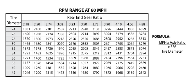
your obviously going to need to consider tire diameter, rear gear ratio and transmission gearing, generally your want the first gear in the transmission multiplied times the rear differential gear ratio to fall in the 10:1-10.5:1 range and cruise at a bit higher rpm that the torque converter stall speed in 1:1 gearing, if you have a over drive gear having a lock-up converter sure helps and a trans fluid cooler is almost mandatory if you have a high stall speed torque converter
you should ideally select a cam , tire diam. converter stall speed and differential gearing that put the engine rpm range in your power curve about 90% of the timehttp://forum.grumpysperformance.com/viewtopic.php?f=71&t=741&p=1048#p1048
-
what youll need is about 40 psi of fuel pressure if your running a stocl LT1 intake ,injectors etc.
heres a stock replacement pump that will supply a stock engine just fine
http://www.summitracing.com/parts/vpn-gca758-2/media/images
MORE INFO
http://forum.grumpysperformance.com/viewtopic.php?f=32&t=33
http://forum.grumpysperformance.com/viewtopic.php?f=55&t=211
-
-
this is fairly common, the first step is trying to determine the source of the oil in the combustion chambers,
obviously the potential sources are
a leaking intake gasket sucking oil from the lifter gallery
worn valve guides and or valve seals
or bad or worn rings
or detonation damage on the pistons
a leak down test will help locate the source.
Id also suggest you post clear pictures of your spark plugs and verify your ignition advance curve."
btw a quick check that will help but not 100% prove or can be used to find out if the rings or valve train is the source of the oil, is have a buddy follow your car and accelerate hard with the throttle wide open,then let the engine slow you down by jumping off the gas, if its rings it tends to smoke more on hard acceleration when theres more cylinder pressure, if it smokes more on DE-acceleration as the engine slows the car its frequently high vacuum sucking oil thru the valve guides[/color]
http://forum.grumpysperformance.com/viewtopic.php?f=87&t=332&p=14272&hilit=leakdown#p14272 -
-
the first thing you want to deal with is LIMITING easy access, to the car, obviously a fenced yard with a securely locked gate, and a locked garage if possiable is a good start.
if you have motion lighting and video cameras it helps, these need not be hugely expensive and if your mechanically inclined setting up an alarm systems not that difficult.
parking a unused car in front of a garage add some difficulty to easy access.
you want to thin thru motion activated lighting and if possiable have video survailance and monitored alarms
next you want some mothion and contact alarms on both the garge and the shop access.
simple things like a pad lock in the garage door frame to prevent it being opened if you intend on being away for a few days or having a trusted relletive stay at your home helps, large dogs , especially ones that are not overly freindly to visitors might be an option. in your fenced yard.
http://forum.grumpysperformance.com/viewtopic.php?f=87&t=3174&p=31717#p31717
http://forum.grumpysperformance.com/viewtopic.php?f=28&t=550&p=691&hilit=security#p691
http://forum.grumpysperformance.com/viewtopic.php?f=27&t=297&p=362&hilit=security#p362
-
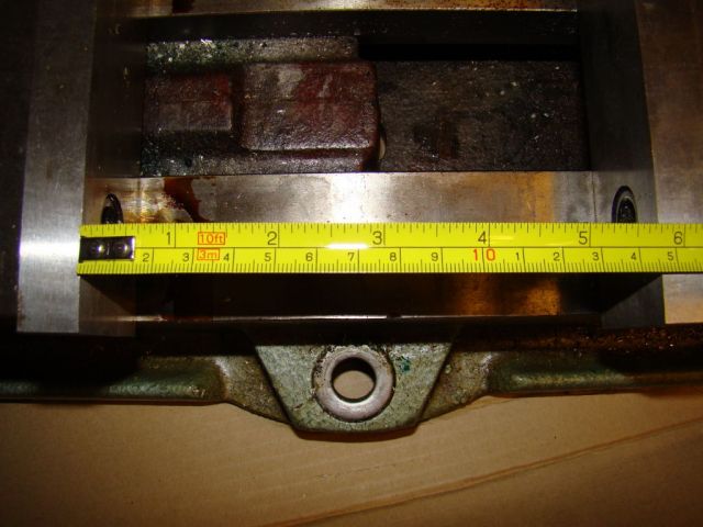
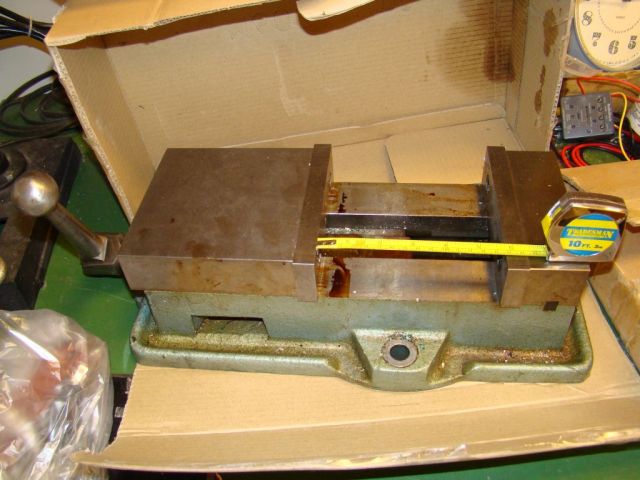
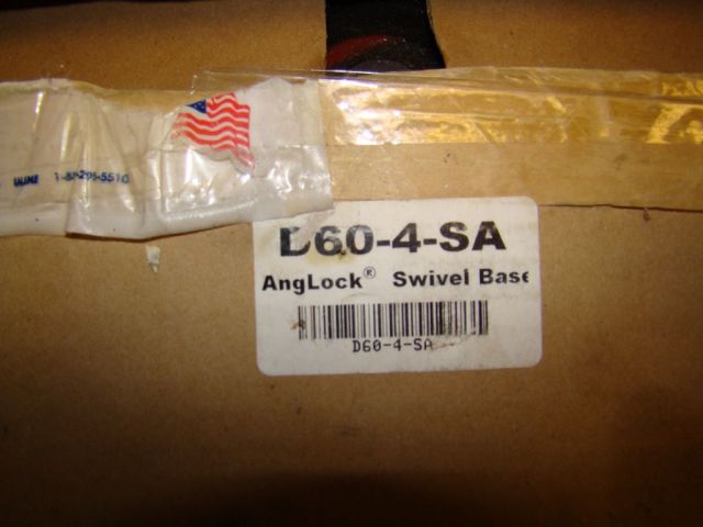
Grumpy, I have a used mill vise with a swivel base that opens to 5.75". The mill it came off of looks very much like the one you pictured. I'll have to ask the guy I got it from the make of his old mill. I'll take some pics of the vice and base for you. I'd take $250 + shipping for both.
I apreciate that offer a great deal, in fact Id jump on thayt if it would work, but like I stated it would need to open 6.5" as thats the minimum size of the material I used to fabricate some custom components
-
having done this a few times , If it was my car Id suggest the 200r4 option, those guys with the turbo buicks have long ago worked out the bugs in the trans and properly built it easily handles 600 hp
http://www.transdepot.net/2004R-_c_10.html
http://www.transmissioncenter.net/200-4R.htm
the 4l80e is potentially stronger but much heavier larger and requires conversion to full manual control or a rather expensive electronic control harness and controler
-
Ive been in similar situations in the past. I've also confirmed the old adage is true: Buy cheap, buy twice!
The quality on the unit you posted looks good from the picture. The only way I see getting the intentionality you get with the unit you posted is to buy cheaper, but in my experience the cheaper tools require dis-assembly, cleaning and proper lube upon purchase, and even then they never work as well.
Put a price on your time and frustration, especially knowing that quality tools do not lose value like cheap tools.
while I totally agree ,that cheap tools are rarely a bargain, in the long term, and think about the true cost of cheap tools the 6" version of that vise is close to $760, I just wish I had a job I could depend on, that made me enought to make expenses and allowed a bit of cash flow for tools


remote oil filter help needed
in Gen I & II Chevy V8 Tech Board
Posted · Edited by grumpyvette
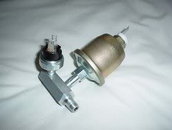
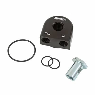
Zinpieces thanks for posting the clear pictures of the oil filter relocation.
Its always rather amazing to me when I find guys who have for decades been forced to temporarily remove sone component like the headers to allow access to remove an oil filter during and oil change when theres been the readily available option to mount a remote mount single or dual oil filter in a far easier ro access location, and the obvious option of adding an oil cooler or dual flow oil cooler and transmission fluid cooler.
a little careful meassuring and thinking things through, and some careful shopping for adapters will generally allow you to relocate the oil filter and use a significantly longer and/or larger oil filter than could originally be installed, thus reducing the restriction to oil flow by significantly increasing the area of the filter medium surface,and adding a couple magnets to the instalation will generally help trap metalic debris
http://garage.grumpysperformance.com/index.php?threads/oil-system-mods-that-help.2187/
SmCo Samarium Cobalt Disc Magnets
http://www.magnet4less.com/
http://www.magnet4less.com/product_info.php?cPath=3_27&products_id=254
http://garage.grumpysperformance.com/index.php?threads/whats-a-windage-tray-do.64/
http://garage.grumpysperformance.com/index.php?threads/oil-system-mods-that-help.2187/
High Temp Samarium SmCo Cobalt Magnet Discs
572°F Maximum Operating Temperature