

Six_Shooter
-
Posts
1471 -
Joined
-
Last visited
-
Days Won
2
Content Type
Profiles
Forums
Blogs
Events
Gallery
Downloads
Store
Posts posted by Six_Shooter
-
-
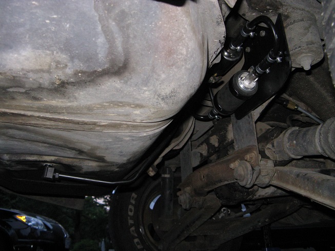
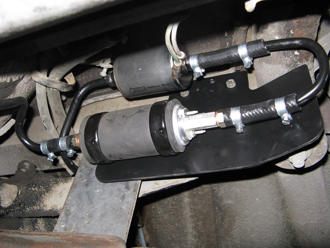
I did mine this way:

It's a little different now since I changed to a different filter, that has a threaded fitting on the inlet end as well, so the radiused tube between the pump and filter is tighter.
-
Sounds like I'd find a different engine builder...
Anyway. As long as the hub is bottomed out on the oil pump drive (or the oil slinger between), then it has enough engagement. I'm sure Nissan would have made the crank snout longer if this was an issue.
Moving the hub back is going to cause other issues, with pulley alignment for the water pump and alternator.
It's been a while since I had my crank snout exposed, but it was around 1/4" or so of distance between the end of the crank snout and the face of the hub, where the washer sits against.
-
So what's the advantage of using this crank pulley/damper/engine combo?
-
I believe the fender liners started in '74. Every '73 and previous I have looked at, in stock-ish form, including my own '73 did not have fender liners nor holes to mount them. I bought a '74 parts car that had them and they appeared to be stock, since there were a couple welded on brackets to hold the ends of them. They are different than the later fender liners in that they only sit inside the fender and do not clip to the fender wheel well lip. A friend of mine had the later ones on his '71 and replaced them with the ones from my '74 because of the lack of wheel well lip clips. IIRC the holes for mounting were in slightly different positions too.
-
There was a thread on auszcar.com that delved into this. As I remember the 2 seater spoiler did not fit the 2+2 very well.
-
I'd be narrowing the rear end, or getting different wheels before adding flares. That just looks too good.
-
The '73 dash does not have the indent next to the hazard switch, since it's is a pull type and not a lever.
Although I am not interested in purchasing a fibreglass or carbon fibre dash (I have a perfect '72 dash to replace my terrible '73 dash), at this time. I would however prefer it to have a '73 style to it, as I mentioned lack of indent next to the hazard switch. However, I think it was only '73 with this missing and earlier dashes all AFAIK had the lever type hazard switch so it might be more common for people to want that. Also being fibreglass would make it easy to fill in. I would also prefer to have the glove box and heater panel areas shaped like the stock dash to allow for use of a stock or matching replacement door and heater control panels. Using flat dashes/panels where the opening were cut out, requires a lot of work for the end user/fabricator to make fit and work right. I don't think anyone with a race car would be opposed to this either, though I'm sure there are a few that would like them to be just flat. IIRC there is already a flat/no opening 240Z dash available isn't there?
I think the '72 '73 layout, where the cigarette lighter was dash mounted would be most desirable than the earlier layout. Even if it's being retrofitted to an earlier car with the cigarette lighter in the console, this would add an extra power port spot and since it seems most people have more than one device plugged into a power port at a time any more, people may really like this. That spot could be used for other things as well, like shift lights, or auxillary switches, or..?
As far as console goes, that's kinda tough, because the two different styles were quite different, though, I would have to think that the later '72/'73 style would be easier to sell, because they were plastic and tend to be frequently cracked. I know I have looked at several to replace my original that was not only cracked but broken in two. I was graced with the gift of a good condition replacement from a good friend so this is not really a concern anymore, but if the price was right, it would be a good item to have and maybe even use as a base to modify, instead of modifying my original piece. Again here having the proper indents and opening for the fuse panel cover would be desirable, along with at least an indication of where the shifter and ashtray are supposed to be. I would prefer if the shifter hole was at least rounded over like the stock piece, but I'm sure others might prefer it to just be flat.
From what I have seen the earlier consoles were a fibreglass/composite already and tend to be in good shape. I see far less of these cracked or damaged than I do the later ones. -
Looks good.
-
I had thought about getting an inside 3rd brake light, but since I couldn't find one that I liked, that wouldn't block even a little bit of the view through my mirror and I had this one, I decided to forge ahead with it. I even looked at making a bracket and shield to mount this one inside but couldn't come up with anything I liked. Once I mounted this on the outside I thought it was a great decision.
-
Since there has been a couple people ask about my 3rd brake light in another thread I thought I'd start a new thread to not hijack the other.
I feel that a 3rd brake is pretty much a must in today's driving world. I know before I installed the 3rd brake light there were more than a few close calls in getting rear ended. Ever since I installed it, I have only noticed one person that didn't seem to be paying attention and get close in a panic kind of way. Yes I do pay attention to what is going on behind me when I am stopped, I also leave space between myself and the car in front of me in case I need to roll forward, again this has also helped in saving the rear end of a few of my cars, you know defensive driving and all of that.
Anyway, onto the meat and potatoes of this thread.
I started with a Safari/Astro van 3rd brake light. Jimmy/Blazer should also be the same. Years seem to be 1995 to about 2003.
This particular light seems to fit the space above the hatch window perfectly as you will see later in this thread. Alternatively you could install this near the rear edge of the roof, which will make wiring much easier.
Sorry I don't have any pictures of the install and did it a few years ago.
I started by measuring out to place the light in the center, and marking mounting hole and wire pass through locations.
I then drilled the three holes, two for the screws and one for the wires.
I then moved to the inside where I drilled a hole to pass the wire into the interior, but there was a problem, there was a re-enforcement plate between the two holes. So since I was at the point of no return, I decided to forge on and drill a hole through this plate from the outside. Then through some creative use of wire, string and pick tools passed a fish wire through from the outside of the hatch to the inside. I had to remove the connector that is on the 3rd brake light in order to pass the wires through. I also had to add some extra tape around the wire where it passes through the inside re-enforcement plate to act like a grommet. I tried to get it so that the wire was actually secure and not able to move around to reduce the chance of chafing. The other holes can use a grommet.
After that it's just a matter of running a wire to the brake switch. Something to note here is that on my '73 with the 3rd brake light attached to the brake switch the 3rd brake light will also flash with the hazzards (4 ways) on, which is something that I wanted so this was a bonus for me. If you want it to work more conventionally, where the hazzards will not turn on the 3rd brake lights you will have to add a diode to remove the feedback from the hazard switch.
I think the next time I do this I will try to pass the wire all the way along the panels that surround the window of the hatch and use contact switches at the turtle deck, or some other way, that I haven't thought of yet.
Onto the pictures, because everyone likes pictures.
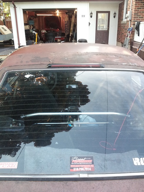
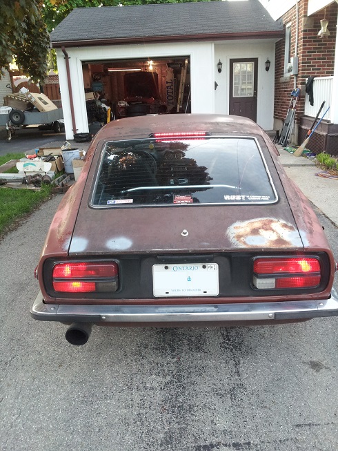
Fits that space like it was meant to be:
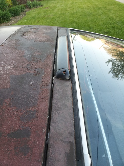
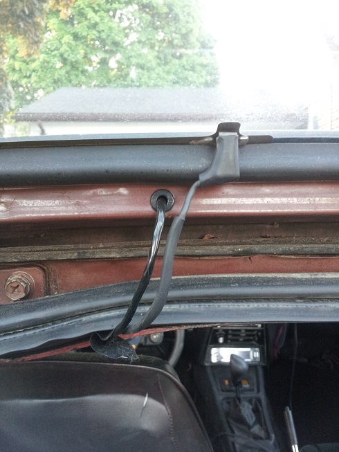
Wire as it passes to the interior:
Lit up:
-
If you rebuild, do yourself a favour, grab a 4 speed and use the shift forks from it. They are cast iron, unlike the 5 speed that uses aluminum shift forks, at least mine did and any information that I have found about the 5 speed also suggests they all do. I don't recall the designations, but the later 4 speed that is the almost twin to the 5 speed is the one to use.
You do need to drill out the roll pin hole in the shift forks to the proper size due to needing to use the 4 speed roll pin, which is larger. It's an easy modification though.I lost 1/2 because the part of the shift fork that wraps around the outside of the shift shaft, had broken away. It had been that way for a long time, I just didn't realize what the problem was because I had been able to drive the car, just getting into 1st was sometimes not easy and it would pop out of 2nd. One day I really yanked for 2nd and lost those two gears and when I pulled it apart, that's what I discovered.
-
I think any year of Safari van has this 3rd brake light, along with several other models of GM vehicles.
Running the wire was interesting. I drilled down through the outer skin under the light and through the inner skin towards the rear of the car. The issue was that there is a re-enforcement in between the two holes I drilled, so I had to drill another hole and fish the wires through. I don't like how there's the metal divider with just a hole drilled in it and no grommet. I wrapped extra tape around the wires for this point where it passed through, to act like a grommet, there was enough that the tape held the wire in place when pushed into the hole. It wasn't a preferred way to do it, but at the time I had already drilled the other holes and didn't have much of a choice.
I think the next time I do it, I will try to run the wires down to the bottom of the hatch and put contact pins in the deck near the latch.
You might want to consider placing it on the roof, but I didn't like how that was going to look overall, and this light fit that space between the widow trim and the top edge of the hatch perfectly. -
I'm quite sure the early 260Z would use the 280Z hatch trims, because if I'm not mistaken it has the raised strut mount points, which is one of the major differences between 240Z and 280Z hatch plastics.
-
Power antenna switch. The original antenna was a power manual type.
-
I installed a 3rd brake light from a Safari van on my hatch. I know it's saved my ass end a couple of times now.
The Z31 trim is too wide for the S30 (I have or at least had one to try).
-
I'm not using MS, but I am running a non wrapped turbo and downpipe, and have done so for 5+ years.
The only hot start issue I encounter is after the car is fully warmed up and I stop for between 5 and 10 minutes. Heat soak of the fuel rail causes a very lean condition, but the engine ALWAYS starts at hot start. I have also had reported coolant temps of over 230*, but this was most likely an air pocket because this only happens when the coolant is a bit low, but there was no stalling. I have seen hot restart coolant temps of over 220* (with topped up coolant) from the coolant baking after hot shut down, still the car started. My intake temps are usually around 160* F at this point (MAT sensor in place of the cold start injector).
Because of this and other people's experiences with hot start I would say that this si something in your tune, that is causing the stalling at 165-ish and hot restart issues.
What are your reported injector pulse widths when this happens? What is the actual cranking AFR? -
There's still mechanical advance that needs to be locked out.
Or you could just unplug the vacuum advance....
-
I haven't used a dizzy on my car in 5 years, so I don't recall when the changes were, you are thinking right.
Yes, the purple and green wires on the MSD box are what I'm referring to. As said the MSD instructions can be found on the inartweebz, more specifically on the MSD ignition website.I also ran the GM HEI ignition module before I went DIS, only really because I had computer controlled timing and it was the best way to give the ECM I am using the DRP (Distributer Reference Pulse) that it needs. The GM HEI module swapis pretty simple, but unnecessary in your set-up from what I read, the MSD 6AL can do what the GM HEI module will do for you. In your case you would use a 4 wire module, that is literally the 2 wires from the dizzy's reluctor, an ignition source and a trigger to the coil.
-
Ignitor - the little black box on the side of later dizzys, or sometimes a separate box altogether that the reluctor wires attach to, to trigger the coil. It sounds like this is what you're using to trigger the MSD through the white "points" trigger wire.
You can bypass this and connect the red and green wires to the magnetic input of the MSD 6AL box, you will have to determine the polarity of the Nissan reluctor though, for it to work correctly. They will usually work ok if connected backwards but work best when the polarity is correct.
I haven't personally used a MegaJolt, but I believe it will work with either dizzy or crank trigger. Read up on it to verify.
-
So what actually failed? Did the outer portion of the hub (where the wheels sits against) break off the bearing section? Or was it something else?
Some pictures of the failed part(s) might help determine what happened and possible ways to keep it from happening again.
At first I didn't know what you meant by hub failure, until I saw the wheel passing you on the left, I had to watch it again, to see when it failed. I'm not trying to be disrespectful, but that is pretty funny to watch. To have your wheel come up past you, especially on the opposite side of where it came from.
Was there much other damage? It looks like the fender took a hit, how is the bottom of the strut/suspension? It didn't sound like it scraped for long, so I would hope that it should be ok that way.
At 59 seconds into the video is that a bump in the track or that when the hub actually failed? It looks like the car gets jolted around at that point.
-
As said you simply want to keep the centrifugal advance from being able to do its job, so once you remove the plate under the dizzy cap that the vac advance attaches to, it should become pretty clear what you have to weld up. I prefer welding to other techniques.
-
It sounds like you're still using the original ignitor to trigger the MSD box? In your situation I would try removing that box and using the magnetic pick up of the MSD directly from the ignitor.
The only reason I ever use the stock ignitor/ignition modules is when there is computer controlled spark, which you will not have.
Why are you using the MSD box and not just triggering the coil directly from the ignitor? Actually that's another test you can try, bypassing the MSD box.
If you find that the MSD box is an issue and you don't want to use another MSD, take a look at the MegaJolt. It's more than just an ignition amplifier, you can set different timing curves and even go DIS with it.
-
Yes, it will fit.
-
That's an interesting front diff mount.
Try it out, but I agree that I think you'll find that at least on some cars the captured nuts will break loose. If need be, I would look at making a mount that is based off the crossmember, where the stock diff mounts at the front, then create a snubber or limiter strap to reduce the pinion angle change during accel. I know the problem with this is that the 8.8 diff is much shorter than the long nose R200, and so you get some leverage happening using stock mounting points. This is something I am trying to work out in my own set-up.


Hidden antenna? Need help and options.
in Interior
Posted · Edited by Six_Shooter
I have tried many different electronic antennas, in many cars and all have less then stellar results. Some only seem to pick up radio with the car engine off. :facepalm:
I'm sorta tempted to use an external electronic antenna, mounted at the rear of the roof, but the best "antenna" so far has been a length of coax plugged into the radio to extend it to the rear of the car over the trans tunnel (temporary install) and a wire then clipped to the center conductor. I was trying to use the rear defroster grid as an antenna, but it didn't work out so well.
I'm really tempted to open the original antenna hole up (I also welded mine shut) and just install an automatic antenna.