

ol doc gully
-
Posts
76 -
Joined
-
Last visited
Content Type
Profiles
Forums
Blogs
Events
Gallery
Downloads
Store
Posts posted by ol doc gully
-
-
5 hours ago, Neverdone said:
Wouldn't it be much easier to spend 90 dollars on a bead rolling tool (i.e. https://www.eastwood.com/eastwood-elite-8-heavy-duty-bead-roller.html) and then just remake the whole thing and weld that in?
Cutting out the whole thing adds a lot of complication (up high on the other side of the firewall, etc), this is not a bare chassis restoration. However, that is a much better deal on a bead roller than I would have expected, may be worth getting regardless...
21 minutes ago, grannyknot said:Or, since it is all hidden behind the battery anyway, flatten the bottom edge of the stamped section where you made the cut and just weld it up to your new patch.
I'm curious if the panel will start to bow or anything by increasing the width but I think that is workable, I may go this way.
Thank you both for your input.
-
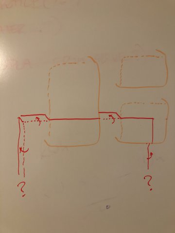
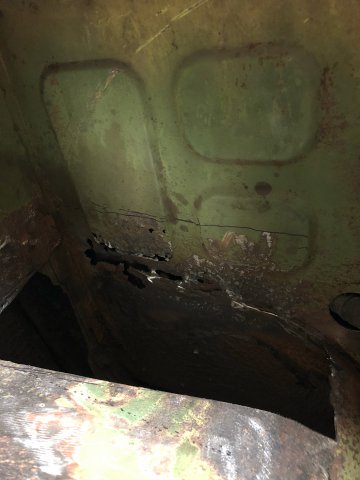
I am repairing rust under battery tray. Going to do the firewall piece first but can't figure out what the best way is to get a piece to match with the stamped / bead roll shape?
If you look at the picture of the area you can see the line of approx where I need to cut to replace rusted bits (approx, will keep grinding to confirm). I definitely do not want or need to cut up high enough to be above all of the stamped shapes, so regardless of exactly where I cut I need to figure out how to fit these shapes.
The drawing is my best stab at how I might go about fitting a piece to match those shapes; basically leave some tabs that I can bend over and weld to the recessed portion. But its not going to look very good because in multiple areas (ie, sides and bottom) it will have to line back up with the recessed part of the firewall. Or I could try to hammer those areas flat where they meet the panel I am welding in, but that seems even less desirable.
What has anybody else done??
EDIT: Thinking about it more now after re-reading this posting; strength-wise, I think having something that is completely in plane with the recessed portions is likely the preferred solution....
EDIT EDIT: I suppose I could do the reverse of what I have drawn; weld to the recessed panel and leave tabs to be bent back *out* to fill in gaps at bottom of the stamped shapes. But that seems... difficult

-
I'll take the COOLANT CROSSOVER TUBE if it is what I think it is - sent you a PM.
Thanks.
-
I would think it’d be really tough to be that precise, with such small offsets, enough that may be worth it to just use two flanges and some straight pipe, maybe with a lil pie cutting?
-
On 5/10/2017 at 11:48 PM, seattlejester said:
Not sure what you mean by only option. 225 will go on a 7 inch, a 225 on a 9 is going to be quite a stretch. You might consider looking at something with a taller sidewall to compensate to keep the wheel/tire diameter in a realistic range if stretch is your game. 225/60/15's have quite a bit of choice for example, or if tire width is desired you can do other sizes like 245/40/15. You just have to step down to miata/E30 diameter. In the 24 inch category there just isn't too many choices.
Would you mind posting some examples? 225/60-15 is (to me) the perfect size tire for the Z, but all I can find are crappy all-seasons (or hoosier bias ply), just want to make sure I’m not missing anything. 235/50 R888R is a bit of a compromise bit that is a wiiiiiiiiiiiide tire. 225/50 R888R is my leading choice now.
-
sounds good, will be interested to see it come together. The good thing about the ZX12R throttles is they have the same spacing as the DCOEs (90mm) so I’ll just have to space out each pair; there’s definitely trade offs with any of em though.
-
stumbled across your other thread, im actually slowly putting together a setup with ZX12R ITBs. have the manifold and one set of ITBs, going to start the spacing and mounting shortly and order the second set, no rush though as I am overseas and my car is in a barn so its just a fun basement tinker project. have any pics of the triumph ITBs you are using?
one thing i havent seen you discuss, with regard to fuel setup, is that youll want some baffling or, as i'm doing, a surge tank (or fuel cell)
-
pretty great walkthrough for compressor size calculations from Garrett:
https://www.turbobygarrett.com/turbobygarrett/choosing_turbo
-
ive been surprised at how much abuse mine has taken but thats incredible. how long might it have been running without coolant? it was completely empty?
its also the main reason i will stick with the L series - worry free vintage lapping.
-
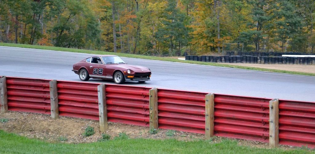
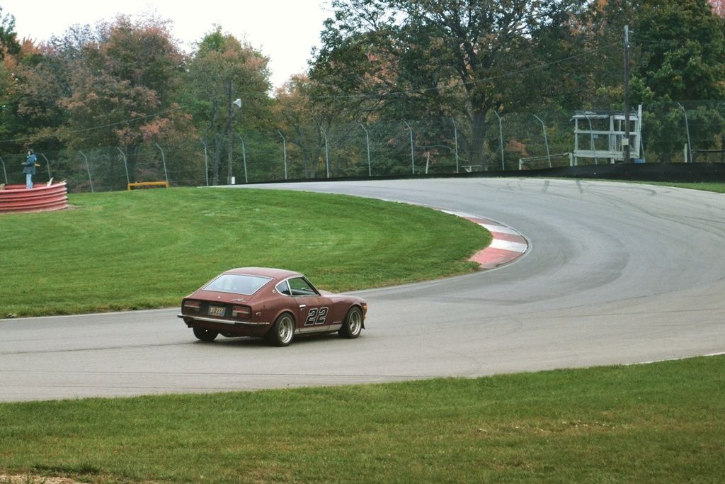
been a while but came across some more pics from mid-ohio i realized i never posted on here

-
Short and large diameter runner are for HP and small, long runners for torque I believe. These are long and large runners, so best of both worlds?
Still, the flange doesn't fit the head.....
What If you cut it off behind the flange and weld a EFI flange on it with the injector bosses and port it to match the diesel runners, would this be a good low down torque manifold?
I'm asking because I have a L28 in my heavy Nissan Patrol which could use more low down torque. I'm going turbo with it and want as much torque as possible (already have a P90 head, RB20 turbocharger, flat top pistons)
the main/easy correlation is with length - short runners for high rpm performance, long runners for low rpm performance. this has to do with benefits from tuning for pressure waves as much as actual flow. diameter has to do with velocity and so is more of a dependent variable based on other design factors.
i like the idea of this manifold for a mild/street turbo application though. long runners for good low rpm response and boost for high rpm. i think the runners are still a bit long for that though, so i think you're idea of welding a plenum to the lower section is great.
but whats teh point of any of this if the flange doesnt fit?
^ I was just thinking along the same lines as JP.
1: First the current injector position has to go. It is just wrong . You can buy weld on universal injector bungs and easily position the injectors in the right position on the manifold. Factory EFI designs and angles are a good starting point. You want the spray pattern to hit the backside of the intake valve . Right in the center of the valve is a good starting point.
2: Cut the " J " turn out of the manifold. Leave as much of a straight leg as you can on the flange side and the plenum side. Then weld the two sections together. Basically you should now have shorter runners with a larger diameter ( than the Factory NA EFI runners ) that allows a straight shot into the cylinder head. Win Win. Of couirse Plenum is now rotated 90 degrees, so you may have to reposition the TB flange, if it not a symmetrical square flange.
With these modifications, particularly the injector boss re-location, you will have something interesting to test that will at least work.
Look around the internet and you will find successful and proven high performance Plenum manifold designs that all have similar characteristics. Key points are:
A: Injector placement as close to intake valve as possible.
B: Proper plenum design. This can be very tricky, especially on Turbo engines. What looks right can be terrible from an actual distribution of air flow. There are some basics to follow, but using a pre-made factory or Custom plenum is a not a bad idea. Unless you have $100,000 or so of CFD computers and air flow testing equipment sitting in your basement
C: Runners as straight as possible. No unnecessary bends to slow down airflow. Velocity is important even in a dry manifold. Some gentle bends may be seen in some of these manifolds, but that is only to facilitate port entry angle and hood clearance.
Here are some pictures picture of proven designs for Audi/VW 1.8 5 Turbo engines. NA version is virtually identical. A good design for a NA engine will also be good for a Turbo engine, and vica versa.
SEM manifold:
034 Motorsports manifold
i agree but a few pesky clarifications
aftermarket manifolds are entirely built for high boost/high rpm - thats why they look like they do. doesnt mean they should be used as a guide for intake manifold design and doesnt mean they are right for everyone. for instance, factory RB manifolds look a lot like the diesel manifold being criticised here (pictures below)also i entirely agree that the injector placement in the proposed manifold is... far from ideal. seems to be a convenience factor based on where the original flange was. but FYI the common practice of injector placement at the head is actually primarily to help with emissions (esp cold start) but the goal is just getting a well homogenized/atomized mixture in the chamber and there are other alternatives.
-
i know this is an old thread but as a person looking into these kinds of setups i havent found a more concentrated source of useful information so i think it deserves a bump
i've been specifically researching the holley terminator EFI to replace the holley 390 on my clifford for a turbo setup -- SuperDan, did you ever go turbo? very glad to hear the terminator CFM isnt too high, was worried about the same. i also definitley would not have thought of the heat shield being so necessary.
anybody else using any of these 4bbl TBI setups in a turbo application? also curious how well the Holley HP software can be setup to deal with boost - will be my first time tuning an engine but that kind of work is close to my profession so im excited to learn
also as was said earlier im tempted by the potentially short/direct path from turbo to intake.. although i have low boost aspirations im still hesitant to try it without an intercooler (even though blow through guys do it all the time).. any thoughts on air-to-water intercooler setups?
-
Haha OK.. let me know if you don't end up using it.
-
hmm PM me how much... i come to Rochester often for work but thats still not too close to you so we'd probably have to ship
-
How much is left on the table with a square port header on round port head? It's the setup I've always had since its how my car came, but just wondering how motivated I should be to replace it. Seems like it would be leaving a lot on the table, so just curious if anybody has switched between the two.
(Sorry, i know its an old thread, but is the main one that keeps coming up through search and most relevant so figured I'd ask here.)
-
you should get some glamour shots on the stand with both the fuel line block and the head assembled - i bet they would make facebook rounds quite quickly and get you some more interested parties ...as well as dress up my work laptop desktop
-
man... the fuel lines and ITBs really brought this thing to life. love the motivation, care and crafstsmanship. thanks for letting us peak in, its a pleasure to be following.
-
Hahaha indeed - "there's over 1,000 hp in this photo!"
-
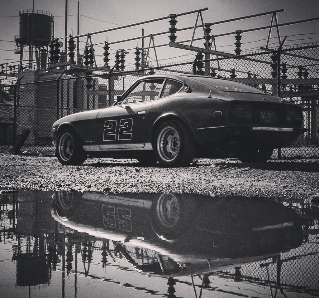
got into one of the last track days at Mid Ohio - great success, car ran flawlessly
then just this past weekend finally made it out for a cruise in Hocking Hills, and got some good pictures in before winter hibernation. AWESOME roads out there, will be going back a lot in 2016
-
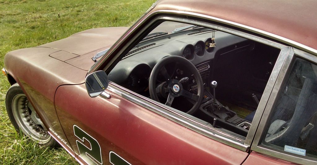
Yeah I'm not too keen on a buzzer but I am going to toy with different light placements - I'm kind of thinking if I place one near the windshield defrost vent it may work as a makeshift heads up display... as long as its bright enough... Otherwise the clam shell is at least the least worrisome part to drill into so i may just put a more subtle light there.
-
Well, it looks like i'm already on the path set forward by dirt cheap chinese manufacturing, but I do appreciate that input; especially since I'd likely be going that route if/when the ebay piece breaks.
-
Yeah I never had any problems switching to electronic dizzy but have definitely heard of others'.
Ordered the dirt cheap shift light so I'll let y'all know 'how' crappy it is ..eventually, apparently it's coming over from China via canoe. -
I am just trying my darndest to keep the dash OEM looking with only subtle hints of race car-ness, so would definitly like to keep the OEM gauge; but youre right, that doesnt look out of place at all.
Was trying to find some useful reviews of those dirt cheap shift lights ($12 ones that pop up as "1000-11000 RPM adjustable aluminum shift light") This guy appears to have done pretty much exactly what im talking about as far as taking it apart and using a separate light bulb, and did it with the same light im talking about so i may just try it... http://www.dsmtuners.com/threads/small-shift-light.338723/#post-151888744
-
Oh wow... I had looked all over Jegs and Summit and Amazon and not seen anything for less than $50 (and most of those required separate sending units). The tach+shift lights are on ebay for $40, and separate shift lights are on there for only $12. What a world we live in. Hope it lasts...I was actually hoping for a bit more 'subtle' installed look but this is still certainly the way to go, maybe I'll tear it apart and just mount the light somewhere. Thanks Jester.


Chickenman Remote Tune Service Review
in MegaSquirt
Posted
Would love to enlist this help. I sent him a PM on here, but not sure he comes around often. Does anyone have an email they think would be OK to use to make contact?