JMortensen
-
Posts
13727 -
Joined
-
Last visited
-
Days Won
61
Content Type
Profiles
Forums
Blogs
Events
Gallery
Downloads
Store
Everything posted by JMortensen
-
On another front, I went out to my shop yesterday to look paneling the bottom some more. Grabbed my magnetic 4' level and slapped it on the bottom of the fuel cell that I had mounted at a 7* angle many years ago, in preparation for making a diffuser. Thought for sure the diff cover would be in the way. Nope. It cleared by 1/8" or so. When I get the cooler on I'm going to run the standard cover, so more clearance at that point. So then I held a piece of angle up to the frame rail and figured out where it intersected the level. From that intersection to the back of the car I've got about 42". So I can make a 3.5 foot long diffuser and it will fit under the car, and the height of the diffuser in the back works out to about 6" tall. Also, the control arms are high enough with sectioned struts, camber plates, and droop limiters that I think I can make the diffuser full width between the tires and not hit anything. I had thought that the diff cover would be in the way and that I'd have to make a shorter steeper diffuser, but nope. Can go fairly huge. So now I've got all of those plans going in my head. Thinking I'll do AL and figure out the sizes with less hassle and expense, and then maybe redo in FG or CF later on down the road. I run the car with a bit of rake so I might have to have the outer fences extend lower than the center to keep it close enough to the ground to be effective, but I did crack open Competition Car Aero and they showed that a 10* diffuser was best on a similar height 350Z, and that it worked even better on a raked chassis (basically the rake doesn't affect the flow attachment, so raking the chassis improves the effective angle of the exhaust of the diffuser). That's good stuff. So might try to build at 10* and just fit it where it fits. I don't think the diffuser entry will be that much further back with the extra 3* of angle. EDIT--Looks like the difference in length between a 7 degree diffuser and a 10 is .259".

-
Looks like "shaft adapter" is the term that gets you what you need. 5/16 to 5/8 is not a common size, but 8mm to 16mm is and 5/8 to 5/8 is. Found 2 solutions: put a sleeve over the 5/16" shaft that is 5/8" and then run a straight adapter, or run the 8mm to 16mm. The problem is that there is a flat on the 5/16 and a key on the 5/8 shaft. I suppose I could just get the 5/8 to 5/8, drill a hole in the 5/16 to 5/8 bushing and then use a set screw on the 5/16 side. That should work... Thinking I'll buy the same type of motor Big Al did, along with a bushing and an shaft adapter and see how nice the pieces go together. Should be pretty simple in theory. Theory doesn't always translate to practice though. EDIT--Found a premade adapter for $16. https://www.ebay.com/itm/292457042171 EDIT 2--Bought the motor. Will verify shaft diameters then order the adapter. This is great. Don't have to spend another $200 or try to get rid of the part that I already purchased, and I'm sure the motor will hold up as it's what they use for the other style pump, gets rid of the diaphragm. Thanks Clark, you saved the day.
-
Nice to see I'm not the only one who has been down EXACTLY this road before. Thanks Clark. This first one looks promising: Found a ShurFlo pump on ebay for $29.95. I've got $100 into the single stage pump. Would be awesome to tie together and get out of it for less than the Tilton cost and not have to worry about diaphragm. I don't know what the adapter to connect the two together is, but seems like should be a common size adapter, going from 5/16 to 5/8. Tried "split collar adapter" and no joy. All of the people saying "Tilton works fine" is also making me question the utility of all of this...
-
Just did a quick search and the polypropylene that the $80 pump is made from softens at 140 - 150* C which is 284-302* F. Man I am tempted...
-
If I still had the car torn apart I'd probably hack it up for the pulley setup. To retrofit would mean quite a bit of disassembly to clear up space, then major hacking, then trying to box it back in. Just not worth it. The idea of getting a good quality electric motor and running a pulley and then mounting the motor and pump next to each other isn't that crazy, but just adds enough complexity that an electric pump seems like the easy button.
-
Looks like RV water pumps are VERY similar. Diaphragm pumps, most seem to have Viton seals. Looks like the lower model Tilton equates to ~$100ish pumps like this one: https://www.ebay.com/itm/184876097420 Here's a slightly upgraded one 10A, 3 GPM, 60 psi, but with 1/2 NPT fittings for about $80: https://www.ebay.com/itm/263473361911 Tempted to try the last one there. Main thing that had me spooked was the plastic pressurized housing, but looking at your pic the Tilton looks plastic too. Was also wondering if it might be better to go bigger on the fittings to reduce restriction and thereby pressure. Just a thought. Bought cooler with -8AN fittings, but it's a Setrab so can change them out. maybe -10 or -12. I have a bunch of -10 from fitting my Accusump and oil cooler.
-
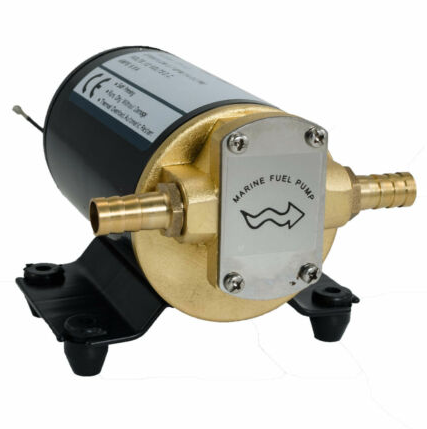
Almost sounded like Clark had found a similar pump with a different name, but cheaper. Britain said that the diaphragm was the weak part of the Tilton. Maybe a gear driven unit would be better. That's what the mechanical one was, and there are these marine fuel pumps which are being advertised as turbo scavenge and diff cooler pumps: https://www.ebay.com/itm/280782665954
-
bjhines was running CLSD when he measured 350* with the cooler. He picked a pretty tiny one though. I think the solution is to size it up until it's big enough. I'd say you hit the mark, so I'll start where you are at and that will probably work for me. What do you mean by #6, Tilton is just a standard pump with viton seals? Not sure what a "standard pump" is.
-
Got the pump. Took it out to the shop. Went and looked under the car. My mental image of what was under there was so wrong that now I can't even remember how I thought this would all go together. It is a DEFINITE no go without major trans tunnel hackage and putting the pump inside the car, and I don't want to do that just because of the fire hazard. I'm just stunned at the fact that I thought I could make it work. NO WAY was it going to go on the right side of the pinion, especially with my drivetrain offset to the right. The reality of what is under there is so much different than I thought. It's not like I haven't been under that car for thousands of hours. LOL I guess it has been a little while, but DAMN! 😂 Now I'm trying to figure out if I can use this pump at all. I remember Gian Bowles at one point had an electric motor bolted to the front of his engine that drove a Gilmer belt, and that ran the mechanical water pump. Maybe I could do a small electric motor driving a belt to the oil pump. Or maybe I should just buy a Tilton pump and make my life easier. The other thing that isn't working to plan is the finned LSD cover has spots where you can install fittings for a cooler. Unfortunately they're just barely under my rear toe adjuster, so if I drilled out the spots the fittings would hit the adjuster. I think I could get around that one by putting a stock cover in and drilling it and installing a fitting through the cover, or by drilling out the drain plug like bjhines did. Ugh. This project just got a whole lot harder...
-
Pretty well settled on the idea of paneling between the subframe connectors. Picked up some NACA ducts on ebay. Got a double and two singles with 3" outlets. Will use one or both of the singles to cool the trans, and the double to feed the cooler. Waiting on the pump to show before I buy a cooler. It was advertised as -10 but want to make sure. Any thoughts on thickness of aluminum to use for the undertray? Was thinking .040, but don't have any experience here. Obviously lighter is better (and cheaper too). Online Metals (local) has .032", .040", .050" and .060"
-
The quarter window right after an open window isn't the best for attached flow. I agree about the pressure at the rear of the car being really low though, so maybe NACAs, even in the quarter window, would work better to feed a cooler under the rear of the car than they would to push fresh air into a helmet in the cabin. Still thinking two underneath in the bottom panel might be better, the flow would definitely be better attached.
-
That first Setrab cooler looks like what bjhines used, small and easy to package, but he reported 350* temps after installation, behind a 6 cyl. I was thinking about going quite a bit bigger, more like the second one. If I ran a flat panel between the frame rails and 2 NACA ducts to feed that carbon duct, I think that would work nicely. Then I thought I should put one or two more in the panel further forward, just to blow on the trans. It's taken me so long to get to this I've forgotten some of what I read about it, but I do remember a Miata guy who had to install NACAs to blow air on the trans and diff without coolers. I think the same guy tried a plastic panel and it melted from the heat. Did DM Gira about this, he seemed to think what I was doing was huge overkill, but I guess that's sort of a theme for me. It really does seem like these diffs get HOT though, and if you're going to do it, might as well do it right.
-
Pattern looks about right for vinyl top: https://www.classiczcars.com/forums/topic/58323-vinyl-top-as-an-option-240z/
-
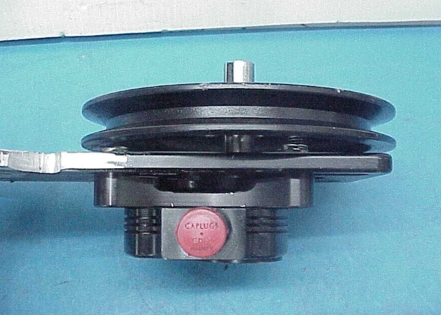
This has been a back burner idea for me since bjhines installed one 17 years ago. Last year I installed an oil cooler thinking about doing track days (LS engines get the oil HOT) and so now I think is the time to get the diff ready for track duty as well. Here's John's thread: I'm finally getting around to doing one for myself. I am not a fan of the Tilton pumps, they're expensive and so I started asking around and I got some good info on pumps, so thought I'd share my findings. NASCAR runs mechanical pumps off of the pinion, using essentially a single stage dry sump pump. These are run with a V belt, and then you put some sort of pulley on the driveshaft or the pinion flange. This has a couple advantages, mechanical pumps are gear driven not electric motor with a diaphragm, so should be more reliable. Don't have to remember to turn it on. If you buy the pump used, it's pretty cheap. I bought a pump with a 6.25" pulley and bracket that bolts to a 9" Ford diff for $100. No fittings, no lines, no cooler, but it's a start. When I had my driveshaft built I screwed up my measurements and it came out a bit long. It fits, but just barely. Plan is to take the driveshaft back out, have it shortened, and then either modify a pulley to bolt in between the pinion and the shaft, or weld the pulley either the shaft or the pinion flange, depending on which works out better in the space. I'm still considering how to mount the cooler, how to feed it air, and how big to go. I definitely want to go bigger than John did, as he measured 350* AFTER installing the cooler, at the end of a 20 min session with the 6 cyl working to build the heat. Katman had described breaking the needle off of a 325* gauge in a session with a 6. I want to install, and not worry about cooking the diff again. I have the fuel cell and Accusump offset to the right side to move weight. Thinking I have room to put the pump to the right of the diff, then can run the oil lines to the left side and have the cooler placement somewhere in the stock muffler area. Feeding air thru it effectively might be a challenge. Preliminary thoughts on cooler feeding/exhausting: 1. Put a NACA duct in the quarter window and run a 3" hose down to the floor (can go through the fuel cell cover, and then feed the cooler which sits horizontally. I have doubts that the cooler will flow a lot of air in this position. I don't have pressure readings, but I'm thinking that right behind the open window is not a high pressure zone, and the air will be exiting near the gas tank, which I am hoping might be sucked out by the wake under the car, but I don't anticipate a huge pressure difference. 2. Finally get off my ass and put a flat bottom on the car, at least between the frame rails, which is legal in XP. Plan here was to use thin aluminum, maybe .040" thick. I worry about leaks onto fiberglass or cf that is flammable. If I did the aluminum panel between the frame rails, then I could run some NACA ducts in the floor and maybe a pair of 3" hoses to the cooler, possibly making a fan shroud type of setup so that all the air goes from the hose through the cooler. I think this might be a better way to feed the cooler, but I'm still not sure about getting the air out the other end. Eventually will do a diffuser, and if I leave space between the diffuser and the body I think that the increased low pressure from the flat bottom and diffuser would help to exhaust the air out of the cooler. Might even be able to make an exhaust duct from the cooler to the slot between the diffuser and the rear valance, but I don't think I have the time/funds to do a diffuser and all of that ducting right now. Leaning towards #2, but any thoughts on ducting, the panel, mounting the cooler etc are welcome.
-
Gotta do what is comfortable. The adapter adds some thickness too, so if you got a wheel with the same dish as stock and then put a 1" adapter behind it, it's going to be closer than you want. I don't expect there are that many Z people you can ask to sit in their car in MN, but that would be the best option. Quick check shows spacers available, so maybe err on the side of too far away if you're in doubt and then use spacers to bring it back in if needed.
-
Just get an adapter for an S30 that fits the wheel you like. People without power steering commonly go 14". I found myself hitting the door panel when autocrossing, eventually went 13 and liked that better. Had aftermarket gauges, but didn't have any problem seeing them with the 13. It's been a while since I've shopped wheels, but Grant GT wheels have 5 bolts holding the wheel on, MOMO and most other aftermarket wheels have 6 bolts. But find the wheel first, that way you won't be exchanging the adapter.
-

Looking for 3.54 or 3.70 longnose R200 in the Seattle area
JMortensen replied to JMortensen's topic in Parts Wanted
Thanks. Found one last week. -
IMSA GTU vintage racer build
JMortensen replied to clarkspeed's topic in S30 Series - 240z, 260z, 280z
If you've got How to Make Your Car Handle, p3 (first page of actual writing) has a Z on 13s next to a stock one. Always wanted to do it, eventually ended up with brakes too big to make 13s work. -
Adjustable Camber/Castor without cutting! S30
JMortensen replied to Ont240's topic in Brakes, Wheels, Suspension and Chassis
I ASSumed it would be a carriage bolt type of setup installed from below, with the stud sticking out of the top. Looks like a plate goes underneath. My bad. -
Adjustable Camber/Castor without cutting! S30
JMortensen replied to Ont240's topic in Brakes, Wheels, Suspension and Chassis
Nothing missing. The slots fit under the stock strut tower. Loosen the bolts and you can slide the plate in or out to adjust camber. -
Looking for 3.54 or 3.70 longnose R200 in the Seattle area
JMortensen posted a topic in Parts Wanted
Just what the post says. If you have one for sale, DM me. -
Don't have a diff for you, but if you're still looking it might help to know that you can take the threaded buttons out of an R180 with bolt in shafts and use in an R180 that had clip in shafts.
-
Adjustable Camber/Castor without cutting! S30
JMortensen replied to Ont240's topic in Brakes, Wheels, Suspension and Chassis
Check the biscuit style camber plates, second and third listings on this page: https://www.dpracing.co/datsun-z-front-suspension-1 Design Products has been making Z race parts for 3 decades, maybe 4, not sure. I never used these, but suspension guru John Coffey used them and always talked them up. -
Yet another Rear control arm design
JMortensen replied to tholt's topic in Brakes, Wheels, Suspension and Chassis
The problem is that there is a transition from the strut top to the area between the wall of the cabin. I'd be putting my camber plate right in that spot. I suppose I could cut out the entire strut top, lay a new piece of .120 sheet in there and put a gigantic slot in it and have 5 degrees of movement or something like that, and then just weld it to the plate on top of strut area and the regular strut area. That'd be weird, but I think doable. Might be a lot of cutting on the underside of the plate that is in there now. I seem to remember a little pocket in that spot that I plated over. -
Yet another Rear control arm design
JMortensen replied to tholt's topic in Brakes, Wheels, Suspension and Chassis
I thought about welding a clevis to the rear of the upright and then being able to adjust roll center with spacers. I think you had brought that up years ago. I like the "fix it at the top" idea though, I think that's going to be simpler, won't have to mess with the CVs, etc, so that's the plan for now. Just need to disassemble so that I can get the camber plate shape and then work backwards to make an offset spacer. Was thinking of drilling and tapping the spacer so that I could move the camber plate to the stock position and then 1" back, and running studs in the top to bolt to the chassis and bolting the camber plate to the bottom. Might be a little tricky getting the plate to move far enough without the strut top hitting anything, but I suppose I've reinforced enough in there that I can hack some metal away without affecting things too greatly. It sounds easy from the office chair...