

carbuilder723
-
Posts
51 -
Joined
-
Last visited
Content Type
Profiles
Forums
Blogs
Events
Gallery
Downloads
Store
Posts posted by carbuilder723
-
-
18 minutes ago, Aerodynamic said:
Been following your build for a little while and I just wanted to say excellent job on your continued progress. I have a wrecked 2005 M3 and have been planning this swap myself for some time.
Out of curiosity, what are your plans/goals for the use of the car? Will it be a more track focused machine (chassis reinforcement, minimal interior)? Purely a street car? Or of course, a mixture of the two! Thanks
Thanks, I appreciate the complement!
My goal is realistically to have a fun street car. But... I do want some key systems to be up to the task of track duty should I want to do that also. (Fuel cell, Recaro seats, harnesses / half cage, lots of cooling for the engine etc...).
I do plan on having AC and power steering in the car...the engine and transmission are mounted on OEM BMW rubber isolators, and the exhaust will be relatively tame. I want to be able to comfortably drive it so it will have an interior, albeit not the same as the original.
The other thing I've kept in mind a lot is trying to think about the serviceability in the future. I've tried to use parts that should be available for a long time into the future as well as think about the process involved with repairing something should it break down.
-
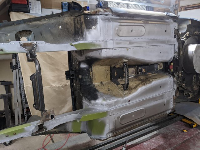
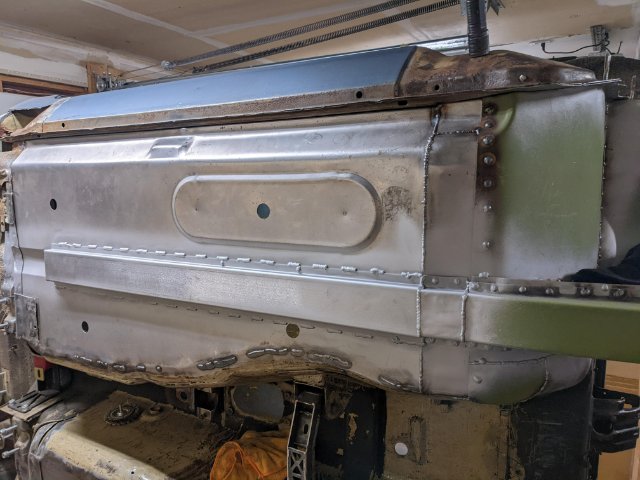
Got the frame rails and floor pans completely done! Used the Bad Dog rear frame rail connectors, KF Vintage front frame rails/battery tray / firewall, and Zedd Findings floor pans.

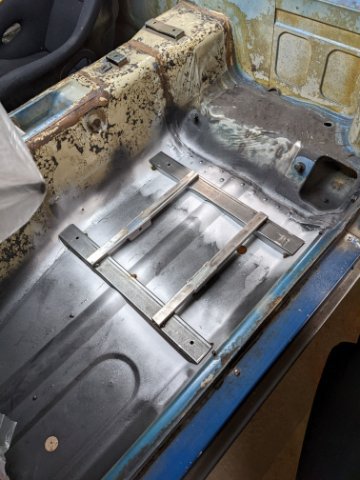
Finished up the seat mounts and briefly started to put some of the pieces back together. I included mount points for sub belts in the seat mounts.
Next up is the front core support and getting accommodations for all of my cooling needs sorted out.
-
It's been a while, but a lot has happened in the past year.
Not a ton of progress on the car, but enough to warrant a few pictures. On top of everything else, I moved, got engaged and changed jobs.
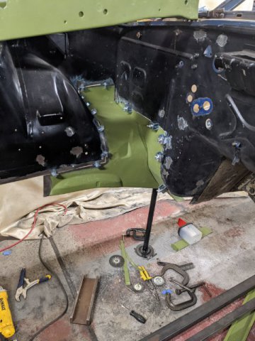
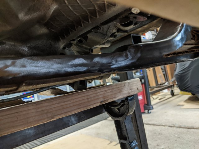
On the car, I just got one of the front frame rails completely replaced, along with the battery tray area and the passenger side firewall. I got the floor reinforcement in and the subframe connector in. I've just started working on the driver side and I expect it to go more quickly now that I know what the process is after learning on the passenger side.
-
potentially very interested in 15x8 +0 if that ever becomes an option
-
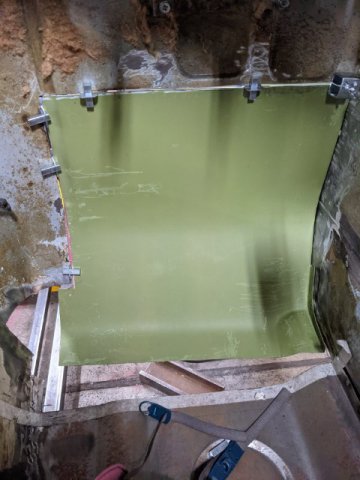
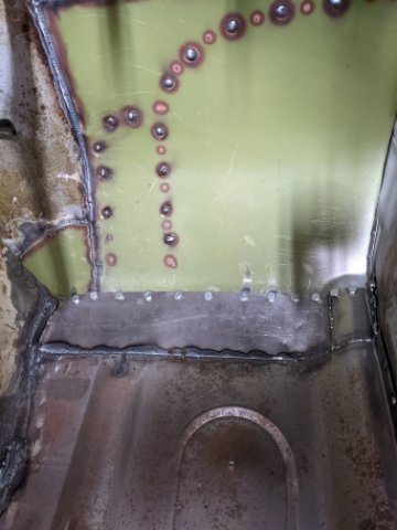
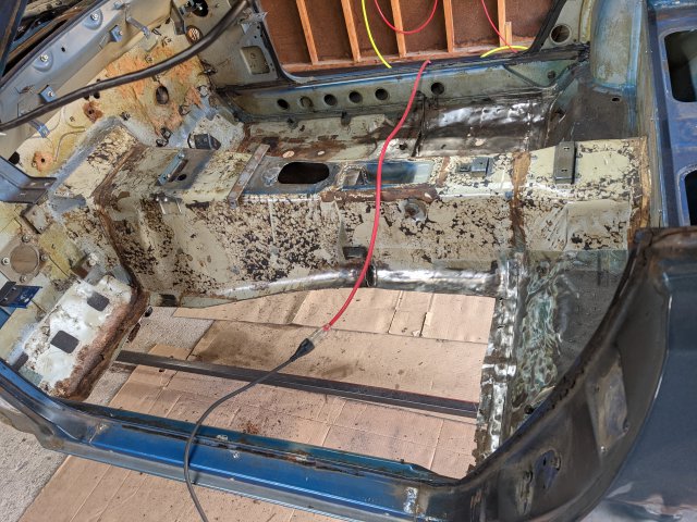
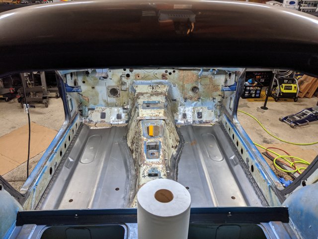
Floor pans are in! Mostly ...
They went in pretty well on all but the front edge at the firewall. I had some rust at that seam, so I had to cut the bottom part of that sheet metal out, which I'll have to get back to later.
Also the fit between the curve at the rocker and the existing metal was a bit off, but very manageable to massage into place. I butt welded the seam with the transmission tunnel and spot welded everything else (rocker and rear seam), After all of that, I have either one of two paths.
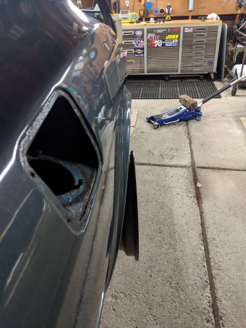
I found a little bit of damage to the passenger side forward frame rail, where it looks like the part closest to the firewall was pushed rearward about 1/4 inch or so causing a little wrinkle in the metal. This would basically lend me to replacing the entire front frame rails also, and while I'm in there, it would allow me to get to the battery tray area, and fix the firewall rust... So that may be coming soon, but I may take a break from the sheetmetal / rust restoration side of this for a small bit and work on the seat mounts for the Recaros to give me something a little more "fun".
-
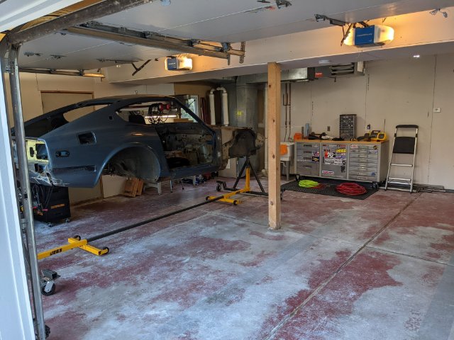
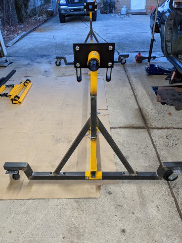
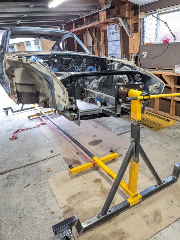
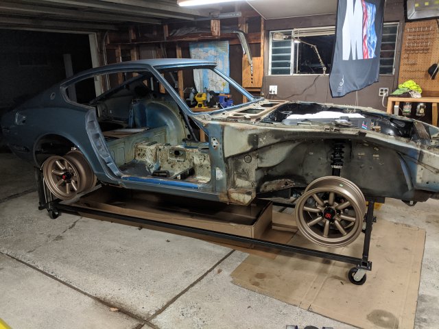
Holidays are over, some progress has been made. I got the car torn back down to the shell and started working on the rotisserie.
I used two Jeg's engine stands which were on sale and about $100 in steel to put this together. All in all, I think it came out pretty good. I can spin it around with one arm.
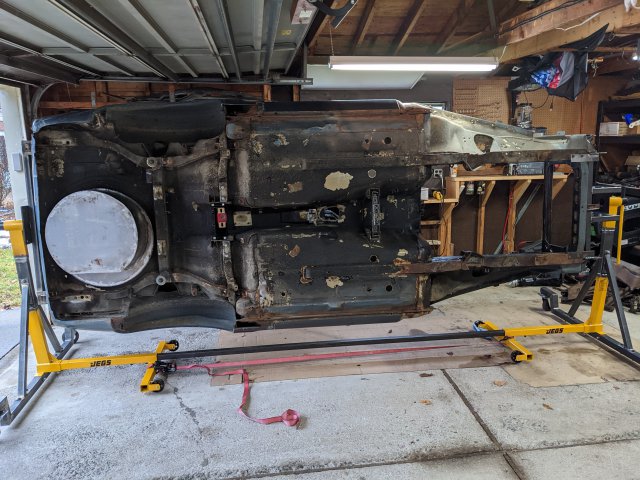
I got the garage all cleaned up, and ready to tackle the floor pan and frame rail replacement. Clean up one mess, before making another one.
Also, I finally got my final oil cooler. A CSF 8066, "The Boss" oil cooler. It should be plenty of cooling for any use this car will see.
-
Interested. Curious to see what the final pricing comes out to. I definitely need a windshield at some point. Hatch and doors I need to double check condition of what I have.
-
ECU was about $250 for an MSS54HP
Software and feature modifications and MAP sensor kit by Kassel Performance was in total about $900
Engine wiring harness was about $150.
There are probably a few other small things, but that should get you close.
@grannyknot... I should've asked before, but what did you do for radiator hoses?
-
4 minutes ago, AydinZ71 said:
Apologies if I missed it in your thread, but what are you using for timing and fuel management? Stock ECU or independent?
I'm running a stock, but modified BMW ECU.
It's had a lot of the factory BMW features disabled and a custom map uploaded to it to allow it to run as a standalone.
-
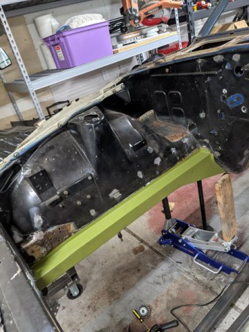
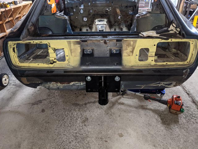
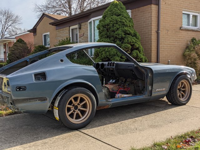
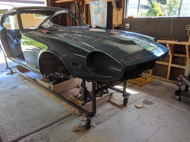
We have touch down. This is the first time the car has been on the ground in about 18 months... I think. It's sitting on all of it's new suspension with the powertrain installed also.
Next is going to be building a rotisserie and stripping the car back down to the shell so I can work on the floor pans and a few other body work items.
-
The AN fittings will have flexible hose between the fittings.
I have to try to make sure that there is enough hose to allow the engine to move adequately.
I can't argue the cost item though. -20AN fittings are not cheap, but it's a one time expense and it will go better with the whole build in terms of craftsmanship than spliced together rubber hoses would.
-
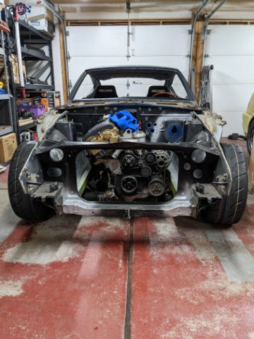
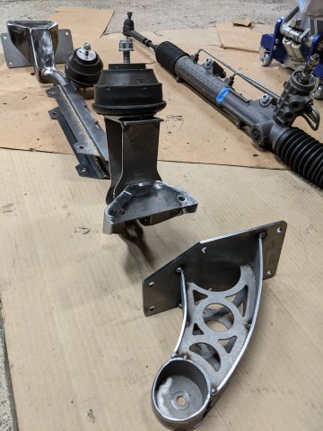
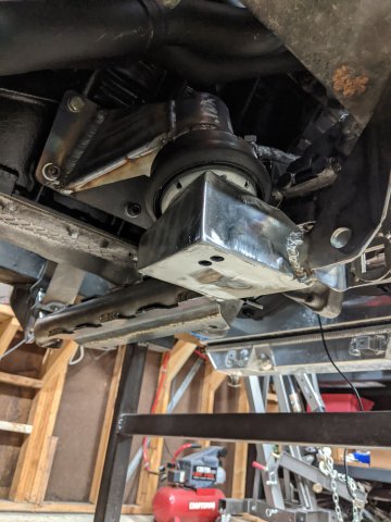
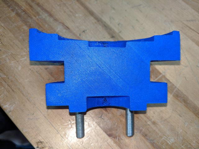
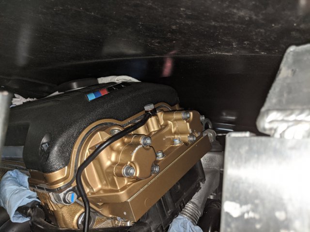
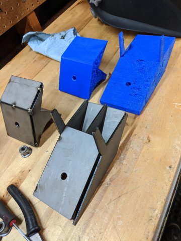
2 Months later ..... I've made some good progress, great progress really. I've been able to prototype 3 different revisions of actual engine mounts, and settle on a final version and fabricate them. I 've gotten the steering linkage sorted out, I put the pedal in for the first time with their lines connected to the bulkhead, and I got the engine wiring installed (very temporarily) and actually started it up for the first time in the car, with the whole drivetrain connected.
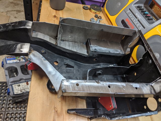
So, engine mounts first. 3D printer was working overtime again going a few different versions. I ended up straying away from the idea of welding to the frame of the car in favor of going with a solution more like what Nissan had originally done. I welded some support stand offs from my custom subframe to come up to meet the engine side supports and rubber isolators. I just couldn't bring myself to weld to the front frame rails and lose the ability to drop the engine out the bottom of the car.
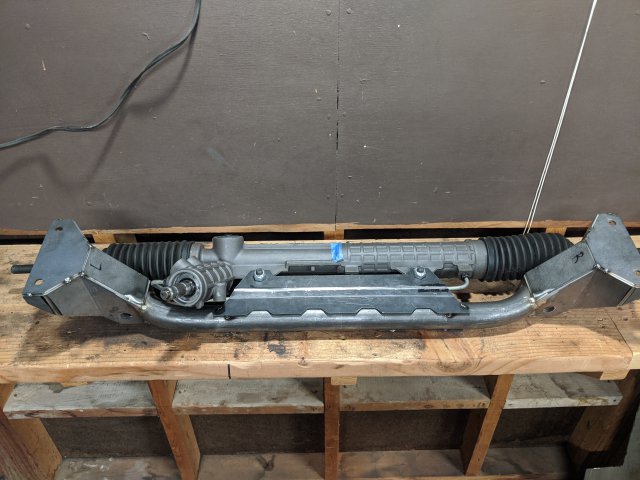
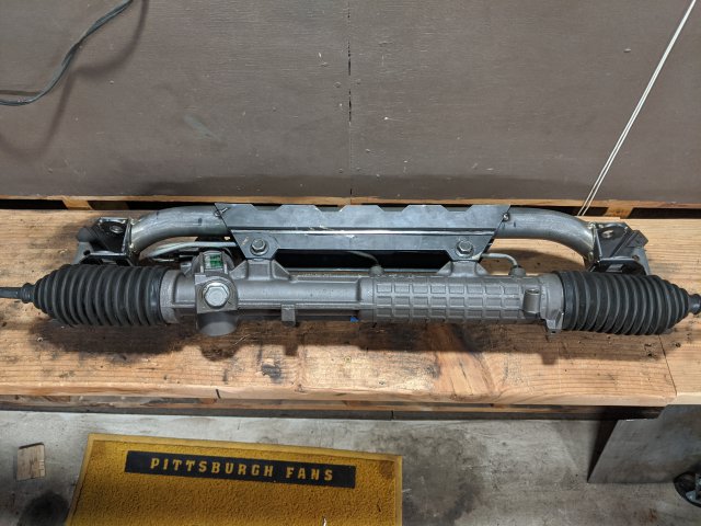
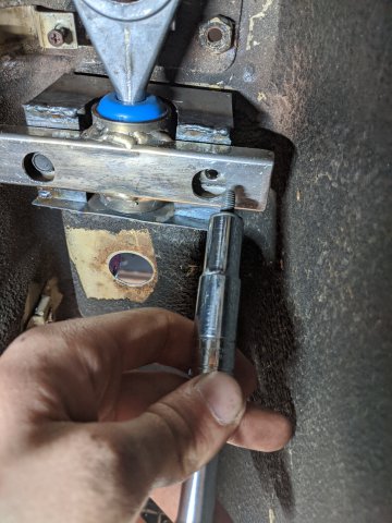
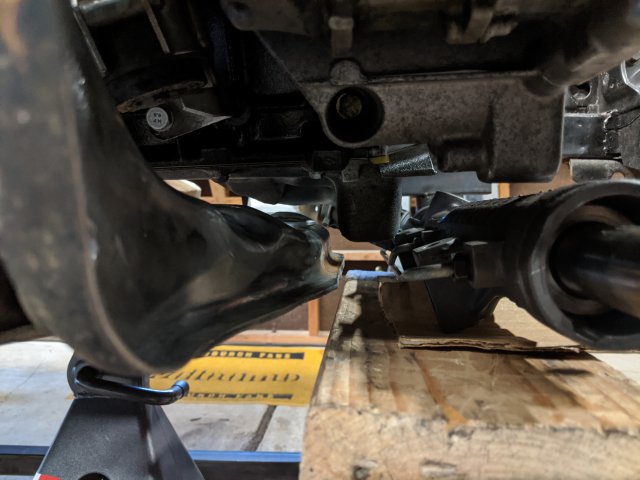
Next, since most of this custom subframe and engine mount work was to manage to get my BMW steering rack into the best position, I had to figure out how to actually connect the Datsun column to that BMW rack. It turns out that the BMW rag joint has a nearly identical bolt pattern as the original Datsun one, so that let me just take apart the BMW one and use half of it to adapt the Datsun column down to a 3/4" DD shaft. Then I found a collapsible DD shaft online (3/4" on one side, 1" on the other) that I used to connect from the steering column, to a Flaming River universal joint that has a 1" DD on one side and the BMW spline pattern on the other. I also am using a poly version of the original Datsun steering column coupler. Result?? The steering feels absolutely perfect... 0 slop from the wheel all the way down through to the tires. https://youtu.be/18_B0R0pzEc
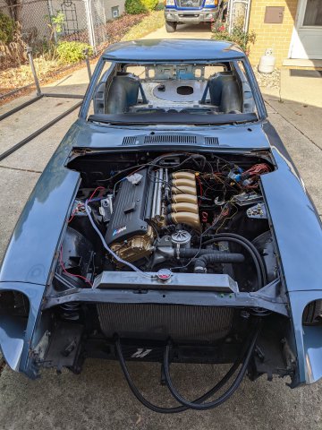
Once all of the engine mounts were fabricated, and the engine was finally sitting in its final position, I decided it was time to get it running... I dug out my box of wiring from the engine stand and started hooking it up. I put the dash in since it had all of my gauges and switches now and hooked those up too.
This was also a good opportunity to try out the new in tank fuel pump set up. (much improved in terms of the noise vs the externally mounted Boash 044) I filled up the coolant, topped off the oil put in a few gallons of 93 and gave it a try. First go, it didn't quite want to take, but I think there was just a bunch of air in the fuel rail. After a few more cranks, it came to life. Good stuff!
A few things coming up next... I made the decision to go with AN fittings for the radiator hoses, for a few reasons. 1) I'm kinda opposed to having to splice together a bunch of rubber hoses to get the shape I need. 2) Flexible radiator hoses aren't the aesthetic i'm going for. 3) despite is being a tough pill to swallow now $$ wise, it will make future trouble shooting or even modifications easier to adapt to a new set up if needed.
I'm probably going to leave the engine in for a bit longer, give it some run time since it hasn't seen much since last August (2019) and try to get a few things sorted out like coolant overflow tank location, oil cooler location, and maybe a few more plumbing things. Then it's back down to a bare shell to make a rotisserie and get those floors and frame rails replaced.
-
 1
1
-
-
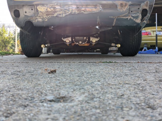
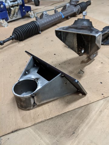
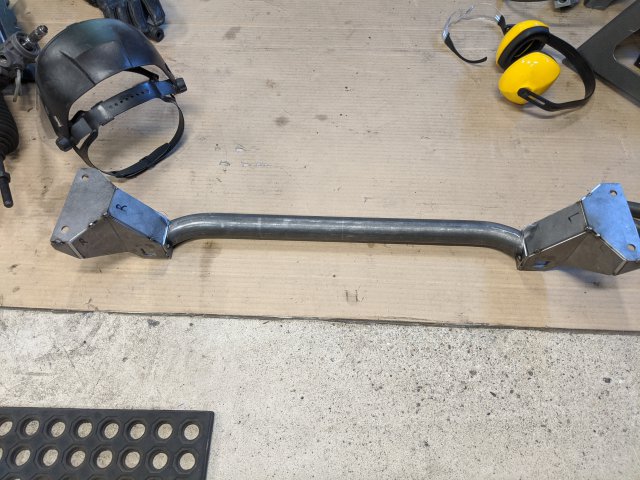
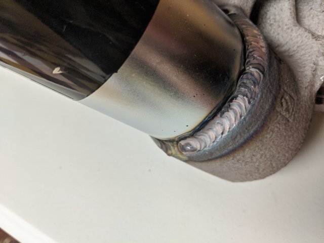
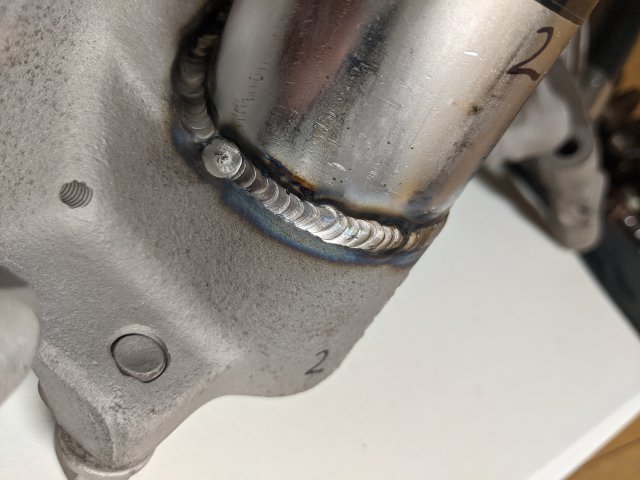
Sub-frame is done... at least it's all tacked together. And wow, not to pat myself on the back or anything, but I am thrilled with the way it came out. It couldn't be packaged any better in my opinion given the placement I want for the engine. I checked the bump steer again, and now instead of my laser drawing a horizontal line when going through the wheel travel, it makes a much more suitable vertical line with an acceptable amount of variation. There are some small adjustments I could do down the road to make it even better on the pitman arm / tie rod side of things, but this is going to be it for now. We'll see how it drives and go from there.
Onward to engine mounts... after some thought I think I'm going to try to a bit of a hybrid approach from what I was originally thinking. I'll get some more pics up, but basically, I'm thinking i'll incorporate the passenger side engine mount with this sub-frame and the driver side engine mount will be on the front frame rail. I think it's going to work better given the steering column placement and the environment. More to come
")
-
1
-
-
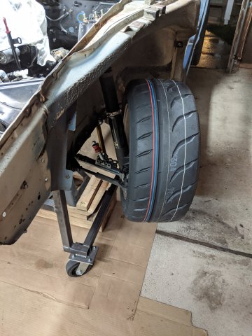
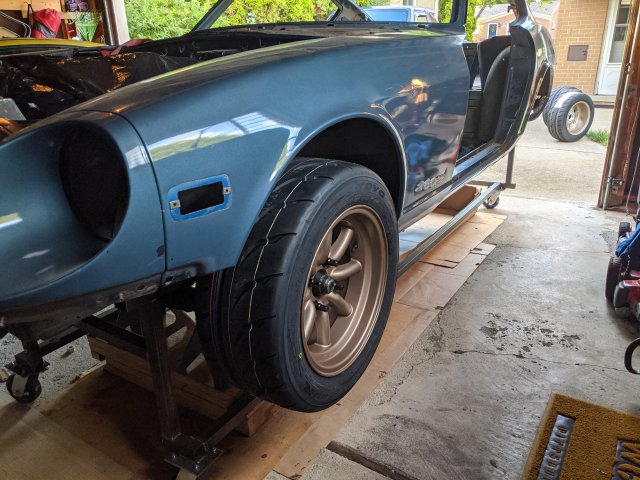
Back again. Couple more updates. I got the driveshaft adapter back from my machine shop. and it fits like a glove between the BMW CV joint and the r200 input flange. I guess my measurements were pretty good and their machine work was top notch.
I also went ahead and got the tires mounted onto my wheels and tossed them on for a brief test fit. Granted there's no sub-frame in the car to hold the wheel in place very much, but just hanging there, it's looking pretty good to get away with out any fender flares.
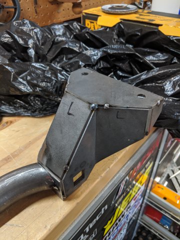
In front sub-frame news, I think I have all the pieces I need to finally get this thing completed. I have the tube bent, the steering rack mounts plasma cut and the end brackets all laser cut.
I used a new company for the laser cut parts this go around due to availability of my original source. OshCut is the name of the company I used this time and I was very happy with their whole process and at the end of the day their pricing was reasonable. It pays to have them cut multiples of what you need the first time, since it turned out that 2 sets of parts only cost about $15 more than a single set and the first set cost $80.
Anyway, I just need a solid day to trim the tube, finish welding up the end brackets and the steering rack mounts and I should have a functional front subframe. Then to readdress the engine mounts. I'm not sure if i'll use the frame mounted ones I already designed or if there is a way to potentially integrate them into my new subframe. 1 step at a time...
-
1
-
-
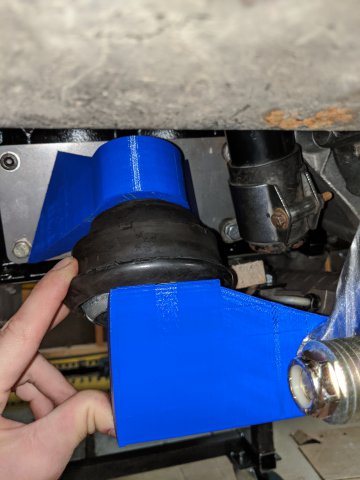
16 hours ago, Neverdone said:
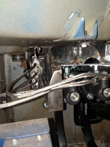
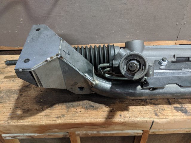
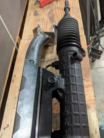
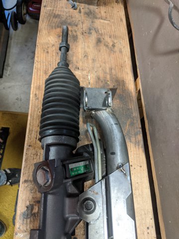
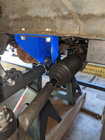
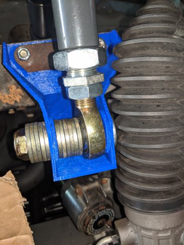
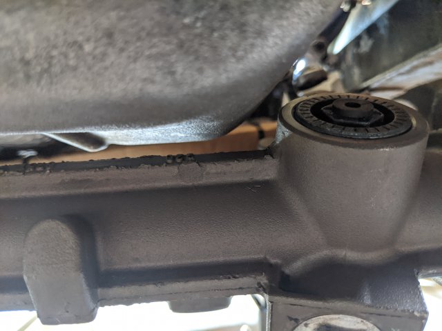
I'm usually for almost everything you do man...but the steering rack boots sure looks like it's touching the frame mount.
Even if it's not touching now, when the car starts vibrating and the suspension moves up and down, aren't you worried it'll wear a hole in it?
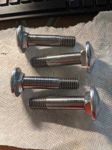
I am definitely keeping an eye on the clearance between the bolt head and the rubber boot. It is very close right now, but this is still all mockup. When I actually get the metal fabricated, I'm aiming to have at least enough space to fit my finger in between them (that is the minimum clearance I am working toward through out the whole system). If they do end up touching during suspension movement, I designed the joint using a custom carriage bolt that designed and had machined. Those bolts have a nice smooth, rounded head hence no sharp edges for the boot to catch. Hopefully that keeps the chaffing to a minimum.

-
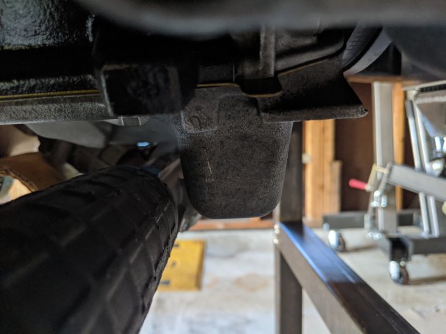
We're getting closer. I've gone through a few 3D printed revisions of some new subframe pieces and rev 4 is going to work pretty well I think (I hope).
The rack now lives behind the front sump on the bottom of the oil pan. This has made the geometry situation considerably better, although being very tight with clearance to pretty much everything. I've shrunk the bracket as much as I can, while keeping the pivot of the LCA rod end in the same place as it would have been originally. I've just given up the ability to use the washers to shim it any further forward. I included a picture of the CAD that I am working with (the big cylinder is just a basic representation of the steering rack)
-
Update time:
Drive shaft adapter was sent out to the machine shop, of course after one more revision and 3D printed mockup with the actual differential and CV joint.
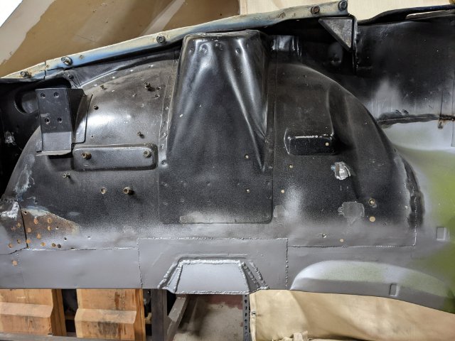
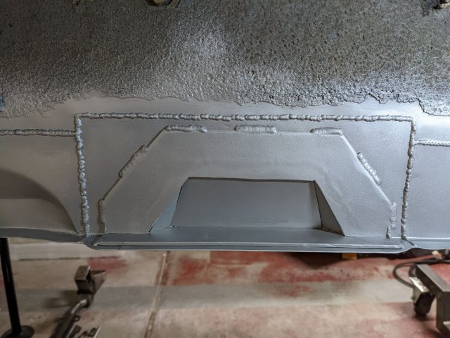
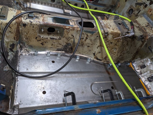
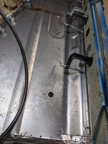
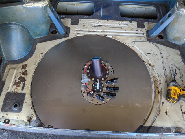
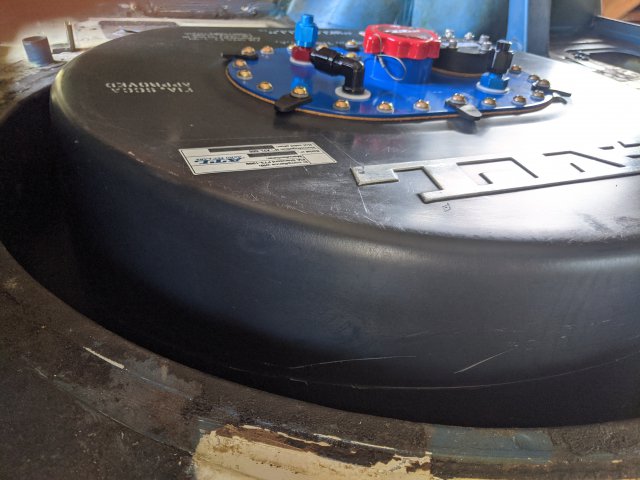
Fuel Cell Enclosure in the rear floor pan is complete. The steel is all 16 gauge which is, let's say significant... I probably could've easily gotten away with 18 or 20 gauge and cut the weight down substantially, but I figured having a little extra weight on the rear axle isn't the worst thing and it makes for an extremely stout enclosure.
Fuel cell top plate was designed, and laser cut with the custom holes layout. I had an extra hole added for a second pump should I ever want/ need one, along with a 4 wire bulkhead to let the power in to the pump(s).(ignore the backwards filler neck.. i need to spin the whole top plate 180deg).
Designed and fabricated a rear shifter bushing mount, with some captive nuts of course so you can just rotate it up into place and screw it down. Along with that I trimmed the shifter opening to give the shifter a bit more clearance. I still kept all of the holes around the opening, but gave it a bit more breathing room.
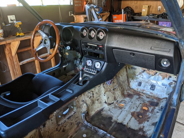
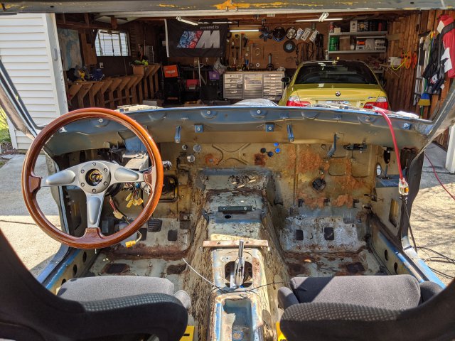
Test fit the new dash along with the adjustable pedals, steering column, center console, seat etc. This was one of those things that while completely unnecessary, I had time and i think it was worth the effort to remind myself that there is indeed a car in there somewhere. I also wanted to confirm that I would still be able to reach the switches at the base of the center stack that I added. Confirmed! Also helpful was I put the fenders and hood back on to check for hood clearance to the engine... good new... lot's of room under there for a strut brace.
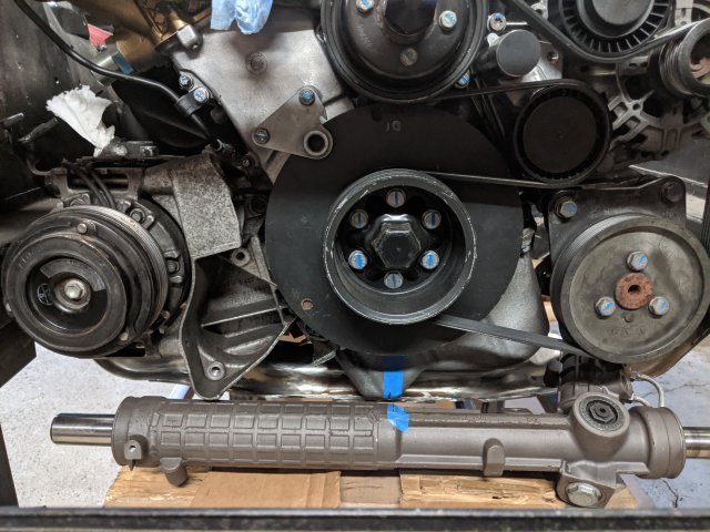
Lastly, I designed some new engine mounts that will get welded directly to the frame rails (I think). This is all in an effort to make room for the power steering rack, which while it is currently mocked up with a few spot welds, it has horrifying bump steer in its current position. So, I am churning through a few ideas in my head to try to pull the rack back towards where the OE Datsun one would've been. More to come on that. (Tubular front cross member anyone???)
But in the mean time, I did cut off the original steering rack and engine mounts from the front cross member in addition to sectioning out a portion in the middle to give more clearance below the front of the oil pan. Right now the engine is sitting nearly perfectly (on stands) but it's low, and pushed back to the fire wall as much as I want it. Now I just need to package the mounts, steering rack, and steering column around it.
So next up is still kinda the same thing ... getting the new engine mounts developed more and trying to do everything I can to get the bump steer situation better.
-
On 5/11/2020 at 6:25 PM, grannyknot said:
It's coming along well, are going to use the throttle by wire pedal?
Yup. I'll be using the electronic pedal. Since I'm not going full stand alone, there wasn't a great way to get the manual linkage to work. On the engine stand the electronic pedal worked great, and there is a pretty simple mounting bracket that the pedal comes with.
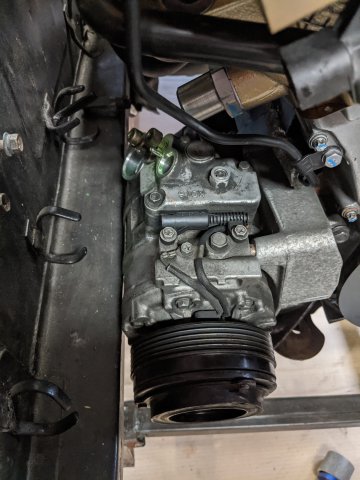
I've got another pretty big update coming soon. I'm going a bit off the reservation with some new engine mounts, modified front cross-member and steering rack placement. It's been a bear to get the BMW rack fit in to this car. The only other time I've seen a BMW rack installed was in a right hand drive set up, with out AC. But since I want it all, I have the AC compressor, power steering pump and original engine mounts all fighting for the same space. More to come....
-
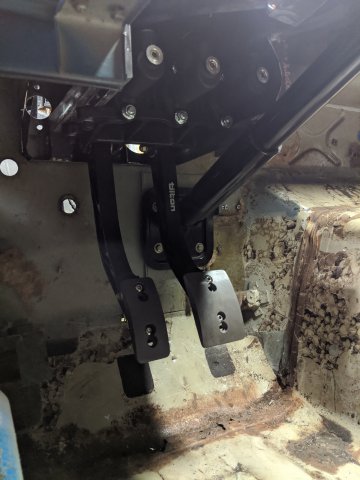
video of the pedals... just double click on it to fix the display issue. When I uploaded it, it appears massive.
-
For those of you still following along, The past few weeks have been pretty productive. I took step one to see if I needed to go the custom camber plate route, and cut out the strut tops to all the BC's a bit more freedom. Turns out, it looks like these plates are capable of well north of 3 deg of negative camber, especially when paired with the adjustable lower control arms from T3. So, for now, i'm going to leave the front and rear strut towers cut like this and just use the BC camber plates, and not cut more than I need to.
Next, I played around with getting the fuel cell mocked up. I had to cut out the whole spare tire tub and decided to fab up a new one that would allow the cell to sit lower, while still not protruding below the rear valence. I made some CAD files of the new enclosure and sent them out to get cut, so we'll see when those are done given the lock down situation still being pretty restrictive. Basically the way it's going to work is the black top surface of the plastic tank will sit flush with the rest of the floor, and there will be an aluminum cover that covers up everything except for the center top plate with all the fittings and such. Hose routing still needs to be finalized, but I have a few thoughts about that.
The project I kept working on was the Tilton Pedal box. I finally got everything cut out of steel and welded up to the original pedal box frame and I'm pretty happy with the results. Just needs cleaned up, and painted and boom... adjustable pedals with individual master cylinders.
-
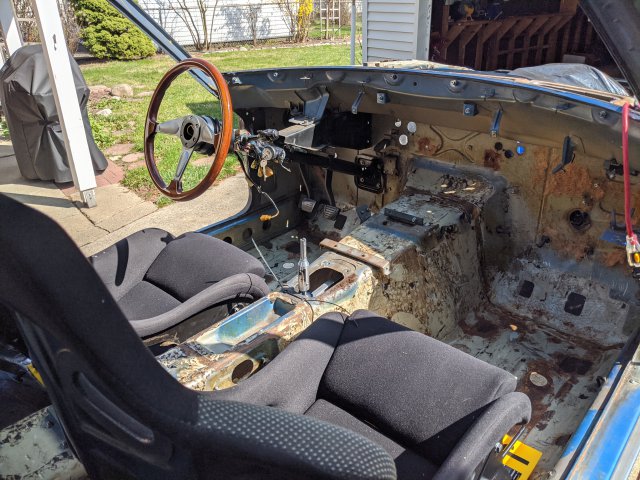
Hey Everyone!...Good progress being made. I finally took all of the wheel assemblies, control arms, brakes, etc and got them all installed onto the car which definitely brought some life to the project for the first time in a long time. It's got wheels!! (no tires yet, but let's ignore that) I also took the Skillard radio delete plate, drilled a few holes for my switch pack, push start button and extra AFR and Voltage Gauge.
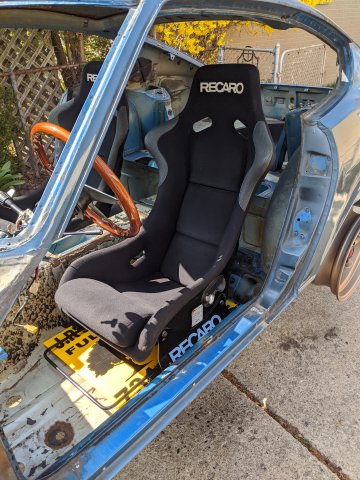
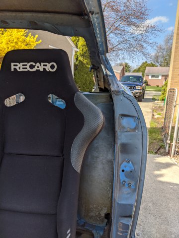
I also finally finished removing the original seat mounts and put the Recaros into position. Granted, for now they are just sitting on the floor, but I don't have any intention on the mounts for the seats being any taller than they need to be to get a wrench in to tighten down the bolts. I'll put some pictures up once the mounts are done to document what I did. In the same day, I put the steering column back in (with new wheel and quick disconnect) along with the shifter and old pedals to get a feel for how the ergonomics were shaping up. I have to say I was extremely pleased. I had ample head room, the steering wheel came to just the right place as far as distance and height, and to top it all off, the shifter fell exactly where my hand naturally falls to coming off the steering wheel. It'll need a bit of a notch on the original shifter opening to give a little more clearance, but overall I'm very happy with the current situation.
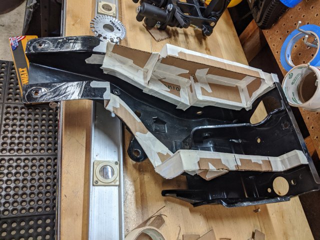
The original pedals did leave something to be desired though as far as position though as my legs were a little cramped up with their current position. Luckily, I planned to retrofit in a set of Tilton pedals anyway, which will let me move the pedals closer to the firewall giving my legs a bit more room to stretch out. Some of my progress into that process is pictured with some more CAD (cardboard aided design)
I also decided to put my fuel pump into the fuel cell. That lead to the decision to get a smaller Deatschwerks unit vs the Bosch 044. This should be quieter, and recirculate less fuel than the Bosch which was way over-sized as I eventually realized.
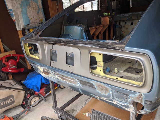
Decided to pick up a set of 240z tail light panels than are in fantastic shape. I'll eventually get the lamps to match but for now, they look nice just sitting on the car.
Lastly, I went to fit the BMW A/C compressor and I'm about 1/4" away from it fitting up against the frame rail. I'll probably need to bump the engine over to the driverside by about 0.5" with my rev2 engine mounts, which will help center the engine better at the same time and get the driveshaft pointed more toward the center of the differential input.
-
QUick Update:
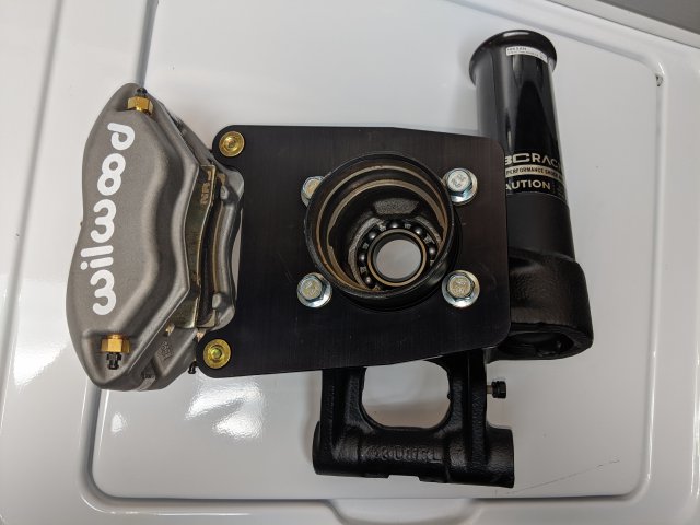
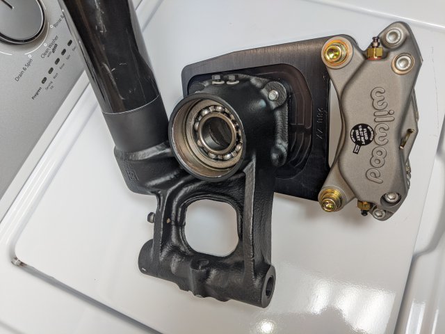
Got the rear brakes in the mail and mostly installed. Just need to grease up the stubaxles and install those now that the caliper brackets are installed.
Piece by Piece...
-
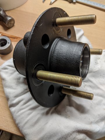
well, back at it. Couple of updates today... lots of pictures too.
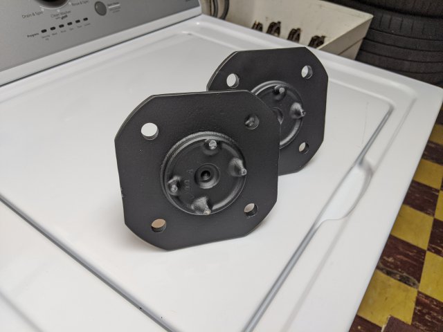
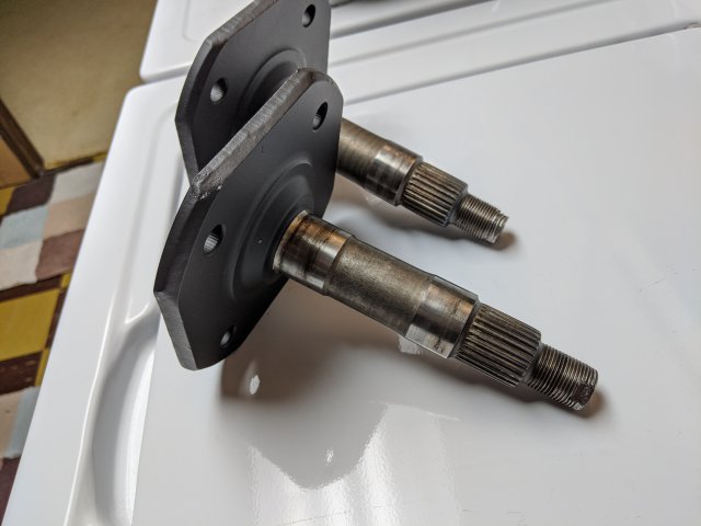
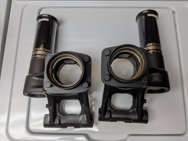
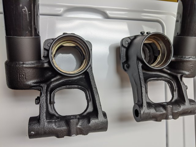
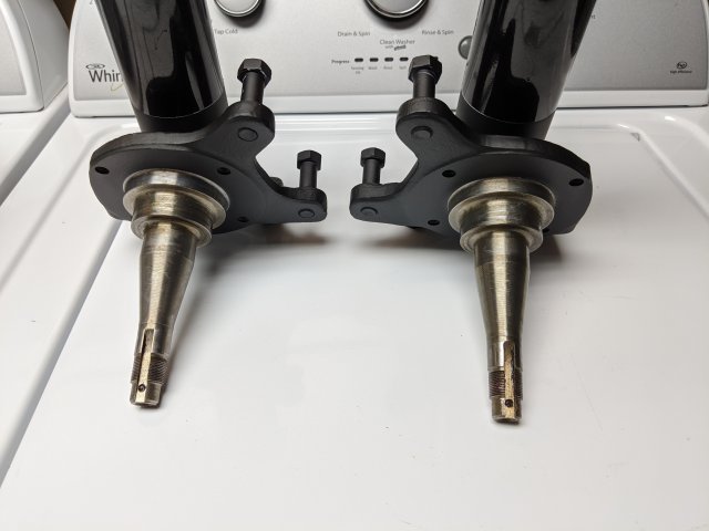
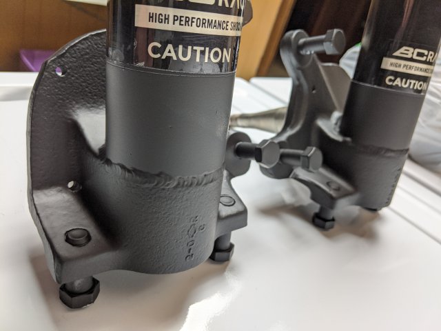
I got the BC coilovers welded up, and painted along with the front hubs and rear stub axles.
I also got the bearings and wheel studs put in and am just waiting on the rear brakes before I put the rear assemblies completely back together.
I also got the gauges all mounted up in the new dash, aside from the AFR gauge and voltage. Those 2 will go down lower in the center stack below the climate controls.
Alright so... in order...
Coilover sleeves welded to the original knuckles.
Everything all prepped for paint.
Everything all painted up. I just went with an industrial Primer and Flat black top coat (2 coats primer, 3 coats top coat). I went pretty heavy on the coats to try to give it the best shot at durability. It's not powdercoat, but I think it'll hold up reasonably well in the conditions I'll be driving in.
ARP Wheel Studs and Lug nut test fit onto a wheel
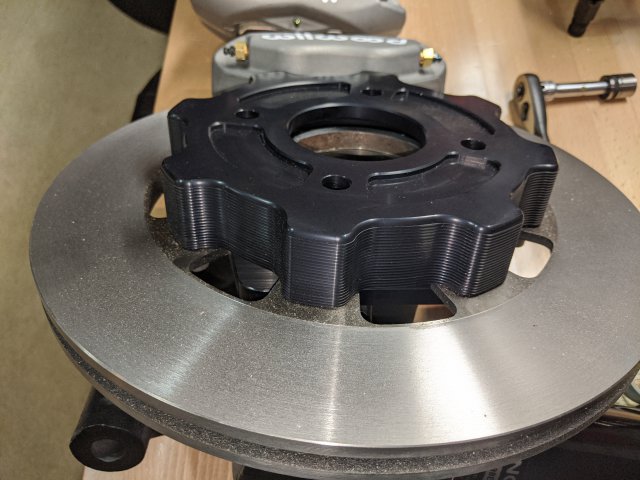
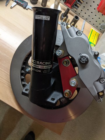
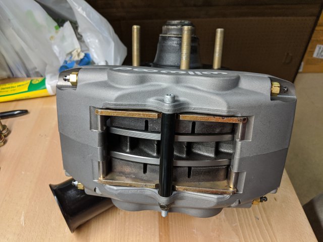
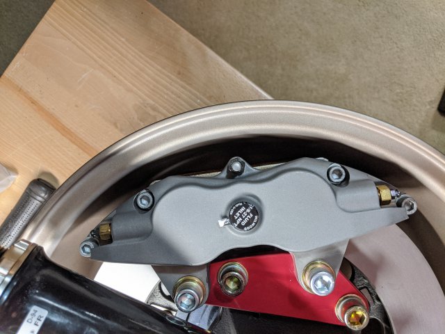
Arizona Z car front brakes installed and fit into the wheels like they were meant for it. Plenty of clearance in all directions.
I'll post up a few pictures of the rear brake kit when it comes in, but for the most part, this pretty much wraps up all of the wheel assembly work.
Here's a few pictures of the dash with all of the gauges. I used the Skillard adapters for the larger SpeedHut gauges and the smaller ones are using some 3D printed adapters from a fellow on one of the FaceBook Groups (Nick Clark)
Next is to keep working on putting the dash back together, but then, like I mentioned before, I'll be getting back into the heavier fabrication work on the car itself.
Spring can't be here soon enough ... and if Covid-19 could just go away, that'd be nice
-
Yup, I will definitely be moving the rack down from where the original would be since I need clearance to the front sump of the oil pan. You're right on with the mounts, they should be pretty straight forward. Once I have a mocked up location I'll have some brackets laser cut and weld them to the sub frame.
It is just a delicate balance with placement. I want to make sure I'm not going to induce any weird steering characteristics by moving the rack.


BMW S54 into S30 Chassis - Build Thread
in Other Engines
Posted
@Aerodynamic The reason I ended up going with power steering was pretty much only to avoid having to crank on the wheel so hard in the parking lot/ driveway. Also, I have an M3 already and love the steering feel in that car, granted it's is a much more modern suspension design. I also already had the power steering rack sitting on the shelf, so I figured, "why not?".
The custom front subframe was a combination of a few factors... mainly I wanted the engine to be down low and as far back as I could reasonably expect. I started by modifying the original subframe, but found as I went deeper into it, that it just wasn't going to allow me to accomplish those two goals, in addition to fitting a power steering rack in also. So, I bit the bullet and just went custom.
But don't worry, if you still want to do the engine swap, it is possible to do it with a modified stock cross member. If that's the way you go, I would keep the original steering rack and just position the engine around it.
@grannyknothas done a similar swap.
Another thread I've used as a huge inspiration is: https://retrorides.proboards.com/thread/139679/bmw-m3-powered-240z