
clarkspeed
-
Posts
840 -
Joined
-
Last visited
-
Days Won
29
Content Type
Profiles
Forums
Blogs
Events
Gallery
Downloads
Store
Posts posted by clarkspeed
-
-
Bleed F and R simultaneously? Don't understand. Usually the balance bar self adjusts and allows you to bleed each wheel as normal. Feels wierd, but works fine. I don't do anything different with dual master as I would with a single.
Let me know what you are thinking. Usually a non issue getting rear too strong. I tend to experiment with rear pad materials if things are too outa-whack. I have run street pads in rear before.
-
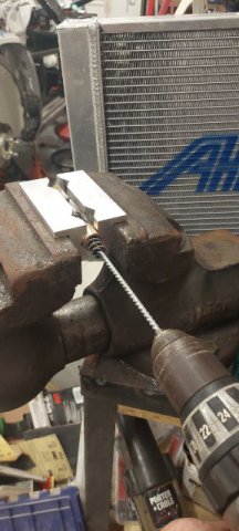
Couple pics. I had to fab my own pilot bearing. Bought something close from MacMaster Carr. Drilled it and honed the last .003" out to fit the tranny input shaft.
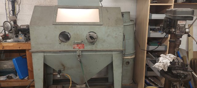
Also got a very large blast cabinet into the shop on a trade. Next job is to blast another set of strut housings for paint and then the exhaust system.
Many more pics coming.

-
On 9/7/2023 at 4:22 AM, jonbill said:
Surely your moustache bar is back to front?
What he said.
-
Cool.
With this type of build I would expect shimming the body somewhat just because the body may not be true. I hope your final assembly is visually acceptable.
Curious what you are shooting for for Ackerman. With the steering rack located in front of the front axle, you are limited on Ackerman %.
Good luck.
-
Sorry you are having to go through such a extensive quality inspection, but the time spent should pay back later. Some comments.
1. Record all your measurements and if you can add a feature to make it easier to repeat the measurement it will save time later. Like chassis center.
2. Are your bump steer measurements all in mm? A good goal is less than a mm over roughly 25mm of wheel travel. I think I would rather have the final rack in there to pass judgement.
3.might be easier if you jack the chassis and keep the wheel fixed to measure bump steer.
4. I didn't fully understand your chassis alignment issue but sounds like the control arm inner pivots are aligned and centered both front and rear? Just not square with frame? Not cool, but if the mounts are all aligned then kinematically the suspension should work as intended. Usually critical frame measurements are taken from the suspension mounts front to rear and X cross.
5. Looks like you have standard GM control arm bushings in there. Are they rubber? If so you might be getting some flex in some of your measurements.
6. Not sure of your ultimate goal, but if you plan on making a lot of alignment changes in the future you might consider recording all the coordinates and putting in a software program to simulate the impact of your changes instead of measuring after each change.
-
See above. R180 moustache and R200 are different and can be mounted backwards I think.
Always good to check if halfshafts are in alignment. You will also need to match angle of diff with angle of tranny equal and opposite.
-
On 9/2/2023 at 3:36 PM, AydinZ71 said:
Hey @clarkspeed.Bummer on the re-work and fit-up issues. I know how you feel! I’m experiencing similar difficulties, but I’m relying mostly on the OEM geometry. The sway bar is the only 100% custom aspect of my suspension.
I placed my regulator mount too close to my filter and have to do a loopty-loop of hose to make the connection. Annoying, but not worth the extra time just to make it “look” right. Hope you get everything worked out!
speaking of bump steer spacers: Greg said he had two 1” AL pieces welded together to get a 2” spacer. I guess Sam Neeve struggled to get his bump steer correct. I’m starting off with a 1” (since that’s the biggest off-the-shelf unit) and going from there. I found plenty of tutorials on setting roll center, but I have not found a decent one specifically for McPhersons yet. Let us know how you end up dialing that in on your car.
If you dig around on the forum you can find an excel roll center calculater I posted awhile back. It works for S30 z's. I still use it for a quick estimate. Yes, Greg uses 2 spacers welded together, and he runs a very low ride height. But I don't know what his front RC height is. I could probably guess. I'm sure it is above ground. And no trickery in the rear. His rear inner and outer control arm pivots are at or close to OEM location. Possible he runs higher RC in front than rear.
I have a 1.2" spacer I bought a couple years ago from TTT. I looked on their website and not see it for sale anymore.
-
On 8/31/2023 at 10:54 AM, jhm said:
Bummer, Clark…sorry to hear all that. You do one thing, and it affects ten other things. And the more custom you make it, the worse it gets! ☹️
At your convenience, would you mind elaborating a little on the control arm and steering geometry being “wrong”? (Causes, planned fixes, etc?)
Good luck with all the sorting!
On 9/1/2023 at 9:43 AM, jhm said:Nope....good explanation. How much caster are you shooting for, if you don't mind me asking? I'm guessing that remaking your steering rack adapters is a lot easier than making custom steering knuckles, as long as you can maintain clearance between the rack adapters and engine peripherals?
One thing I found when adding adjustable steering arms/knuckles and adjustable tie rod ends...using offset bump-steer spacers gave me extra clearance between the tie rod ends and the rims. Kind of like thick wheel spacers, without all the negative impacts of using thick wheel spacers. Without the offset, I would have had significant interference between the tie rod ends and my rims (15" diameter), like you described in your option #3 above. T3's new "evolved" design even has multiple mounting positions to tailor the amount of offset to one's specific needs.
I think I've got some spare 3/4" bumpsteer spacers (plain straight/non-offset) lying around -- you're welcome to them for the cost of shipping. LMK.
Thanks for the additional info!
I went ahead and bought a pair of 1" spacers not knowing any 3/4 existed. Let me measure where I exact need (nominal) to be and I will let you know.
-
10 hours ago, jhm said:
Bummer, Clark…sorry to hear all that. You do one thing, and it affects ten other things. And the more custom you make it, the worse it gets! ☹️
At your convenience, would you mind elaborating a little on the control arm and steering geometry being “wrong”? (Causes, planned fixes, etc?)
Good luck with all the sorting!
Sure thing. I will try to describe without diagrams. As you add caster, imagine strut top moving rearward, it raises the steering link angle with it. So the arm to tie rod link is now much higher in relation to the control arm ball joint. I did not plan for that. Didn't even cross my mind. So now, even with all my adjustability, I don't have a way to get the tie rod parallel to the control arm, which is needs to be close to eliminate bump steer. So my choices are 1) slot the inner control arm pivot down, not sure I have enough room 2) raise the steering rack, not possible 3) add more spacers to the tie rod to steering arm rod end, not possible, hits the wheel or 4) remake my adjustable steering rack adapters. I chose #4. I think there is a picture of them in this thread somewhere.
The control arm problem is a little harder to describe because of my design. I have a 1.2" bump steer spacer AND a pin below the steering knuckle that drops the ball joint, spherical bearing actually, in relation to strut and steering knuckle. This is all about control arm angle which drives roll center and camber gain. I have just a little TOO much correction resulting in a large downward angle on control arm and a front roll center quite high. To correct I need about a 3/4" bump steer spacer so I will mill down a pair after I am sure of the dimension it needs to be.
Too much information?
-
One step forward, ten steps back. Sorry no cool pics to post. Dealing with all my latest problems. Radiator outlet hits the alternator, oil pan hits the steering rack, exhaust hits the brake lines, control arm geometry wrong in front, steering geometry wrong, excessive bump steer, need a custom pilot bushing, new damper direction and renovate another set of strut casings, maybe more I am forgetting about.
Had to pull the engine back out and now methodically fix each problem 1 by 1. The immense frustration only lasted 3 or 4 days then back at it. Mentally hard pushing through 10+ major problems I didn't plan quite well enough for.
On plus side, all the plumbing and electrical done. Engine done, induction system done. Exhaust still needs a coating.
-
Or if you really want to be sophisticated, buy a throttle by wire pedal. I see many of the EFi systems support it now. Program your own linear ramp.
")
-
7 hours ago, tube80z said:
One thing you can try to make the ITBs more drivable is to create a progressive throttle cam so the throttle moves a lot less on the initial pedal movement. I had a car with light-switch SUs and this helped add some drivability to the car.
Cary
That is a great idea. That would make 50's work on street fairy well.
In my opinion only without direct supporting data, think a large TB with a highly ported intake on EFI makes max hp from a NA L6. My intake is ported so much I broke through the walls. I don't think I measured over 6 (in. Mercury?) Vacuum with throttle cracked open. I also highly suggest a VERY OPEN filtration system. Can't be too large. What are you planning upstream of the Jenvey's? I saw Troy Ermish put a 5" diameter cold air on a race 4 cylinder.
-
50mm ITB's! That will be an on/off switch, but I personally think will make the power. Forget the MAP.
Turbos are different. On a NA motor you can kind of sneak up on knock. You will hear and feel it with any muffler at all. Probably without. If unsure you can start with octane boost on top of premium and then back it out. I hate retarding timing on an NA motor.
-
A lot depends on your induction system. I have 48mm ITBs with a short manifold. There is not enough vacuum to do anything with so no MAP for me. If you are using a 1 into 6 manifold or a stock based manifold, definitely use it. And most of the race guys I know avoid knock sensors. Maybe they are better now but in the past false vibrations would cause them to reduce timing and power. Street car on the hairy edge may be needed.
I can't speak for the closed loop tuning stuff. I don't know anyone who has used it to tune a true road or drag race car.
I usually tune WOT fuel curves on a dyno. If really stumbling off throttle I might to a 1/2 throttle run. Then fine tune part throttle and throttle tip in based on data collected while driving.
Don't think I would spend any money upgrading an SDS. That would not be practical. This thread got me looking at the Speedduino again. I understand sensors, wiring, and Tuner Studio so much better now.
-
Believe it or not, I am still running a SDS on mine. Plans to upgrade but have not justified it yet. Lots of good systems out there now. I've also heard good things about the Maxx. Haltech has been a solid product for many years. Troy Ermish recently posted he dropped Electromotive because of lousy support. I've tuned Mega's and they are solid too. Speedduino looks really neat for a simple system. Really tough to decide based on features vs. price.
I think the higher level stuff gets deeper into traction control, wheel speed sensors, trans control, ABS, telemetry, and other motorsport needs. Top of the line is a Bosch. Most of the pro production race cars run them. I looked into their features 1 time and thought I will never use any of that!
Luckily any system that is good for the street is probably way more than you need for a 50 year old race car.
https://www.bosch-motorsport.com/content/downloads/Raceparts/en-GB/109903243.html
-
Need some more details to troubleshoot. Did it idle good before? What changed? What EFI computer? Do you have an O2 readout?
What kind of TB/intake manifold is that?
Also agree with your other post.
-
Nice work. That looks like a potential side business.
-
There is only so much room to work with. If the inside is a 1/4" or so away from your strut, then the outside edge will fall where it may. I usually shoot for 0 or a little interference on the inside and use a wheel spacer to compensate. Can't give exact numbers because tire size and suspension travel make a big difference. Once you go to a 8+ rim without flares every 1/8" counts.
Best to remove spring and jack wheel through full travel. If you already have the Rotas mounted up, you should be able to predict what a change in offset or width will do for you.
-
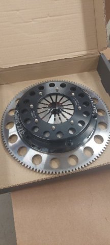
I've been working but not much to show. Dealing with many interferences in the engine bay. So it is all rework at this point. Hopefully some success and photos soon.
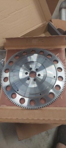
In the meantime, clutch parts arrived. Ordered the Flywheel from UK and it is a nice unit. Clutch is 7.25 Quatermaster 2 disk V drive. I went with 7.25 because my tranny ratios are soo tall. Pretty sure I would burn out a 5.5, just driving around pits. But not I need to order 8mmx1.25x45 bolts to mount.
TTVracing.com

-
Pretty awesome. I am going to download your pics and add to my collection!
-
I didn't know anything about this even though I have seen it done years ago. I did some -esearch on the net and this is what I came up with. I make no claims that this is acceptable or best practice. For new sensors you are installing:
To describe what I did for analog sensors, first I will describe the cable. It should have 3 small insulated wires, usually a plastic or foil (better) sheath around the 3. Then a braided wire shield around that and an outer jacket. I got confused trying to order but ended up with something that worked off ebay.
One wire supply voltage, one ground, and one signal. If splicing something with different colors, keep them straight. I use a lineman splice on each wire with a touch of solder. Then each gets a shrink wrap. If you offset the splices you can keep the final diameter small. See picture. Then I lineman splice the shield and touch with solder. Then a larger shrink wrap over the entire bundle.
For the "system" you need to ground the shield on the box end, not the sensor end. You need to solder/shrink wrap a small "pigtail" to the shield. I could only find this picture to show how that is done. In the picture they are using a crimped collar to hold the pigtail. I just twisted the 2 together and shrink wrapped. I then ran the pigtail and the ground wire to the system ground, not a chassis ground.
On the sensor side I had 3 possibilities.
1. For the motorsport sensors, I spliced into a connector with pigtails already pinned in the sealed connector. There are only 3 pins so I don't believe the shield continues across the connector.
2. For the 3 wire sensors I have, none of them have a shield. So I ended the shield at the weatherpack connector I installed.
3. For the 1 and 2 wire connectors, I use a 1k dropping resistor to convert the resistance to a voltage signal. I did this at the connector.
I think industry uses solder sleeves to do most of this and they even make sleeves with a pigtail built in.
I think that is more than what you are asking. For my TPS and tachometer, I just splice into the EFI signal wire and run in a different direction to a data logger. Seems to work ok. For temps I run duplicate sensors.
-
Stunning. Looks like a modern IMSA car.
-
The latest Grassroot Motorsports magazine did an article on low priced struts that are now on the market. Their already highly developed project car gained time by replacing Koni's with Redshift. Seems these builders are using cheaper manufactured components, but applying modern valving and customization. 2 of the companies mentioned include Redshift and Shaftworks. Both reside in the US and appear to have a weld in application for the S30.
https://store.redshiftmotorsports.com/default.asp
-
Shout out for help. Maybe there are some electrical experts reading. I am looking at expanding the capability of my data system. I am using a Race Technology DL1. I have 12 analog inputs which are fully utilized. It also has the capability to log multiple CAN channels on top of the analog sensors. Think connect to an OBD2 and log what ever channels you desire. But my custom race car does not have an OBD2.
My desire is to connect a couple CAN multi-output tire temp sensors along with a multi-output RS485 yaw sensor. Seems like Arduino hardware to support this can be sourced easily and I am familiar with using them but not writing my own code.
I think this requires setting up my own independent CAN network with H/L output to the DL1. It can be programed to read the CAN configuration. And an Arduino to convert the RS485 to the chosen CAN rates. Seems easy enough for someone who knows what they are doing, but hours of research on the net did not get me there.
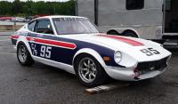
240z SCCA vintage race car, restoration
in S30 Series - 240z, 260z, 280z
Posted
Yea, I could see that happening. A lot depends on the volume of the slaves. Luckily there is more than one way to skin the horse.