katokid
-
Posts
51 -
Joined
-
Last visited
1 Follower

katokid's Achievements
")
Newbie (1/14)
0
Reputation
-
Took a while longer than expected Ron but got there in the end. Thanks again for all of your help.
-
Its the front bush for an RN90 Hilux rear spring 40mm OD
-
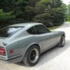
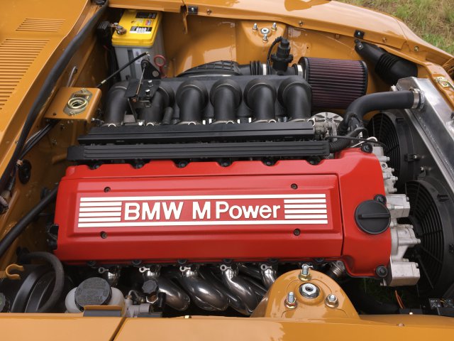
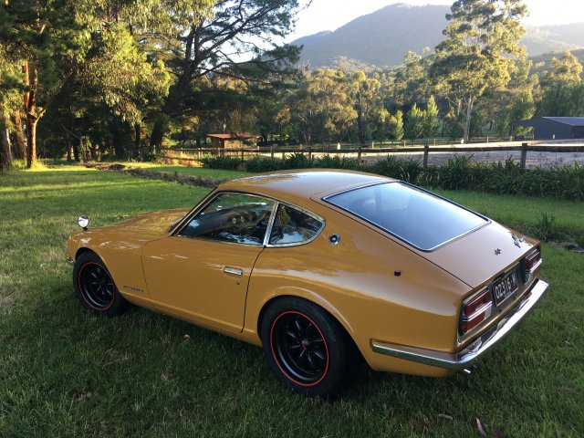
Kato, I'm just finishing up my S54 Z and thought you might appreciate a couple of pics.
I love your car,
Chris

-
Hi all. Apologies, I got so caught up in work and my build that I didn't have time to post here. Good news is that the car has been finished for a few years now and is an absolute blast to drive. No real issue to speak of and has been 100% reliable even on the racetrack. My full build thread here : https://www.viczcar.com/forums/topic/4654-kato-kids-bmw-m3-powered-71-240z/page/41/#comments
-
Thanks for the compliments. I like detail and love to see it in other peoples threads, no doubt there are some people that can do without the detail but hey you dont have to read it. Last bits I had to do before I returned the welder to my mate was the rear mount, the tip and the O2 bungs. The tip was a matter of measuring and cutting, creeping up on it to get just the length I wanted. I probably should have hung the rear bar on it to confirm it still looks Ok. Also included a shot of the rear mount before I added the tip.....not much room up there but it hangs just right. There isn't much room for the O2 sensors and I was going to put them further downstream where I had more room but luckily I did some reading up and they require a minimum of 600 deg C to work properly. They actually have heaters in them to bring them up to temp quickly so they can monitor emissions on cold start. The bungs are the same length as the factory bungs at 25mm and are pretty close to where they were on the factory headers so should be good. Also they must be pointing upwards from horizontal so that the water from condensation on start up doesn't collect and damage them.....the things you find out!
-
Thanks for the compliments guys. I haven't been completely idle but life and work just keeps getting in the way...I have been plugging away on the air filter and exhaust system. There was no way the factory BMW air filter assembly was going to fit so I had to find an alternative. Ended up with the only K&N filter in their range that had the required 92mm ID to match my MAF. Its pretty fugly and far from what I envisaged but it works and I'm constrained by the oil cooler lines that run underneath. There's a bracket which you cant see that supports the MAF and filter coming off the engine mount below. I thought of running a tube through the radiator support panel and having the filter out front in a set up like the standard 280 arrangement but the hole in the radiator support is way too small and I didn't want to cut it up. As Ive stated previously the factory M3 exhaust system is a dual 2" system all the way and the aftermarket systems pretty much replicate this but go up to 2.25" all the way . Everything I read says that Bimmers drone like crazy with a large single and lose the signature Bimmer note if you go away from duals so I was pretty committed to staying with this format if I could make it fit..... with the condition that I had to have good ground clearance. I didn't want to use chambered type mufflers so I need as much length and volume in the straight through designs as I could fit under the car and hope that will get me through rego and still sound good and be nice to drive....we shall see! I had a custom stainless mid pipe resonator and rear muffler built to my plans. Resonator is as long as space would allow, there will be two 12" hotdogs under the diff and then into as large a rear muffler as possible with dual inlets merging internally into a single 3" outlet. I bought a bunch of 304 mandrel bends, V bands, hangers and other stuff and got into it. The factory headers are double 3 into 1's with the secondary pipe being 2". In order to be able to remove and refit the headers in the car I needed to have flanges as close to the end of the secondaries as possible, there was little room so V bands were the only way. Down stream from the V bands it goes straight into a 2" to 2.25" cone and then eventually via many bends and sections into the resonator. The two bits of wood in the photos are there to position the resonator while I built the engine pipe(s) and they sit hard up on the chassis rail for the front one and the back one is spaced down the corresponding depth of the rail so the resonator sits level in the car. After many hours of work I'm very happy with the engine pipes and the resonator fitment. Ground clearances is not compromised at all ....but things may get a bit warm inside the cabin as it is tucked up very high and close to the tunnel. I lashed out and bought Vibrant Performance V bands from Summit and very glad I did....very well made, full stainless (cheaper stuff isn't) and they have this really cool flip on flip off quick connect feature for the T bolt. I couldn't tell you how many times I have removed and refitted them in the process but it was heaps and they work brilliantly. I borrowed a BOC Inverweld 140 http://www.twi-global.com/industrial-membership/industrial-members-showcase/products/boc-inverweld/ which is a small portable machine. Its really a stick welder but can be set up to use as a TIG however it has ZERO features (hand or foot amperage control, pre flow, post flow etc) that you normally find in a decent TIG. I had never TIGed before so figured I would tack it with this and have someone experienced finish weld but after a bit of mucking around and going down to 1.6mm tungsten's I found I could get a pretty decent weld from it so have decided to do it all myself. As long as you get very good joins with no gaps you can just fusion weld with no filler, most of the time I enjoy it but every now and then it gets a bit ugly but Ive learned heaps and pretty confident now. Ive used generic "Toyota" rubbers which use 10mm push on rods. Ive used cheap mild steel rods for the top rods that have been welded to my modified suspension/front diff mount cross member as they will be painted but had to spend $70 for 10x stainless rods for the lowers. Mounted at 45 degrees it relies on the weight of the system to keep things central. There is some lateral movement as expected but its not enough to be a problem (I think) given the tight tolerances (I'm working with half an inch as minimums) and they are nice and soft so hopefully should provide good NVH insulation. Its not easy to see but there is a step down from the exit of the resonator to the inlet of the hot dogs, required to optimize the ground clearance for the resonator and the positioning of the hots dogs to clear the R200 diff. Also required was the turned in exits from the hot dogs to clear the the rear suspension. The step down loses me some about half an inch of ground clearance but cant be avoided. Exhaust is virtually finished, just need to make the front mount for the rear muffler and do the O2 bungs. Its been a much bigger job than I anticipated. Making it a dual system makes it much harder because you have to mirror everything ...if its a single system there is no reference so it always looks right but as soon as you introduce a dual system you can see where things diverge or converge or don't match and look pox if you don't take the time, especially so for this rear section. If I was doing this again I would do it in mild steel and coat it, stainless is just that much harder to work with. The welding bit is fine its the cutting and fine tweaking to get a no gap join so that you can fusion weld is the really time consuming part as stainless is so much tougher (hardness) than mild. Anyway I'm pretty pleased with the way it looks....just hope it is quiet enough and sounds good!
-
Ron, thanks for the kind words. You've summed up much better than I could the way I feel about this project. I was so tempted to go with a more powerful engine (RB, JZ, LS) but so glad I stayed true to the NA in line six heritage of the early Z's. I just hope it runs true to your predictions and my aspirations! Thanks again for the inspiration and help.
-
I'm slowly working away on all the little things before I disassemble the shell and send it to off for final paint.....getting closer.... just the exhaust as the last major piece. The BMW shifter has an inner and outer seal. The inner seals on the base of the shifter fulcrum and the outer seals on the gear lever and to the body by means of a recessed flange in the boot. No bolts or screws....the boot just pulls through the tunnel and seals very tightly on the recessed groove. Fortunately the original hole in the Z tunnel is exactly the right width for the correct diameter of the round hole that the boot requires so I just had to add a bit at the front and the rear.
-
At least the clutch line was cheap. Two sections made up by Better Brakes in Bayswater......one from the master cylinder under the dash then behind the heater box to a firewall fitting which uses the original hole where the choke cables went through. Second part goes from the firewall down to the slave cylinder. BMW power-steering systems are renowned for overheating if the cars are tracked, most punters install a proper power-steering cooler in place of the typical loop of pipe (like most cars) that normally serves as the cooler. Under-driven pulleys are also an option but don't really fix the issue. Either way I couldn't use the original BMW loop of pipe due to a lack of space so a proper (albeit small) cooler was going to be needed. The original BMW loop cooler sits in front of the rack on the cross member and this logically is the best place for a proper cooler. I fabricated a bracket from 3mm plate that is welded to the lower front edge of the cross member and the cooler sits on top of that using rubber isolators top and bottom of the mounts. In the photos the bracket is just tacked for now and I need to get some nice stainless domed Allen head bolts and nylocks to finish it off. The cooler is the largest I could practically fit in the available space....Harmonic Balancer sits very close at the top of the inlet and outlet hoses which required the cooler to be offset slightly for clearance. Lines are braided teflon -6 from the pump to rack and then to the the cooler with a -8 hose tail and rubber hose back to the reservoir. M3's come standard with a pretty substantial engine oil cooler and there is a thermostat built into the oil filter housing where the cooler lines originate. The M3 oil filter housings and coolers are a popular add on for anyone modifying a lower spec M50/S50 series engine as they are a bolt on. The original M3 cooler is the same width as the radiator which it sits under but its only about 70mm high so its wide but narrow and again I couldn't use it as the front of the Z is just too small. In front of the radiator was the only option for me. There are three holes arranged in a triangular pattern on the front of the radiator support cross-member which lined up well with the Earls cooler I had chosen so like the PS cooler I used some 3mm plate to fabricate brackets and made the same rubber insulators as the PS cooler. Still need to add a lower bracket and the -10 hoses. Plumbing at the back of the car is nearly finished....new brake lines on both sides and new T piece from the front line. I'm using a Russell inline fuel filter where the braided line from the tank meets the hard line going forward. The filter is small and light weight but I didn't want to leave it just hanging off the hardline so I made a bracket to support it. The clamp will be insulated with some 3mm nitrile rubber to protect the filter. Second hard line is the return from the pressure reg and will connect with braided line to the tank. Time to run the engine oil cooler lines.... The factory oil cooler lines use a unique O ring set up which cant easily be modified, plus the factory cooler and lines wont fit anyway so Ive used an adapter made by VAC Motorsport that allows -10 AN lines to be plumbed from the factory oil filter housing. Getting the cooler lines through the radiator support was a bit of a mission. Had to keep the lines from rubbing on the inner guard, rad support and have the right angle for them to join the cooler so I made a bracket which bolts to the lower radiator attachment hole and used an overly expensive "billet" double hose clamp (which worked perfectly).
-
So, took my fuel tank to Melwide Radiators as there was plenty of rust and scale inside after sitting with no fuel in it for nearly 20 years also had a decent dent in the bottom and I needed the original fuel sender and pipes covered over. They quoted $400 to cut the tank in half, media blast inside and out, tin the whole of the inside so it wont rust again, weld it all back together weld in the plate for the fuel module and cover over the original sender and pipe holes. They cut the tank on the top side of the original flange where the factory joins the two halves so the welds aren't seen from underneath the car. In the first photo below you can see the welds, not the greatest looking but he pressure tests and guarantees no leaks. He did a good job on the lead filling and covering of the original sender and pipes. Reasonably happy with the outcome given the hours they put in, only thing I would do differently is pick it up as soon as its finished because in the week I left it sitting there the acid they use to tin the inside had put surface rust on all of the media blasted outside! Managed to get it inside my blasting cabinet and give it a clean up then gave it a coat of etch primer straight away. Couple of little dings that will get a wipe of bog before it gets properly painted. So I need to get some clearance for my dual exhaust where it goes under the diff crossmember..... 1. Take two perfectly good crossmembers. 2. Attack with cut off saw. 3. Weld in 5mm plate and brace on back side. 4. Hey presto plenty of exhaust room. Ive mocked up a couple of versions of the rear muffler as I just cant bring myself to like the stacked twin pipes ala 432 style. After speaking with Mick from Devonport I'm going to go with a muffler the same size as the Reinhard rear muffler with twin 2 1/4 inlet and the pipes merging inside to a single 3" outlet with a down-turned tip. Given the amount of brake, fuel and oil lines I need to run I lashed out and bought an Eastwood flaring tool. A very nice piece of kit and brilliant to use. Because I have rotated the control valve on the top of the WRX steering rack 180 degrees I had to make new hardlines to the cylinder. I wish bending was as easy as flaring! A box of stuff arrived from Summit which included my Russell EFI adapters http://www.russellperformance.com/mc/adapt_fit/fuel-efi.shtml . After reading a few comments about the ones without the screw on end caps coming off I thought this the safer way. One problem I didn't anticipate when trying to fit them to the BA/BF Falcon fuel module was the lack of space between where the tube comes up out of the module and does a 90 degree turn and the collar which the adapter end cap screws down on to. The "head" of the screw on end caps is 5mm thick which is plenty so I took 2mm thickness off this and it gave enough room to fit the end cap over the tube. Had to do this on two of the tubes, middle one was OK so all good now.
-
Ive done a fair bit of research on the BMW forums and its pretty clear that dual pipes front to back are the way to go to retain the unique exhaust note that the M3 engines have. A large single system would be cheaper, lighter and probably make the same power but they sound pox and drone badly.....so say the forums...and its telling that all the aftermarket systems are dual pipes. As the car needs to be engineered it also needs to meet noise limits ...96DB I think is the number so making an exhaust that is legal and sounds good is going to be a challenge. I'm going to need to maximize the size and volume of the resonator and rear muffler as I want to stick with straight through design if possible. I made a cardboard mock up of the resonator to confirm the maximum size that will fit in the tunnel and maintain the best ground clearance. I'm going to use 2.25 inch stainless for the pipes. I'm comfortable with making the exhaust system but would prefer to have someone else make the resonator and rear muffler if possible, I reckon I could make my own but the time it would take is the killer. On to the topic of fuel and brake hardlines. A pet peeve of mine is cars that people have put huge amounts of time and money into and their fuel system looks like a last minute and poorly executed add on, dogy P clamps self tapered into the floor and cable ties don't cut it for me. It can be difficult to get an outcome that looks good and is properly safe. Because the BMW engine is offset to the drivers side I have no room in the tunnel where the fuel and brake lines ran originally and also the exhaust is on the wrong side so I have to move them to the other side. I also need to run bigger fuel 3/8 supply line and 5/16 return lines. I want to use factory type pipe clips but I also don't want to drill holes and have bolt heads or rivets etc in the side of the tunnel either so I went to pick a part and spent ages crawling under cars in the mud looking for something that will work. Ended up with clips from a mid 90's Pajero, it has four slots but I only need three, two for fuel and one for brake. On one side it has 2 x 5/16 slots and the other has a brake pipe slot and one other, using a drill it it was pretty easy to enlarge the outer 5/16 slot to 3/8 and they all clip in really well and are well retained. I made a base from 5mm x 20mm strap, drilled and taped the center hole for the M6 bolt and then drilled two larger holes which will be used to place a small weld to attach the base to the tunnel, this way you will see no welds once the clip is bolted down. Ive got my bundy tube and bender so that's next. Pipework in the tunnel is done. 3/8 fuel supply on the bottom, 5/16 fuel return in the middle and 3/16 rear brake line on the top. Took some time to get it looking straight and very happy with the clips/brackets which worked perfectly. 3/8 required a good quality bender which my brother already had. 5/16 was easier and an elcheapo bender did the job, the 3/16 just needs fingers! Its only steel bundy tube but Ive seen a picture on another forum where the guy has had his lines powder coated black...looks grouse against the body colour underneath the car so I'm going that way. Got the accelerator pedal finished today. Couldn't believe how long it took ......... the BMW cable enters the firewall on an angle so took some time and lots of measuring to ensure the hole in the firewall was in the right place and that the pedal was in the right place. Used an ED Falcoon accelerator pedal with the top cut off and adapted to suit the BMW cable end, added some additional holes so I can fine tune the feel and travel but don't think I will need to as I replicated the BMW pedal ratios and it feels spot on. I had to add some additional reinforcement as the whole firewall was flexing way to much. I need to get a new cable though as the one that came with the engine was just ripped out and they damaged the outer...$65 for a genuine cable incl freight from Schmiedmann in Europe so not too scary. Sat in the car and changed gears and made brrrm brrm noises as I pushed the new third pedal for a few minutes just to keep the motivation up!
-
The module has a steel reinforcing ring that sits over the top to spread the load when you tighten it down and in the original Ford installation the seal has a ridge which fits into a grove in the tank to ensure sealing, I couldn't replicate this so I bought some 3mm Nitrile rubber from Purple Pig and fabricated my own but it does rely totally on the steel reinforcing ring to spread the load for a good seal....we shall see... I may have to make a stronger reinforcing ring as I fear it wont provide the even tension on the seal. The tank has a good dent in the bottom side which I need to fix and in addition I need to close over the original sender hole and pick up pipe so Ive decided to farm this out to "experts", Mossy has recommended http://www.melwideautoradiators.com.au/radiators-aircon-heaters-fuel-tanks/fuel-tank-repair/ for this so I'm going to take the tank to them and see what they say.
-
Well, happy to report I now have a complete driveline from engine to wheels, meaning my tailshaft and CV shafts are done. Tailshaft was shortened by Knox Driveshafts. Jeff, works from his backyard, very reasonably priced, knowledgeable and used to rally Z's many years ago. Tailshaft uses the standard rubber BMW guibo joint at the front and the BMW CV joint at the rear using an adapter to mate with the R200 pinion flange. I'm keen to make the driveline as bullet proof as possible so I wanted to go with CV's for the driveshafts. After reading about people having issues with the Z31 turbo shafts being a smidge too long and causing handling issues and damage I mocked mine up in the car and found I only had 2 - 3 mm of clearance which wasn't enough in my book. I considered Wolf Creek but didn't like some of the reports and wasn't prepared to pay for the SW Motorsport version so when a member here advertised some R32 Skyline shafts that had been shortened and resplined I took the plunge. They aren't perfect and took some time to find circlips that will hopefully do the job but they are 35mm shorter than the standard Z31 turbo shafts and then I had Rob Crichton http://www.viczcar.com/forum/index.php/topic,1861.0.html make up some 25mm wide adapters. I now have a minimum of 10-12mm of clearance at all suspension travel points. Grease and new boots and they ready to rock. I'm taking no credit for the fuel system here, this was all Mike's (NZeder) doing, Ive just copied his great ideas! Thanks again Mike. I'm (we) are using a BA/BF Falcon wagon fuel module which incorporates the fuel pump, swirl pot and fuel level sender all in one unit and will hopefully provide quiet and reliable fuel delivery without the noise and fuel smells associated with some external installations. I have already installed a high volume/pressure Walbro in this module earlier in my thread. First off you need to give the top of the tank a bit of a haircut and then fabricate a flat section that will be welded in to mount the module on. I ended up using 5mm plate for the horizontal piece and 3mm for the small vertical piece, 5mm is overkill but I wanted to ensure that the module sealed well and 3mm may have distorted when the module was tightened down or when it was welded into place on the tank. Stud holes were drilled and tapped then a plug weld in the bottom to ensure no leaks.
-
Its been a long time since Ive updated this thread. I promised Ron (RTZ) that I would keep this thread up to date and Ive been negligent of this responsibility....so here goes: I cut up some 3mm alloy sheet to make a mounting board for the ECU, EWS bits and relays. Used the fan mounting points on the RHS and there is a single 5mm captive nut on the firewall (no idea what its used for) for the other side. Drilled and tapped two holes to mount the ECU and cut the original plastic relay mounts from the M3 fuse box and riveted that to the plate. The relays now just clip on. Its tight for space and the fuse box and the speed simulator will need to be mounted on the side kick panel. Still need to make all the connections from the ignition switch and the EWS box to the 12 pin connector but that can wait.
-
Thought they looked familiar!