vantage
-
Posts
104 -
Joined
-
Last visited
vantage's Achievements
")
Newbie (1/14)
0
Reputation
-
Converting a current driven tacho into an electronic tacho
vantage replied to vantage's topic in Ignition and Electrical
I've updated the project to a full tacho circuit board replacement, so you don't need to have a programmer and software anymore to build this. The project is using the same link: http://www.dinoplex....achoconversion/ enjoy, Adrian -
MSA 6AL+MSA tach adapter & still no tach?
vantage replied to 30 ounce's topic in Ignition and Electrical
When you say all over the place, does the needle bounces up to a higher RPM than the actual one, or does it bounce between zero and the actual RPM? If it bounces between zero and the current RPM, then the tach signal is too weak, if it bounces all over the place there is something wrong with the duty cycle of the trigger signal (unlikely in your setup) or the signal is too strong and confuses the input stage of the tach. This should not happen with a tach adapter, though. Turning on the parking lights does not change the cars voltage so much that it would have an effect, this sounds rather like a wiring problem or issue with the alternator/regulator. Could you measure the cars main voltage while idling and also when the tach stops functioning? -
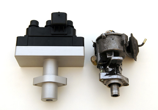
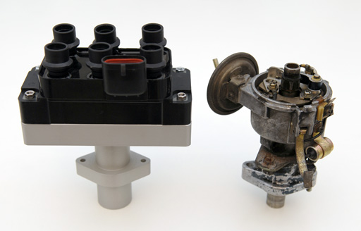
The top base is machined to carry the lower part of the coil pack, the lower pipe for the engine mount is hollowed out. Will post a picture as soon as it has been installed.
-
Took +4 weeks but i learned how to do technical drawings on the way... cnc machined out of a single aluminium billet, should be sturdy enough for things to come. Height is exactly as the original distributor including cap, so might look original enough to not draw attention to the conversion

-
Exactly, you put the tacho pickup loop inbetween the b/w wire supplying +12V and the coil (+) by doing this. The tach should work then (pressing thumbs). Good luck with the carbs!
-
Ok, you have identified the two missing wires for the tacho setup. Remove the wire currently supplying +12 Volt to the coil (+) terminal and connect it to the black/white wire with the female connector instead. Connect the (previously taped) green/white wire to coil (+) and your tacho should be active again! (if its plugged in ) Good luck, Adrian
-
O.L means the wires are not connected (infinitive resistance). Ok, now we need to check which of the two wire is not connected through the tach loop. Please disconnect the tacho connector from the tacho. The tacho connector has a green, green/white, black, and black/white wire. Measure the resistance by holding one probe to the (previously taped) green/white wire in the engine room and the other one to the tacho connector pin connected to the green/white wire. If you don't see O.L, then this is the correct green wire to connect to +12V from the ignition key. Repeat procedure for the black/white wire by holding one probe to the black/white wire with the female connector and the other one to the tacho connector pin with the black/white. If you don't see O.L, then this is the correct green wire to connect to the coil's (+) terminal. Good luck, Adrian
-
A very good friend indeed, Fluke makes quite nice equipment!
-
You can also use your test light: Make sure that the tacho is connector to the tacho, switch on the ignition power and 1. Connect the test light to ground and (taped) green, it should not light up (if it does, skip the other tests) 2. Connect the test light to ground and black/white, it should not light up (if it does, skip the other tests) 3. Connect black/white to ground. Connect one side of the test light to battery (+), the other side to the green wire -> the test light should light up 4. Remove the tacho connector from the tacho and repeat 3 -> the test light should not light up If 3. & 4. are positive, you have identified the tacho wiring
-
If you are a novice in the field of fuel injection and ECUs then you have quite a journey in front of you The distributor axle is in sync with the camshaft, so when you install a sensor on the distributor axle to indicate a specific point (first cylinder TDC as example) you can use this signal to tell your ECU about the phase. (Keep in mind that you need a rigid distributor axle, for a conversion of a standard distributor you need to remove the weights and weld the axle together at that point). Check the manual of your ECU to determine what kind of signal/angle is required for the cam phase identification, it was common to use a two teeth approach where one teeth was 90º or 180º before the TDC and the other on TDC.
-
You can always fit a Lumenition OptronicsOS50 pickup, or Pertronix Ignitor I to your (now unused) distributor, and remove all blades or magnets except the one to trigger on the first cylinder in the sequence (the exact configuration depends on what your ECU wants to see). This is how the engine phase was identified in the first fully electronic injection systems in the beginning of the eigthies, such as with the Marelli IAW based systems.
-
Hi Mike, the black/white wire connected to the coil with the black cable sleeve comes from the ignition key 'run' position, so the shorter black/white one with the female connector is most probably the one we are looking for! Here is a quick and simple test: put the meter in resistance mode and connect one probe to the green/white wire (currently taped) and the other one to the short black/white with the female connector. With the tacho connected you should see 0-2 Ohm. If you now disconnect the tacho connector behind the dashboard, you should see infinite (e.g. no) resistance. If thats the case you have identified both wires coming from the tacho loop! Let me know how this works out, then we can continue to wire up the tach.
-
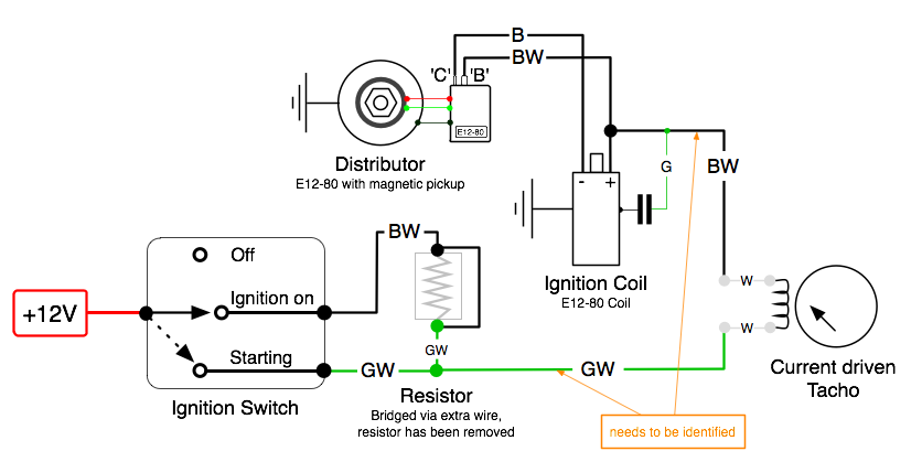
This is how your final wiring should look like
-
From what you have posted about the wiring, my assumption would be this: Green: was connected to Coil (+) and the capacitor (still connected to the capacitor?) Green/White: was connected to left side of the ballast resistor, comes from the ignition start position and one side of the white tacho loop Short Black/White with female connector: was connected to Coil (+), comes from the other side of the white tacho loop Longer Black/White: was connected to right side of ballast resistor, comes from ignition run position (should be in a black cable sleeve, is it?) Black: was connected to Coil (-), comes from the points/distributor. Still unsure about black/yellow, this is not on my '72 240Z and not in the later wiring sheets. You said that the Green/White wire has continuity with the Black/Yellow, so i suppose that the Black/Yellow is the same as the Black/White coming from the ignition key run position. Ok, now you need to identify the correct Black/White wire coming from the tach connector: Remove the connector from the tach and use the meter in Resistance/Ohm/Ω setting Connect one test lead to the Black/White wire in the connector and the other one to the short Black/White wire with the female connector, if this is the right one you should see 0-2 Ohm. If not check out the long Black/White wire instead. If you found the correct Black/White wire, then reconnect the tacho to the tacho connector and measure the Black/White wire in the engine compartment against ground. It should show the same voltage as the Green/White wire, about 12V if the ignition switch is in the run position, and no voltage, if the ignition switch is off. If so, then connect the Black/White wire you have just identified to Coil (+), instead of the current +12V supply wire. This should do the trick, you should now get +12V via the tacho loop to the coil and E12-80 ignition module.
-
I thought we are competing for the longest dialogue in a single topic thread on hybridz, no?