

vantage
-
Posts
104 -
Joined
-
Last visited
Content Type
Profiles
Forums
Blogs
Events
Gallery
Downloads
Store
Posts posted by vantage
-
-
When you say all over the place, does the needle bounces up to a higher RPM than the actual one, or does it bounce between zero and the actual RPM?
If it bounces between zero and the current RPM, then the tach signal is too weak, if it bounces all over the place there is something wrong with the duty cycle of the trigger signal (unlikely in your setup) or the signal is too strong and confuses the input stage of the tach. This should not happen with a tach adapter, though.
Turning on the parking lights does not change the cars voltage so much that it would have an effect, this sounds rather like a wiring problem or issue with the alternator/regulator. Could you measure the cars main voltage while idling and also when the tach stops functioning?
-
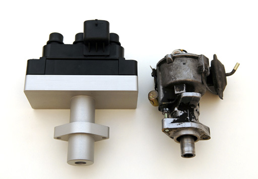
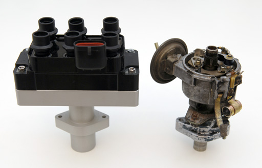
The top base is machined to carry the lower part of the coil pack, the lower pipe for the engine mount is hollowed out. Will post a picture as soon as it has been installed.
-
Some pics of the fancy new mount when it comes in are requested.
Took +4 weeks but i learned how to do technical drawings on the way... cnc machined out of a single aluminium billet, should be sturdy enough for things to come.
Height is exactly as the original distributor including cap, so might look original enough to not draw attention to the conversion

-
Exactly, you put the tacho pickup loop inbetween the b/w wire supplying +12V and the coil (+) by doing this. The tach should work then (pressing thumbs).
Good luck with the carbs!
-
Ok, you have identified the two missing wires for the tacho setup.
Remove the wire currently supplying +12 Volt to the coil (+) terminal and connect it to the black/white wire with the female connector instead.
Connect the (previously taped) green/white wire to coil (+) and your tacho should be active again! (if its plugged in
)Good luck,
Adrian
-
O.L means the wires are not connected (infinitive resistance). Ok, now we need to check which of the two wire is not connected through the tach loop.
Please disconnect the tacho connector from the tacho. The tacho connector has a green, green/white, black, and black/white wire.
- Measure the resistance by holding one probe to the (previously taped) green/white wire in the engine room and the other one to the tacho connector pin connected to the green/white wire. If you don't see O.L, then this is the correct green wire to connect to +12V from the ignition key.
- Repeat procedure for the black/white wire by holding one probe to the black/white wire with the female connector and the other one to the tacho connector pin with the black/white. If you don't see O.L, then this is the correct green wire to connect to the coil's (+) terminal.
Good luck,
Adrian
- Measure the resistance by holding one probe to the (previously taped) green/white wire in the engine room and the other one to the tacho connector pin connected to the green/white wire. If you don't see O.L, then this is the correct green wire to connect to +12V from the ignition key.
-
A very good friend indeed, Fluke makes quite nice equipment!
-
You can also use your test light:
Make sure that the tacho is connector to the tacho, switch on the ignition power and
1. Connect the test light to ground and (taped) green, it should not light up (if it does, skip the other tests)
2. Connect the test light to ground and black/white, it should not light up (if it does, skip the other tests)
3. Connect black/white to ground. Connect one side of the test light to battery (+), the other side to the green wire -> the test light should light up
4. Remove the tacho connector from the tacho and repeat 3 -> the test light should not light up
If 3. & 4. are positive, you have identified the tacho wiring
-
If you are a novice in the field of fuel injection and ECUs then you have quite a journey in front of you
The distributor axle is in sync with the camshaft, so when you install a sensor on the distributor axle to indicate a specific point (first cylinder TDC as example) you can use this signal to tell your ECU about the phase. (Keep in mind that you need a rigid distributor axle, for a conversion of a standard distributor you need to remove the weights and weld the axle together at that point).
Check the manual of your ECU to determine what kind of signal/angle is required for the cam phase identification, it was common to use a two teeth approach where one teeth was 90º or 180º before the TDC and the other on TDC.
-
Has anyone fitted a camshaft position sensor to an L Series engine?
My plan is to go fully sequential, I already have a trigger wheel fitted to my crankshaft and have LS1 Individual coil packs, just need to figure out the cam shaft sensor, so my ecu will know at what cycle the engine is in.
Advice, tips etc.. appreciated.
You can always fit a Lumenition OptronicsOS50 pickup, or Pertronix Ignitor I to your (now unused) distributor, and remove all blades or magnets except the one to trigger on the first cylinder in the sequence (the exact configuration depends on what your ECU wants to see). This is how the engine phase was identified in the first fully electronic injection systems in the beginning of the eigthies, such as with the Marelli IAW based systems.
-
Hi Mike,
the black/white wire connected to the coil with the black cable sleeve comes from the ignition key 'run' position, so the shorter black/white one with the female connector is most probably the one we are looking for!
Here is a quick and simple test: put the meter in resistance mode and connect one probe to the green/white wire (currently taped) and the other one to the short black/white with the female connector.
With the tacho connected you should see 0-2 Ohm. If you now disconnect the tacho connector behind the dashboard, you should see infinite (e.g. no) resistance.
If thats the case you have identified both wires coming from the tacho loop! Let me know how this works out, then we can continue to wire up the tach.
-
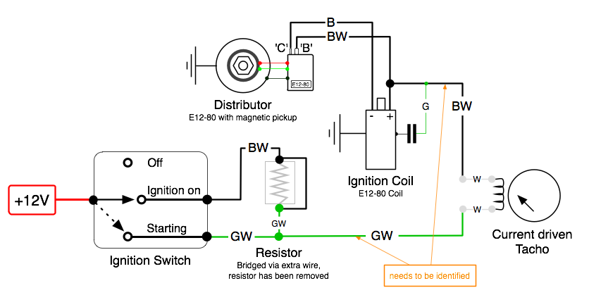
This is how your final wiring should look like
-
From what you have posted about the wiring, my assumption would be this:
- Green: was connected to Coil (+) and the capacitor (still connected to the capacitor?)
- Green/White: was connected to left side of the ballast resistor, comes from the ignition start position and one side of the white tacho loop
- Short Black/White with female connector: was connected to Coil (+), comes from the other side of the white tacho loop
- Longer Black/White: was connected to right side of ballast resistor, comes from ignition run position (should be in a black cable sleeve, is it?)
- Black: was connected to Coil (-), comes from the points/distributor.
Still unsure about black/yellow, this is not on my '72 240Z and not in the later wiring sheets.
You said that the Green/White wire has continuity with the Black/Yellow, so i suppose that the Black/Yellow is the same as the Black/White coming from the ignition key run position.
Ok, now you need to identify the correct Black/White wire coming from the tach connector:
- Remove the connector from the tach and use the meter in Resistance/Ohm/Ω setting
- Connect one test lead to the Black/White wire in the connector and the other one to the short Black/White wire with the female connector, if this is the right one you should see 0-2 Ohm. If not check out the long Black/White wire instead.
If you found the correct Black/White wire, then reconnect the tacho to the tacho connector and measure the Black/White wire in the engine compartment against ground. It should show the same voltage as the Green/White wire, about 12V if the ignition switch is in the run position, and no voltage, if the ignition switch is off.
If so, then connect the Black/White wire you have just identified to Coil (+), instead of the current +12V supply wire. This should do the trick, you should now get +12V via the tacho loop to the coil and E12-80 ignition module.
- Green: was connected to Coil (+) and the capacitor (still connected to the capacitor?)
-
I thought we are competing for the longest dialogue in a single topic thread on hybridz, no?
-
My car will start with the white connector unplugged. Bad news I guess. There is 11v between the black and the red/yellow. I never get 12v at any connection. Maybe my meter is off.
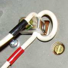
The white wire loop looks great. No corrosion or bent parts. I can't see anything wrong with it.
I think this is good news as your tach might still be functional
Voltage between black and red/yellow is good, so your tach receives power!- Measure the green/white wire on the connector to which the tach is connected and ground, do you see ~12V?
- Please check which wire color is connected to the Ignition coil (+) terminal (should be black/white)
- Also, is there an disconnected black/white or green/white wire next to the coil/ballast somewhere?
Regarding your meter, do you get 12,5V when you measure the battery while the engine is idling?
- Measure the green/white wire on the connector to which the tach is connected and ground, do you see ~12V?
-
Congrats, well done!
Distributor "one tooth off", that would have the same effect as being not properly set to the correct static timing. Your engine needs to settle in and the timing is not set yet, so no worries here.
Timing, 10º should be good. Let the engine warm up (stay below 2-2.5K), then set the timing to 10º using the strobe light. Do a test drive and also check if the engine pings on load but you should be good with that setting. Should be no problem to go up to 15º static advance with out the vacuum connected (i assume that you ignore the vacuum advance with your weber setup). Max advance should be 36º-38º at 2000-3000 RPM, you could check that with a variable timing light if you can borrow one.
I cant make out where the tube comes from in the photo but crankcase blowby sounds quite likely, the smoke should vanish after some hours of (gentle) driving when the engine has settled in again after the long rest.
Regarding the tach, you have a four wire tach where one side of the coil runs through a small loop at the back of the tach. So...
-
- When you remove the four pin connector from the tach, does the car still start? (It shouldnt) Then we need to take a look at the wiring.
- If the car does not start with the connector removed, the wiring appears to be correct. Then remove the tach and check out the white wire loop. It runs through a white piece of plastic which is fixed by a small metal clamp. Make sure that the small metal clamp is not bend and connects to the small metal counterpart on each side.
- While you at it, also make sure that you can measure +12V between the black and red/yellow wire at the back of the tach while connected to the car wiring and with the ignition on
-
-
sorry, i meant apply into both intakes of each carb
The starter feature ist not available in all DCOEs, it depends if you actually have the starter valve in the carbs installed by the factory, so dont worry about that. -
The carbs leak out the front. The kit does indeed have new needle valves. I'm going to look at the DCOE parts diagram and my Weber manual and try to figure out where all the parts in the kits go.
Today is the first time I've tried to start it since my last post. It was trying really hard to start. A couple of times it caught for a few seconds but I didn't give it throttle and I think I should have. Then a neighbor came over and turned the dizzy all the way CW (advanced?) and it wouldn't even try to start. I'm pretty sure the battery is going bad. The starter was turning much slower. The neighbor left and came back with a spark tester. He says it has weak orange spark. I'm hoping that is from the low battery.
Later...I had the battery charged at Autozone. When I went to pick it up they tested it and the machine read "battery good...low charge." The counterguy said that means it's going bad but maybe they just didn't leave it on the charger long enough. He was swamped with customers and had just one inexperienced helper so who knows. Maybe the battery has enough juice left to get the car started. I also had a battery in the garage that I bought new two years ago and never used. I dropped that one off to be charged when I picked the other one up.
BTW, before I tried to start the engine I turned the crank so that the balancer mark was closer to 10 than 5 and then turned the dizzy so that the rotor was facing the #1 point on the reluctor. I hope that was right.
A fresh or fully charged battery would be good, you want to have a strong spark and quick starter. With a mechanical fuel pump you need some rotations of the engine to prime the carbs, then when starting press the throttle a bit and keep it there. As the car was standing for so long, i would recommend to remove the air box and apply a bit of starter spray or brake cleaner into both carb intakes and try starting again. Make sure that the plugs are not wet from previous starting test.
good luck,
Adrian
-
Where does the DCOE's leak?
Might be a quick and easy start to remove the top cover and check out the following items before doing the next engine start:
- The floats (#9) do work (are not stuck or sticky) and are not punctured and filled with gas
- The needle valve (#8) is clean and functional (if your service kit contains new needle valves then just replace them)
http://www.webercarbsdirect.com/v/vspfiles/weber_carburetor_schematics/45DCOE152.pdf
-
Tony, thanks for tuning in!
Mike, looks good on the latest photo
Hmm, 3.0 psi are fine for the DCOE's. Have asked my Weber guy and he told me to check the float level and function, and to check and clean the needle valve. Not very likely if you have exactly the same issue on two carbs though but probably still worth a try. Take care you dont start a fire in the engine compartment. -
Difficult to say, i am not too familiar with the cam and valves of the L24. Which one is the intake and which one the exhaust valve? If the right one next to the chains is the exhaust valve then cyl #1 would be at the end of the power/burn phase (e.g. too late). If the left one is the exhaust valve, then cyl #1 would be shortly before the intake phase (e.g. too early).
In both cases it would not look be correcnt, the cyl #1 should be after the compression phase, e.g. both valves are closed. It might be helpful if you watch the cam openening/closing the valves while standing in front of the engine and slowly turning the crankshaft manually to see which cylinder is in the correct compression/burn phase while the balancer mark hits the degree marker.
-
Hmmm, your cams look like they are both up in the photo, e.g. both valves are closed which would be correct. How do the cams for cyl #6 look like?
If you are in a hurry to know
swap the wires on your dist cap by 180 degree and give it a try, worst thing that can happen is backfiring through the exhaust. -
Your distributor looks quite ok to me, good
lets recap- You verified that piston #1 at TDC is in alignment with the balancer TDC mark/degree plate
- You verified that the TDC mark/degree plate is in alignment with the rotor pointing to HV cylinder #1 terminal
That leaves the spark wires and the timing. Guess that the spark wire aligment is good, so would recommend to turn the distributor clockwise all the way to fully retard the timing.
If the engine wont start now, turn the distributor 1/3 of the way CCW to advance it a bit and try again. If you get a backfire, you might want to try out the approach with just the first spark wire from above.
Good luck,
Adrian
-
The car ran great before so I assume it was right and still is. As in, the cam gear is correct, the crank gear and balancer are correct, and the oil pump is correct. Nothing has been changed in the engine itself.
It's just my understanding that when the crank mark lines up at 0 degrees, the engine is at TDC and the rotor should be facing #1 on the dizzy. Is that incorrect?
Correct, and if the car ran before then it is indeed quite unlikely that the piston #1 is not in sync with the crank mark line.
Just something i noticed when looking at your dist in the photo: the rotor does not seem to be exactly 180 degrees opposite of cylinder #1 but almost pointing to the next cylinder (which would explain the starting problems). Thats why i was interested where the rotor points to when you turn the engine manually to the TDC mark/0 degree.
Converting a current driven tacho into an electronic tacho
in Ignition and Electrical
Posted
I've updated the project to a full tacho circuit board replacement, so you don't need to have a programmer and software anymore to build this. The project is using the same link:
http://www.dinoplex....achoconversion/
enjoy,
Adrian