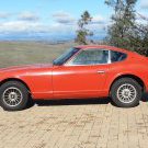
280Z-LS3 Posted June 15, 2020 Share Posted June 15, 2020 (edited) First off would like to say I would never have had the knowledge nor courage to tackle this build without HybridZ and its awesome community so willing to offer advice and share ideas. Purchased my running 1975 280Z almost rust free San Diego area car about 4 years ago with the intent to start the build sooner. With getting two girls off to college then moving to a new home, which included renting for a year while finding the "right" property, let's say the car hobby took a back seat. Sacrilege! The silver lining is all this time afforded plenty of lurking here, other Z sites and Ls1Tech reading, learning, planning then changing the plan a few times. Finally settled on a build which I will get into now. Engine I knew I wanted an LS3 motor because it's powerful, compact, well supported by aftermarket, and affordable. Grabbed a 2008 Corvette LS3 complete pullout. With cam and headers upgrade 450+ rwhp is easy, more than enough for a 2600 lb car being built for the canyons, Autocross and track days. Transmission The F-Body 98-02 T-56 fits the S-30 chassis well, shifter lines up in stock trans tunnel hole almost perfectly. However, these are hard to find and expensive on used market so choosing a new Magnum-F, touted as "direct" replacement for F-Body, makes sense. For the added cost of new over used, you get brand new never beaten on trans with better internals capable of handling more torque and improved shifting. This is a major purchase line item so have been it putting off as long as possible. Time is growing near to get it into the garage... Rear Differential Although my 1995 Z has a stout-as-hell R200, the rest of the stock rear is a mess needing expensive upgrades to handle LS3 torque. A few Mustang 8.8 swap came and went over the years then Vlad, AKA Invincible Extremes, came out with his 2015 Mustang Super 8.8 swap. Watched the whole development thread then pulled the trigger, boom! Insane power handling with easily sourced parts. Ordered up Vlad's "tack welded" kit with his custom axles, purchased an 8.8 Torsen limited slip 3.73 gear diff and some new hubs. Done. Bring on the HP... Suspension Vlad introduced me to Noah (Instagram: @noahdropkin), a young talented mechanical engineer, when I had in depth technical questions about the 2014 Mustang spindle swap. Noah had the 2014 spindle swap at the time and also has the Super 8.8 swap. His main reason for interest in the 2014 swap, as well as mine, was it gave a cheap and strong 5 lug hub to match the rear 5 lug hub of 8.8 swap. There are a few compromises with the 2014 spindle that we discussed at length. Over the course of a few weeks of discussions, Noah decided to grab a 2015 spindle to explore its possibility for swap. Doing some magic with a digital scanner and Solid Works he concluded this could actually work, with some custom parts of course... Hot Damn!!! Noah started in on the heaving lifting of computer modeling and fabrication, he truly is the brains and brawn behind all this, while I peppered him with questions during design phase. When Noah committed to building a swap kit for his car he asked if I would like one also. Ah, Hell Yeah! Noah has test fit the kit posting plenty of good pics on his Instagram page. The end result is the wheel base remains stock, slightly wider tract width, improved scrub radius, good camber and minimal effect on Ackerman. Steering ratio increases due to the shorter steering arms on the 2015 spindle. For Noah's 240 steering rack, the resulting steering ratio is a snappy 10:1 while with my 280 steering rack is close to 11.5:1, a bit more tame but still fast. Off the shelf coil overs are available for Vlad's front and rear swap but Noah and I agreed that good dampeners are in order. Custom strut tubes were fabricated for the Koni 8611-1259 dampeners, arguably the best off the shelf dual adjustable dampeners for S-30 chassis. More details to follow as I dig into this build now that the major parts are here to play with. The last pic is 2015 Mustang with swap concept drawn. Edited June 15, 2020 by jsulse 1 Quote Link to comment Share on other sites More sharing options...
280Z-LS3 Posted June 21, 2020 Author Share Posted June 21, 2020 Tear down begins. Engine/trans drained and pulled out. Fuel system and interior next. Quote Link to comment Share on other sites More sharing options...
DonH Posted June 25, 2020 Share Posted June 25, 2020 dude... I need more info on the 8.8 rear end!!!! Quote Link to comment Share on other sites More sharing options...
280Z-LS3 Posted June 25, 2020 Author Share Posted June 25, 2020 All info you need for Super 8.8 swap Quote Link to comment Share on other sites More sharing options...
280Z-LS3 Posted June 26, 2020 Author Share Posted June 26, 2020 Can anyone offer advice on using an aftermarket body wiring harness? My 76 280Z EFI has an incredible amount of wiring on the passenger kick panel that is going to make fitting roll cage, engine ecu, etc difficult if not impossible. Quote Link to comment Share on other sites More sharing options...
Invincibleextremes Posted June 29, 2020 Share Posted June 29, 2020 It's exciting to see noah and you actually bolt together the front spindle swap using the double ball joints. That's definitely something new, and gives you one generation of donor parts for your car front and back. Quote Link to comment Share on other sites More sharing options...
Wildfire490 Posted June 29, 2020 Share Posted June 29, 2020 On 6/26/2020 at 9:14 AM, 280Z-LS3 said: Can anyone offer advice on using an aftermarket body wiring harness? My 76 280Z EFI has an incredible amount of wiring on the passenger kick panel that is going to make fitting roll cage, engine ecu, etc difficult if not impossible. https://forums.hybridz.org/topic/131462-78-280z-lt1t56-project/ I'm installing painless body and fuel injection harness' in my 280Z. I mounted the body harness fuse block on the driver side near where the stock Datsun computer was. I'm going to mount the LT1 computer and fuse block on the passenger side near where the Datsun fuse block was. I have some pictures of my progress so far in my thread. If you have any questions, feel free to ask Quote Link to comment Share on other sites More sharing options...
280Z-LS3 Posted July 8, 2020 Author Share Posted July 8, 2020 A small update. Finished the the boring tear down. Ziplock bagging all the parts, removing mastic sheet sound deadener and cleaning remaining mastic residue with Mineral spirits. The windshield seal became brittle over the years and needed to dug out with razor knife, not fun. The is body free of rust as I hoped except for the known areas, passenger door and passenger fire wall. Seems the car was exposed to a sprinkler or something in the passenger side for a time. My last build was a Mustang, see pic, and didn’t want to relive that experience so waited to find a body on good shape. I have a replacement passenger door which has some repaired collision damage. Going to strip the door, remove the collision bar so I can weld up drill holes used to pull the door skin and hammer it out to minimize bondo. Will remove the drivers door collision bar also. Installing a full cage so they would be redundant anyway. I toyed with the idea of using the spare door as a donor for the rusted area of the original door but the location And extent of the rust damage would make that job very complex. I can live with the bondo on the panel. Quote Link to comment Share on other sites More sharing options...
Richard Oben Posted July 10, 2020 Share Posted July 10, 2020 That is a lot of work yet to be done. But, starting from scratch is the best way to get it all correct, and the way you want it. So now the only question is blast or not to reveal anything hidden. Great work!! Quote Link to comment Share on other sites More sharing options...
280Z-LS3 Posted July 10, 2020 Author Share Posted July 10, 2020 Don't think I am going to blast the body Richard. Other than the door and firewall there is minimal rust. That will save me some money I can put to other things. Next step is the Bad Dog frame connectors. While I'm prepping for the rails will poke around with the sander and screw driver just to make sure there are no hidden patches of rust. Quote Link to comment Share on other sites More sharing options...
280Z-LS3 Posted July 15, 2020 Author Share Posted July 15, 2020 My DIY rotisserie which I call “The Abomination” is a flawed design cobbled together from scrap oil field pipe and tubing lying around the ranch. It functions but had two glitches, no adjustment to move center of gravity toward rotational axis Making it very difficult to spin and the sliders would bind not allowing car to be lowered without a BFH. So decided to improve the design. Quote Link to comment Share on other sites More sharing options...
280Z-LS3 Posted July 15, 2020 Author Share Posted July 15, 2020 Some car parts arrived today! Needed a seat and seat belt harness so I can start designing and fitting roll cage. Pulled the trigger on a Cobra Suzuka and Schroth Flexi Hans compatible harness. Quote Link to comment Share on other sites More sharing options...
280Z-LS3 Posted July 20, 2020 Author Share Posted July 20, 2020 Decided to make a tubing bender floor mount and heavily duty steel table after modifying the rotisserie. The top of the table will be welded on after installing casters which arrive in mail tomorrow. Started prepping for the sub-frame connectors. Quote Link to comment Share on other sites More sharing options...
280Z-LS3 Posted August 3, 2020 Author Share Posted August 3, 2020 A little up date. I have many irons in the fire, kind of jumping around. Still cleaning up the under side of car to install frame connectors and spot weld sheet metal seams. This will be a long and tiresome job so maybe that's why I keep moving around, lol. Used a ball carbine bit to grind away the spot welds on trans mount tabs. Name your poison on this job, angle grinder with flying sparks and almost uncontrollable material removal or the carbide which produces millions of little sharp needles that get stuck in my hands no matter how careful to avoid. Decided I had to be different and commit to using a SD7 mini A/C compressor mounted at driver's head. No aftermarket company makes this arrangement except John's Cars but he utilizes an SD5 with F-Body belt spacing and I have Corvette spacing. So custom mount it is. Hoped that some generic mount plates would work but they don't have enough material to cover face of head for bolt holes. Made some plates and now just need to drill some holes, cut away excess material and maybe even add a few large holes to lighten plates. Will fabricate spacers to locate belt 99mm to 100mm from face of head, that's what I measured with OEM alt mounted and worn belt that came with engine. For the re-located Alt I went with a 2006 Cadillac CTS-V 140 amp and bracket that has Corvette spacing. The bolt on the lower left will be used to mount a smooth pulley to add belt wrap around crank and alt pulleys. Almost finished welding up the 8.8 cradle and knuckles. Going to test fit kit so I can weld poly mount tabs and also check fitment for fabricating the rear subframe connector to tie the Bad Dog frame rails to the rear cross member that lower a-arms attach. Doing this to avoid clearance issues which I don't expect but you never know... Oh, waiting on the Techno Toy Tuning arms too so will hold off till they arrive, this week hopefully, so I can mock up the entire rear while at it. Have not spec'd the brake calipers yet so leaving the Mustang tabs tacked in case I need to fab new ones. Quote Link to comment Share on other sites More sharing options...
ShawnM Posted August 16, 2020 Share Posted August 16, 2020 That A/C bracket and diff carrier both look like stout pieces. Nice work. Quote Link to comment Share on other sites More sharing options...
280Z-LS3 Posted September 11, 2020 Author Share Posted September 11, 2020 Finally completed cleaning up the chassis by removing undercoating, seam sealer, glue, etc. That was a long and crappy job! Thinking I am going to get the engine/trans mounted before tackling the seam welding and roll cage because of my idea for trans mount. I would like the trans to bolt to the Bad Dog frame rails with blind nuts, nuts welded to the inside of frame rails. I also removed the spare tire well and miscellaneous brackets in the engine bay that will not be of use. While trying to keep from going insane with undercoating removal I broke off to make a press brake for my cheap HF 20 ton press and some sub-frame connectors templates. The press brake is to bend up some 3"x5/16" steel bar for transmission mount. Transferred connector shapes to 12 gauge sheet metal and just need to be cut out and bent up. I am pretty certain these will clear the rear roll bar. As of now I don't plan on using a rear bar but though it would be nice to retain the use. Gathering some material for a DIY 4' sheet metal brake to form the connectors and maybe a custom center console and dash in the future. Quote Link to comment Share on other sites More sharing options...
280Z-LS3 Posted October 1, 2020 Author Share Posted October 1, 2020 Time for a update! Test fit the 8.8 diff. Engine/trans going in next. Should have them in by end of today. I also leveled the body on jack stands by using the frame rails as point of reference both side to side and front to back. Notice I have cut the engine mount towers off cross member making room for DIY puck style engine mounts. I needed to determine chassis center line for both engine placement and welding in camber plates square to car center line. If the camber plates are not square caster will change when camber is adjusted. Pulled mason line across three points, front of frame rails, back of frame rails near fire wall and between mustache bar mount studs and wrote with marker center of each point of each line. Then pulled mason line front to back both under car and through cabin using plumb line to locate using the three reference line points. Marked where mason lines touched the chassis with marker so can easily be removed and re-install as needed and also to have reference points to refer to when engine/trans is installed interfering with line installation. Quote Link to comment Share on other sites More sharing options...
280Z-LS3 Posted October 3, 2020 Author Share Posted October 3, 2020 Test fit LS3 motor and F-Body Magnum trans. Played with different engine tilt angles and seems 1.5-2.5 degrees rearward gives best placement. Any more angle such as 3 degrees allows for more harmonic balancer/steering rack clearance at the expense of extending rear of oil pan and bell housing below frame rails. I pulled lines across frame rails and from cross member to check oil pan and bell housing clearance, to see if they hung below frame rails or cross member. The limiting factor of getting the engine as close to the firewall as possible is the vacuum hose at back of intake manifold. I was able to achieve 4cm/1.5" from block/trans face to firewall and the center line of crank approximately 1cm below top of frame rails. Could possibly go lower after I install an ATI 10% underdrive harmonic balancer and pulley having about 3/4" small diameter than OEM netting about 3/8" more clearance. How do these measurements compare to other LS swaps? Keeping trans tail shaft on chassis center line offsets the F-Body Magnum shifter to the driver's side of tunnel hole. Notice in photo above the shifter housing is offset to driver's side. If this shifter location becomes bothersome will fab up a spacer to center stick more to the right. Looks like I will need to clearance the tunnel hole so the shifter boot does not get chewed up. Also purchased from EBay a mechanical reverse lockout to replace the massive solenoid type. Waiting on three things to complete drive line placement ATI dampener, dry sump oil pan and Ford Super 8.8 pinion nut (not re-usable) which is a dealer only item part #FL3Z-4320-A for swapping the Mustang pinion yoke to Yukon YY F100603 which utilized 1350 u-joint. I was going to modify the LS3 pan by adding 2 scavenge bungs but seriously considering just getting a good dry sump pan, either ARE 1005M or 1005S. Waiting for parts to arrive I pulled rear diff and motor/trans and have begun the stitch welding of sheet metal seams. Quote Link to comment Share on other sites More sharing options...
280Z-LS3 Posted October 3, 2020 Author Share Posted October 3, 2020 (edited) Oh, here is a pic of engine/trans assembly. Working alone required some creativity with milk crates and scrap lumber getting trans into place, it is one heavy MOFO! Edited October 3, 2020 by 280Z-LS3 Quote Link to comment Share on other sites More sharing options...
280Z-LS3 Posted October 8, 2020 Author Share Posted October 8, 2020 Seam stitching progress. Tedious process getting paint and seam sealer out of seams but it's better get good and clean than having to deal with contaminated welds. I have not found a trick to get-er-dun quickly. A small flat head screw driver turned out to be the best for tight corners and the pointed body hammer helped close some wide gaps before welding. To help keep burning paint and seam sealer smoke from welding out of my face and lungs, even with respirator, I picked up a 6"x25" hood vent duct from hardware store and attached to bullet fan to draw away smoke. The hose end is held in place by a powerful magnet allowing for ease of movement and sturdy location. The magnet was one of those impulse buys, "gotta have it but don't know what I'll ever use it for", which finally found purpose. Quote Link to comment Share on other sites More sharing options...
Recommended Posts
Join the conversation
You can post now and register later. If you have an account, sign in now to post with your account.