clarkspeed Posted June 4, 2021 Author Share Posted June 4, 2021 Wow I missed out on posts for the last couple days. Some interesting techniques I need to try out. I tend to use very thin sheet to fill body panels, sometimes even thinner than the Datsun panels. No gap, low heat, and typically a "pearl necklace" finish like you mentioned. Although I would never use that phrase. I always check the back side for overall good pen, but not every mm, grind to finish, and then thin bondo along with a backside coating. I rarely hammer the welds or shrink metal, just smallest negative profile I can attain (less than 1/8"). Small pinholes everywhere. But keep in mind, I build race cars, not show cars, so I'm not to concerned about getting an all metal flat finish like the guys do on TV. As long as I can duplicate the contour, no one will ever check it with a magnet. Race cars always stay indoors, and tend to be repainted often. I've never had a bondo crack or rust break through, without direct contact of course , Quote Link to comment Share on other sites More sharing options...
AydinZ71 Posted June 4, 2021 Share Posted June 4, 2021 @clarkspeed respect I have been bogged down for almost a year on rust repair, so I have had a huge amount of practice. Totally agree with you that it doesn’t matter on a race car. Sorry for hijacking your own thread by the way!! My work is a combination of structural and non-structural since rust has no bounds. Very excited to see how you progress! Quote Link to comment Share on other sites More sharing options...
clarkspeed Posted June 5, 2021 Author Share Posted June 5, 2021 I have been using these Mazda throttle body flanges for brake cooling ducts. I found them on amazon super cheap. They are cast aluminum and I just drill them to fit the holes for the OEM backing plates. Quote Link to comment Share on other sites More sharing options...
clarkspeed Posted June 5, 2021 Author Share Posted June 5, 2021 Here is my rear control arm design I lifted from this forum. Using the original arms saves much weight. You can also see where I raised the cross beam clearance and added support to the dog bone uprights. Quote Link to comment Share on other sites More sharing options...
AydinZ71 Posted June 5, 2021 Share Posted June 5, 2021 @clarkspeed looking good! I didn’t realize a modified lower CA would be cheaper than aftermarket? AE claimed theirs are 3.5lbs lighter than OEM 🤷🏽♂️ I will weight then this weekend and get some data. Still, I think the mod to the OEM unit works and looks great! I also was unaware the rear LCA vertical supports needed reinforcing. I will have to look at that! They flex much? I have my sway bar mounted to them so maybe that will add some rigidity. why did you north the crossmember above the diff? Had clearance issues? I’m thinking if notching the front LCA crossmember so I can build-in some adjustability on the front diff mount. Quote Link to comment Share on other sites More sharing options...
clarkspeed Posted June 6, 2021 Author Share Posted June 6, 2021 Lots of info on this forum on the doggone support. On other cars I have tied it into a bushing on the mustache bar studs. I WAS planning to run my R200 diff raised slightly to get level halfshafts after lowering and keep the u-joints. Another cheap, light, reliable, and effective solution. But now I am considering the Ford 8.8. I saw Tube80 post this control arm years ago and could not resist copying. Such a simple solution, but just a little heavier that stock. Something lighter than that formed steel stock arm that includes adjustment would be an accomplishment. Quote Link to comment Share on other sites More sharing options...
clarkspeed Posted June 12, 2021 Author Share Posted June 12, 2021 At some point I built this rotisserie. It saved an unbelievable amount of time with this project. Quote Link to comment Share on other sites More sharing options...
clarkspeed Posted June 12, 2021 Author Share Posted June 12, 2021 Here are some details of my rear suspension redesign. My goals were using the modified rear control arms I already had and having an adjustable roll center in the rear. I never liked the idea of welding or bolting on another tube at the bottom of the strut to drop the outer pivot bolt lower. And my rear control arms had the restriction of the 1" tubing inner pivot. After a lot of thinking, I came up with these Delrin bearing holders that raise the inboard roll center about 0.7" . I can shim them down if I want to reduce it. Light weight, low friction. This also eliminates the big ass bolts with a fore/aft brace that keeps the bearings centered. I think I am going to change them to something a little beefier in the future. As you can see, raising the inner pivots quickly jams the control arm up into the tub. So I cut out some clearance holes and added another brace there. Quote Link to comment Share on other sites More sharing options...
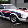
clarkspeed Posted June 12, 2021 Author Share Posted June 12, 2021 This is the body kit I have decided to build around. I had a full 5 piece IMSA GTU bubble fender wide body set and sold it when I found this G-nose based kit. I bought it off a guy in Tampa and I have no idea where it came from or how old it is. I have never seen another one like it. I came with 4 fenders, G-Nose, cowl induction hood, and whale tale spoiler. Not the best gel coat finish, but I can work with it. I like it because it widens the fenders out exactly 2 inches all the way around. Very subtle. No wasted drag. And I intend to run 15x10 wheels square, so perfect fit. I am convinced I can get some gains out of 15" wheels/tires as opposed to the 16x10 and 16x12 setups common for this type of build. They are mounted using 1/4 turn fasteners for fast removal. You can see a 15x9 inch wheel fit up. Quote Link to comment Share on other sites More sharing options...
AydinZ71 Posted June 13, 2021 Share Posted June 13, 2021 @clarkspeed looking good, Clark! I have seen a few folks on here say the friction from PU bushings adds an undesirable static friction to the CA’s (and suspension) travel. Is that why you went Delrin? In my experience, delrin work-hardens so you might end up with a little bit of slop over time. Your bushing is pretty long though so the cross-axial forces should zero out the slop. Good luck, and let us know how she feels!! I am finally making my way to the front suspension and trying to decide between modifying my own adjustable LCA’s or buying them from these bolt-on dudes. My only reason would be to save time. Ok already bogged down on sheet metal replacement. Quote Link to comment Share on other sites More sharing options...
clarkspeed Posted June 15, 2021 Author Share Posted June 15, 2021 I keep a close eye on suspension anyway. I made them fairly tight so they need to loosen some. For front LCA's it depends on what you need. If you have camber plates you dont really need adjust at the arm. And I normally use a wheel spacer to adjust track. Personally I just pop a spherical bearing in a stock arm and slot the cross member vertically about 1/8-1/4 inch to adjust out bump steer. (You can cover that with a washer if needed!) The only reason I built for this car is I replaced the t/c mount with a rod end in the exact same location. Quote Link to comment Share on other sites More sharing options...
clarkspeed Posted July 13, 2021 Author Share Posted July 13, 2021 And here are some pics of the exhaust. To keep ground clearance I needed to wrap the exhaust around the transmission and it will exit on the passenger side rocker panel. I took a standard 6 into 2 header and fabbed a some turns and a collector. A couple of v-band clamps allow removal of the entire system. At some point in the future I need so sandblast this thing and coat it. Quote Link to comment Share on other sites More sharing options...
clarkspeed Posted July 13, 2021 Author Share Posted July 13, 2021 This is the strut tower brace I fabbed. It is made from something like .060 steel square so it is very light. That is why I added so many gussets and triangles. It seems very rigid. It will be hard bolted to towers and roll cage. Quote Link to comment Share on other sites More sharing options...
AydinZ71 Posted July 14, 2021 Share Posted July 14, 2021 Very cool brace lots of work! fascinating solution on your exhaust! I assume you went over vs. under because of ground clearance. Never seen that before. How much longer do you think you have before she is ready for prime time? Quote Link to comment Share on other sites More sharing options...
tube80z Posted July 15, 2021 Share Posted July 15, 2021 Awesome job on the exhaust, well awesome job all around! Those headers were pretty common on all the tubeframe cars running hear in the northwest. They get very hot in the car so you'll want a lot of shielding. You might be able to vent some air from the cowl into the fabbed transmission tunnel to help cool it down. Quote Link to comment Share on other sites More sharing options...
clarkspeed Posted July 15, 2021 Author Share Posted July 15, 2021 21 hours ago, tube80z said: Awesome job on the exhaust, well awesome job all around! Those headers were pretty common on all the tubeframe cars running hear in the northwest. They get very hot in the car so you'll want a lot of shielding. You might be able to vent some air from the cowl into the fabbed transmission tunnel to help cool it down. Thanks for the kind words. It will have a straight shot of air down the tunnel to keep it cool AND I plan to add plenty of insulation to the surrounding panels. Yes this is a common technique used by tube frame GT cars. The car will have a flat bottom and I will try to squish that down as much as possible. I have used oval exhaust tubing in the past, but that didn't seem feasible for this build. Quote Link to comment Share on other sites More sharing options...
clarkspeed Posted July 28, 2021 Author Share Posted July 28, 2021 Here are some details of the differential mount. First I raised the stock cross beam to add some room because I think will need some space to raise the differential. Goal here is to keep the axles close parallel to reduce stress. If you can keep them relatively parallel during operation, the stock half shafts along with some good u-joints can handle just about anything a NA L6 can throw at them, therefore saving me some money over a CV conversion. Next I cut some metal out of the dog bone cross link to have better access to the oil change plugs. I added a brace to compensate. Then I used a cut up stock lower front diff mount to mate with the front cross member I am using. It will be hard bolted using the stock long diff bolts. Then last I built an adapter plate that bolts to the moustache bar and raises the diff up 1.9". I don't think I need that kind of lift, but if I add it in, I can bring it back down with some shims on the mustache bar mounts. The mustache bar will be also hard mounted to the stock studs with a rigid bushing. Quote Link to comment Share on other sites More sharing options...
clarkspeed Posted July 28, 2021 Author Share Posted July 28, 2021 More ass end work. I originally bought this 1" light weight hollow sway bar to mount in the front and not run a rear bar. That is normally how I build a Z up with basic unibody. But after thinking about it, I think this partial tube chassis will be rigid enough to go a different direction. So I decided to run slightly lighter springs with stronger sway bars both front and rear. So I moved this bar to the rear and will purchase a heavier bar for the front once I do all the math to calculate what size it will need to be. For the rear I purchased some weldable arm kits from Speedway Motors. I also built a bearing holder and used the 3D printed Delrin bearings I already have. 1/2" rod ends and clevis bolted to the control arm in the original location. Quote Link to comment Share on other sites More sharing options...
AydinZ71 Posted July 28, 2021 Share Posted July 28, 2021 I have always wanted to know how a car felt between the two options: heavy springs with no rear sway bar vs. light springs with a rear sway bar. Let ya know how you like it! Quote Link to comment Share on other sites More sharing options...
clarkspeed Posted July 30, 2021 Author Share Posted July 30, 2021 On 7/27/2021 at 11:40 PM, AydinZ71 said: I have always wanted to know how a car felt between the two options: heavy springs with no rear sway bar vs. light springs with a rear sway bar. Let ya know how you like it! I wish I could tell which was fastest. The S30 Z really likes no bar on the rear. That is how Greg runs but in grippy turns he is always lifting a front wheel. The books will tell you that is traction lost, but you are making it up with sooner throttle..... so it depends. I think my chassis is stiff enough to treat it more like a full tube car. If you run without a rear bar, you just need to reduce the stiffness of the front bar accordingly, regardless of coil spring stiffness. Quote Link to comment Share on other sites More sharing options...
Recommended Posts
Join the conversation
You can post now and register later. If you have an account, sign in now to post with your account.