

scott
-
Posts
37 -
Joined
-
Last visited
-
Days Won
1
Content Type
Profiles
Forums
Blogs
Events
Gallery
Downloads
Store
Posts posted by scott
-
-
Is there any place that sells or rebuilds 280zx turbo CV axles that actually fit and are decent quality?
-
I had a similar problem with my dual electric fan set-up driving at lower speed around town. The fans were rated at a good airflow, but it turns out this was at free flow (no back pressure). The fan curve for these low cost fans showed that the flow rate dropped off dramatically with just a little back pressure. My 240z has a lot of back pressure in the engine compartment (poor airflow out). I replaced electric fan with a more powerful Spal fan that has a better fan curve. It solved my problem.
-
I have that air dam on my 73 and I used a large metal file and easily removed material. I was also able to bevel the edge of air dam inward for more clearance. The file was easy to control the amount taken off. I did this with tires mounted and car sitting on ground and the air dam was already painted...no problem
-
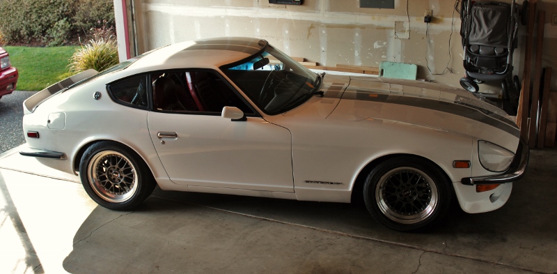
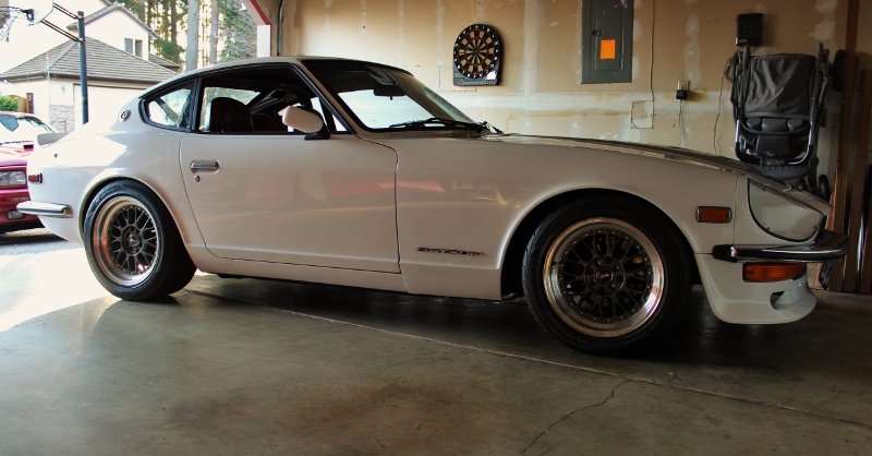
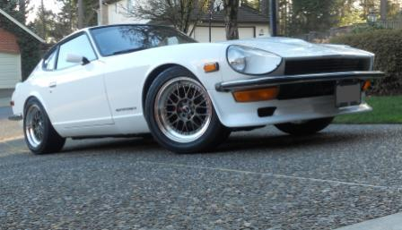
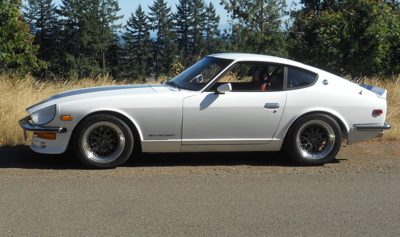
Here's my 240 with T3 coilovers and Konis

-
 2
2
-
-
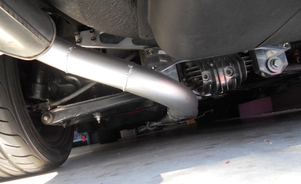
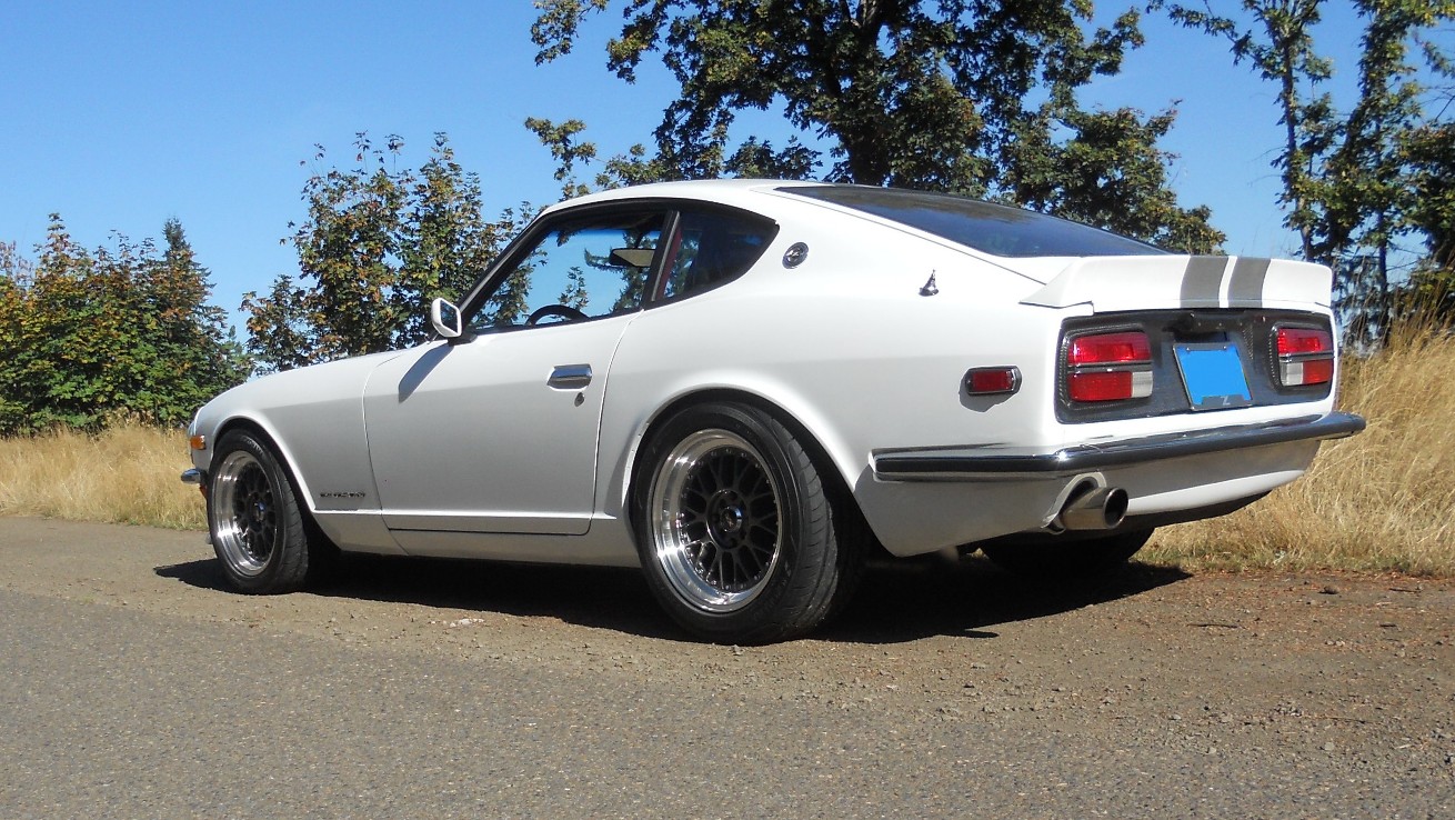
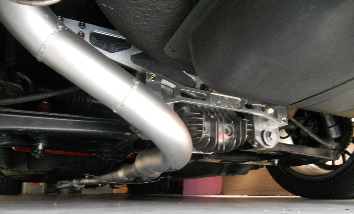
Two 2.25" exhaust merged into single 3" with 3" Turbo Muffler
-
Nigel, thanks!!!! The link has the exact parts I'm trying to find. Heavy85, I agree. I am checking suspension travel and steering turning range. Looks like I have enough brake line. Thanks for the input.
-
I would like to attach my stainless flex front brake lines directly to my calipers. Both the calipers and the flex line have M10 x 1.0 female threads. Normally there is a small section of hard line that connects to the caliper then to the flex line. The joint between the flex line and the hard line is held in place with a bracket on the strut. On my coil overs I do not have the bracket and so would like to attach the flex line directly to the caliper.
Ideally, I would like to find a M10 x1.0 male to M10 x 1.0 male adapter to directly connect the flex line. Does anyone know where to find one? What have you done to connect flex line directly to the caliper?
-
Because there are several factors beside the brake components themselves that affect braking distance, setting up a test with one car and running tests with various brake configurations could separate out some of the variables. The test car could have a base configuration (weight and weight distribution) and set up with wheels (that can fit various brake components) and good tires (so that limits of some brake configurations can be evaluated). Similar brake pads could be used, but there are trade-offs (initial braking distance, fade, rotor wear. Some are better for track use and others for the street)
This could be done like component evaluations done in some of the performance car magazines, like intake manifold evaluations or carburetor comparisons done on a base engine.
Other factors should be evaluated like brake fade, reliability (this could be harder to evaluate), weight and cost (most are looking for a good balance of features for their braking system).
I'd be interested in seeing this. I would like to see how Toyota SW12 calipers with 300ZX vented rotors compare with the stock brakes and with a Wilwood set up, etc.
-
One of the challenges with cooling in a 240Z or 260Z is getting rid of the heat and air trapped inside the engine compartment (hood louvers or 280Z vented hoods can help). The airflow into the engine compartment creates backpressure on the fan. A fan with a 2500cfm rating is moving that air at zero back pressure. As back pressure builds, the fan airflow drops off dramatically (check out some fan curves). It takes a fan with a strong motor to keep good airflow (cfm) with backpressure created in the engine compartment, usually a fan with 20+ amps. The Taurus fans can pull around 35 amps.
I am experiencing a similar problem on my two fan set-up. The fans aren't very strong and don't move enough air on hot days in stop and go traffic (they look good though). I don't have a vented hood, so the engine compartment builds some backpressure and traps heat. It is in traffic, traveling at low speed that the fans get the most workout. At highway speeds, the air is being rammed through the radiator, so cooling system capacity is now the important factor.
My little fans were rated at around 8 amps, so they are not strong enough. I am now looking for more powerful fans.
-
Checkered Flag Racing has adapters for the 280ZXT axles and also for the Z31 axles
-
Trimming the air dam isn't that big a problem, I had to cut quite a bit of it to get it to fit properly around the custom bumper and tow hook. I would just be bummed out to have to trim it now because I just plastidipped it and it's looking so clean! Oh well, it's the price we pay for nice wheels. What 16's do you have Scott? Can you share some pics please?
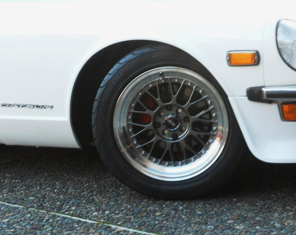
I had to trim mine after it was painted, but by using a file on the urethane and chamfering it inward, it did not show or chip the paint. I am running some XXR521 which are +20 offset, but I use some spacers (19mm in front and 11mm in rear) to space wheels and tires (225 50 16 yokohama) for best clearance.
-
415DZ, I have a Xenon front spoiler on my 240Z with 225 50 16 tires and 16 x 8 wheels with a +1mm offset. The car is lowered about 1.5". I had to trim the inner flange where the air dam bolts to the fender. I had to grind back the edge on the air dam and flange about 45 degrees from the wheel opening. I did this while the air dam was installed. I also used a file to grind away a small amount of the air dam bottom edge at the wheel opening for more clearance (Chamfering the edge inward).
This is easy to do even after the air dam and wheels and tires are installed.
-
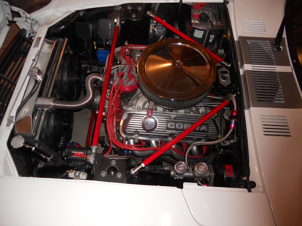
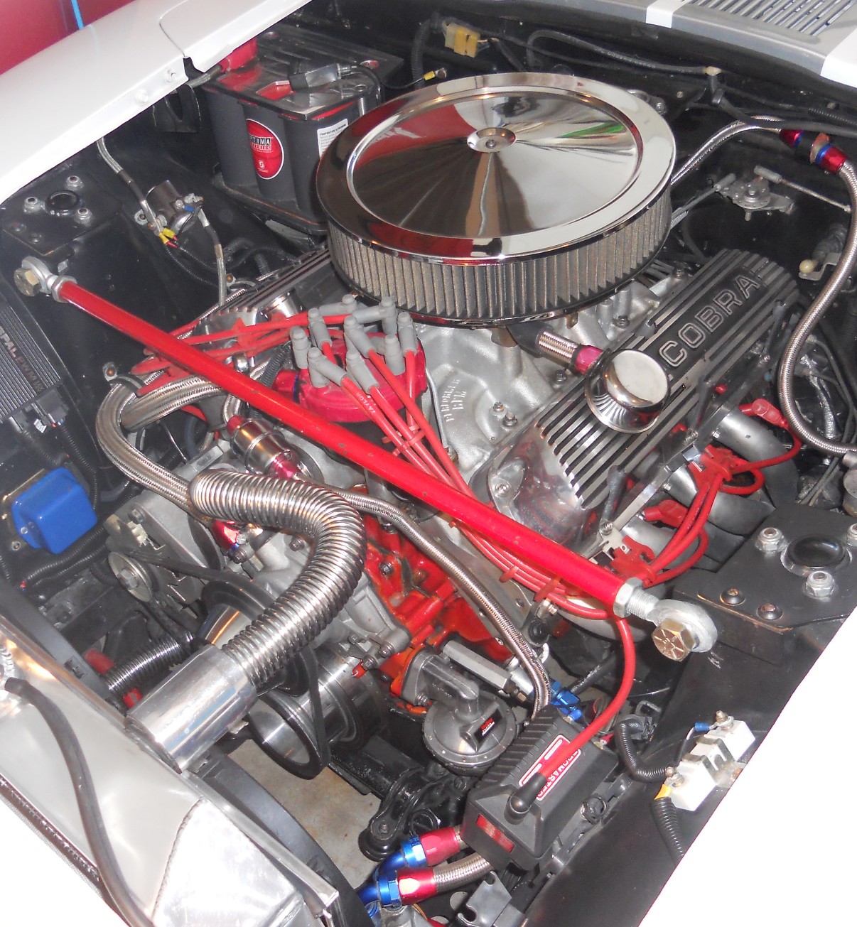
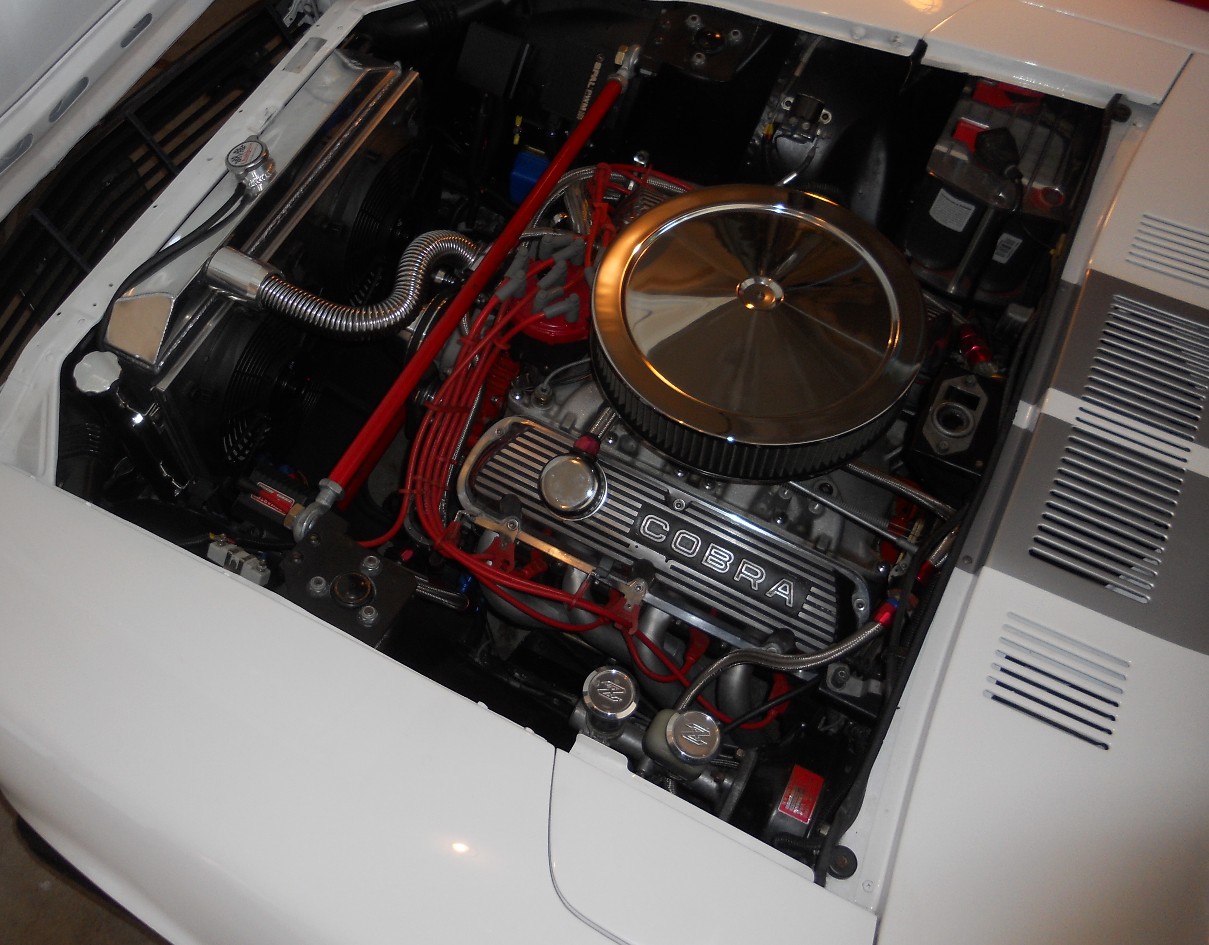
I made my own strut bar and braces. They can be made to fit around single or dual carburetor configurations. I had to also clear the distributor because I have a ford engine. The bars are made removable for access to engine if it ever becomes necessary to remove the engine.
-
I have XXR 521 wheels that are 16 x 8 and have a +20mm offset. I am using 225-50-16 Yokohama tires. I had some billet wheel spacers made that are 19mm thick on the front and 11mm thick on the back. This gives an effective +1 offset on the front and a +9mm offset on the back. I also used longer ARP wheel studs.
I am running stock struts with Eibach progressive springs. Everything just fits and does not rub. I had to take a file and remove about 1/16"-1/8" of the inner rear wheel arch flange (only on top section). It was very easy to do.
-
For those of use with stock struts and insulators on a lowered 240Z, the only practical way to correct and gain more negative camber seems to be lengthening the LCAs. A small gain can be made at the top of the strut, but this is limited to about ¼†or about ½ degree. More gain can be obtained with adjustable LCAs, but the limitation here is the amount of adjustment on the tie rod ends of the steering rack.
Now to the point, I have read that 280ZX tie rod ends, which are ¾†longer, can be used on the 240Z steering rack. The 280ZX rod ends are both right hand thread. The 240Z uses right hand and left hand threads. So to use the 280ZX rod ends, the left hand threaded rod on the rack could be replaced with a right hand threaded rod so that both sides have right hand threads and can now fit the 280ZX rod ends.
Has anyone done this swap? Is it possible?
-
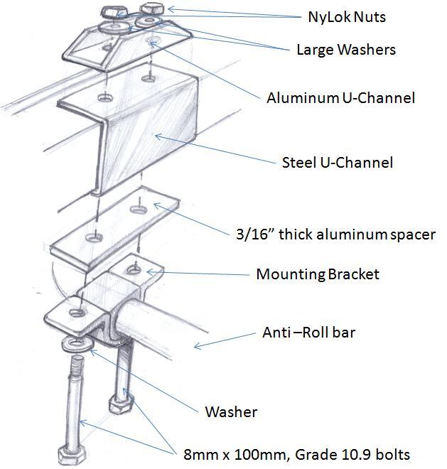
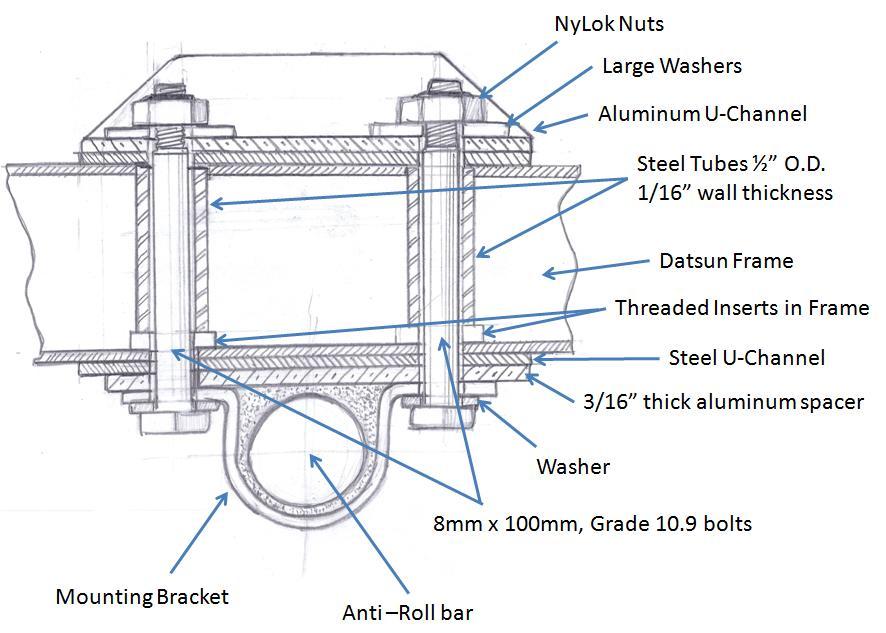
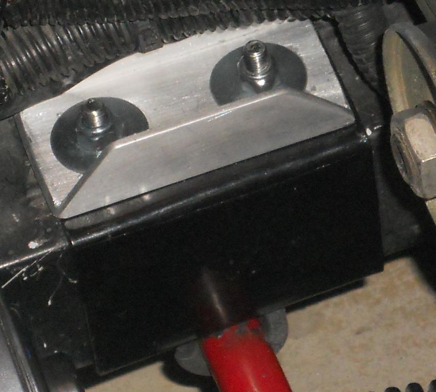
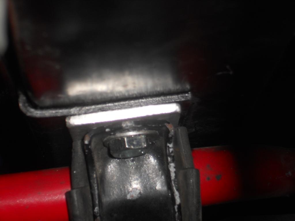
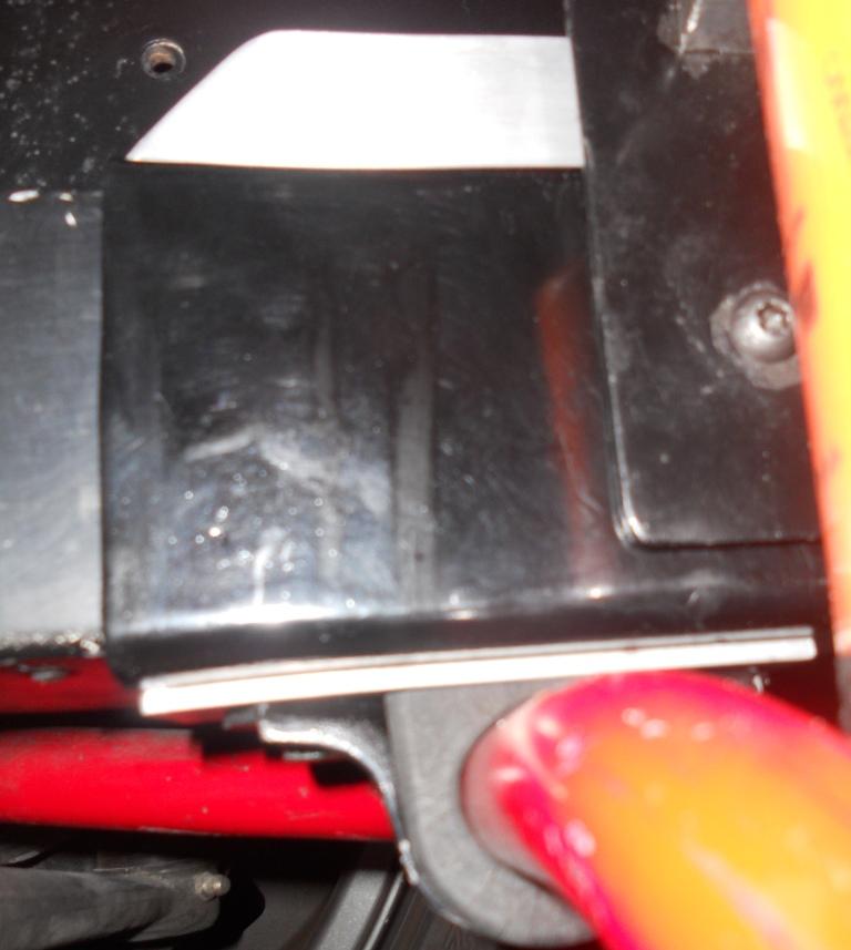
I fabricated some parts that enabled me to bolt on frame and mount reinforcement for a larger front anti-roll bar on my 240Z. I used some 1/8" steel plate that I bent into a U-Channel to fit around the frame rails, 8mm x 100mm Grade 10.9 bolts and lock nuts and some 1/16" wall steel tubing to fit into frame and prevent frame from crushing when torquing down on bolts. While I was installing this, I added some aluminum spacers between the anti-roll bar mount bracket and the bottom of the U-Channel to space the bar down slightly and give me more clearance to my lower radiator hose. Below are some sketches and pictures of the parts and installation.
-
If you want to keep the differential at the stock angle, you should reduce the height of the polyurethane mount. One way to reduce the height is to grind down center part of the mount (a kind of half round notch) so that the mount fits down over the rounded portion of the differential nose. Check the angle of the differential after installing it with the mount and RT bracket and compare to angle of transmission tail shaft. They should be within about 1 degree of each other.
You can get a simple angle measuring tool that has a magnet built into it so it can easily attach it to the drive shaft flange on differential and on tailshaft of transmission to measure angles.
If the drive shaft u-joints are not at the same angle, you can have a vibration, usually more noticeable at higher speed. I have had this happen. No noise, but the vibration shakes car at speed and it is annoying. It's eventually hard on the u-joints and can be hard on transmission tailshaft seal because it causes the drive shaft to wobble.
It's not too hard to grind down the polyurethane mount. I was able to do it with some simple hand tools (hacksaw, files, rasps). Once I got the angles matched, the vibration went away.
-
I was lucky and did not have to hammer my RT mount into place. It lined up with the differential strap mount holes and I was able to install the bolts. Watch out for your fuel lines and any other wiring or lines that run through the tunnel to make sure they are up and out of the way.
If you use the polyurethane transmission mount recommended for mounting the front of the differential, the nose of the differential will be lower than the stock position. This works well for most V8 engine swaps like mine which position the transmission output shaft lower. The lower differential pinion angle aligns the drive shaft u-joint angles and also reduces the overall drive shaft angle. This takes out the vibration caused by out of phase drive shaft u-joints.
If you are installing the stock front differential cross-member (which I did), you will need to make a few notches where the heads of the differential mounting bolts interfere with the crossmember
If you have a motor and transmission located in the stock position and need the differential front located in same position, then you will need to cut/grind down the polyurethane mount to allow nose of differential to align with stock position (I've tried this on an earlier install and it works to get differential aligned to stock position).
With the differential mounted with nose the stock up position, it is possible to install front crossmember without notching it.
-
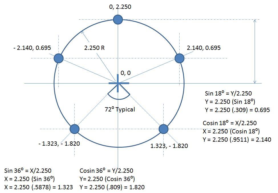
you can calculate the X,Y coordinates of the holes in a 5 lug x 4.5" bolt circle by using the following: holes separated by 72 degrees, radius of bolt circle is 2.250". Use Trigonometry to calculate the X,Y coordinates, See attached file.
Check by laying wheel bolt circle over X,Y layout
-
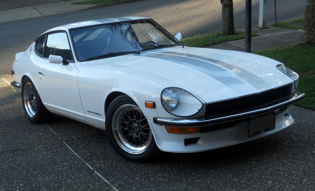
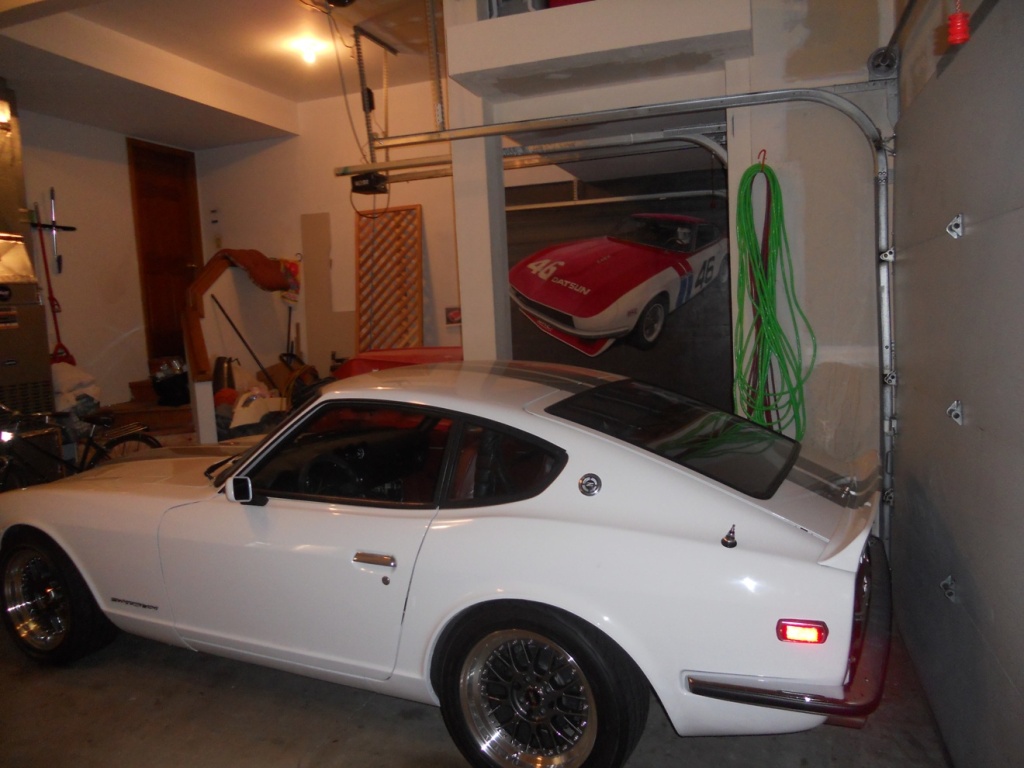
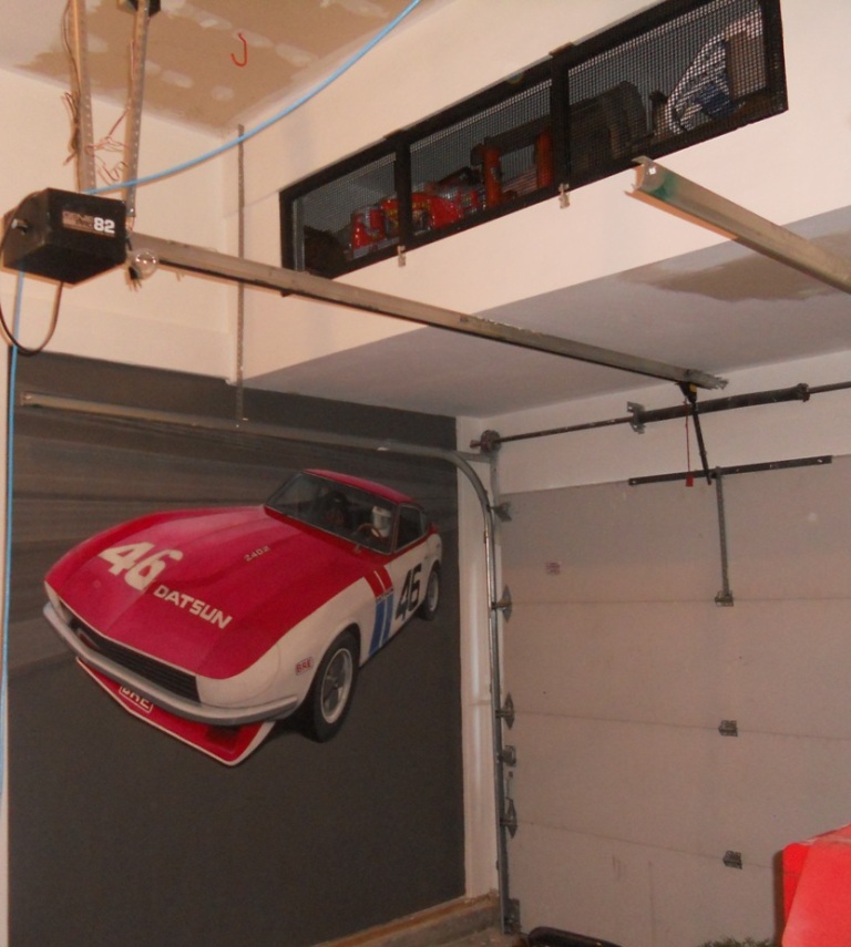
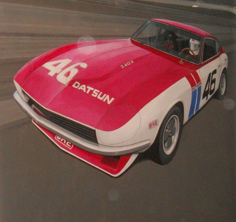
Here are pictures of my 240Z and a mural I painted for my garage. I am in the process of upgrading my garage (built a loft for storage and finished and painted walls), so while I decided that a mural would be nice on one wall.
-
I am running 16"x8" wheels with 225 50 16 Yokohama tires on my 240Z. The car is lowered and has stock struts (no coilovers) and tires fit within the stock fenders. I had to precisely fit the wheels and tires for clearance. In the front, I needed to have +1mm offset on the 8" wheel. For your 8.25" wheel with 0 offset, you will need to put in a 2mm spacer to get enough clearance for the tire to spring perch on the strut. In the rear there is more inboard space. For the rear wheels I used +9mm offset on an 8" wheel. For your 8.25" wheels with 0 offset, you will be hitting the fender if the car is lowered. You will have to roll the inside fender lip flat so that it does not rub. If your car is not lowered, you may be ok with 225 50 15 and bumpy roads (I have 1" taller tires and the car is lowered). Note that the tire section width extends slightly beyond the outside edge of the rim.
-
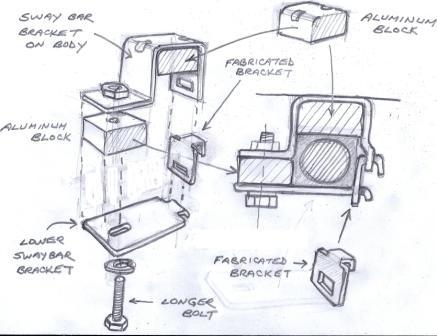
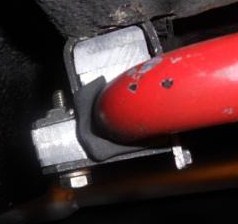
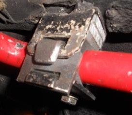
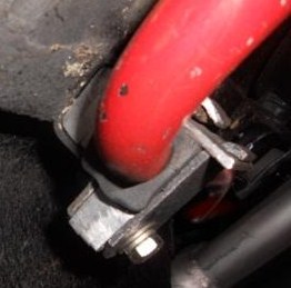
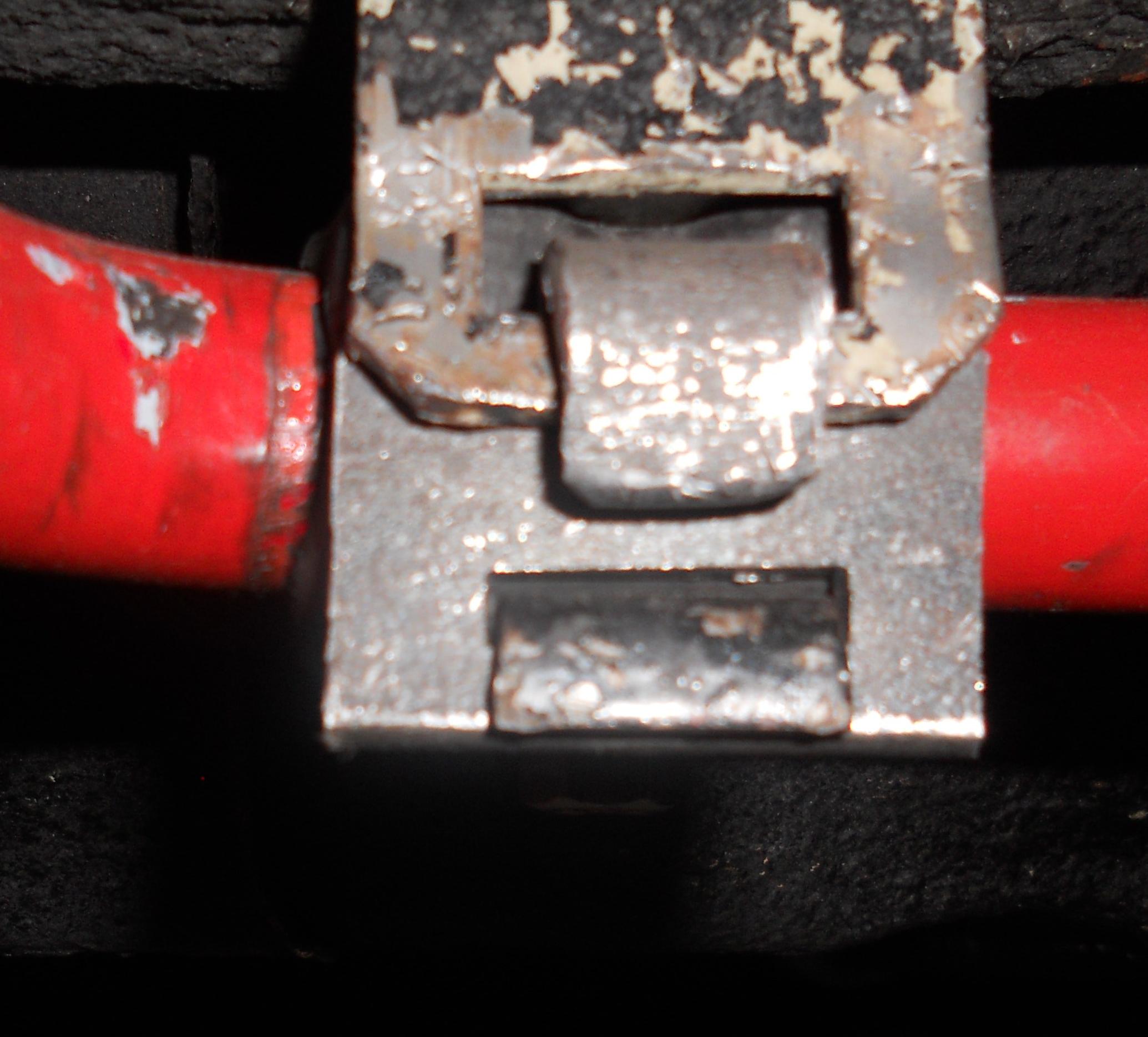
My 1973 240Z has the same kind of rear sway bar mount as your car. When I installed a V8, I had to change the pinion angle of the differential and when I changed it, it hit the sway bar. I fabricated some aluminum spacers and a small extension bracket so that I could lower the sway bar and still use the existing bracket mounted on the body and the clamping bracket. The sketch below describes the fix and also included are some pictures.
-
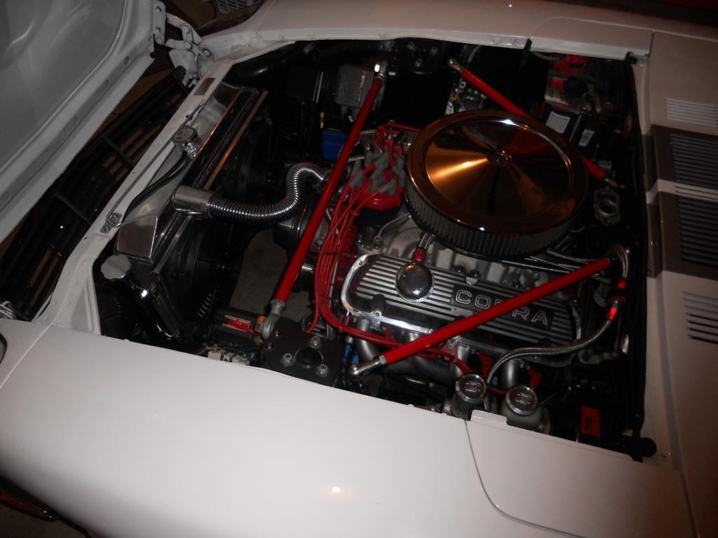
I used a 1968 302 block, bored .030" and fitted with TRW forged pistons. I used the Eldelbrock Performer RPM kit with aluminum cylinder heads (2.02 intake, 1.60 exhaust), hydraulic cam, high rise manifold. I used roller rocker arms and a holley street avenger 670 cfm carburetor. For ignition I use an MSD distributor and Crane Hi6 multispark box. I am running long tube headers. This combination dynos at 360hp and 340 ft-lb of torque. It has a nice lopey idle, but is very streetable.
-
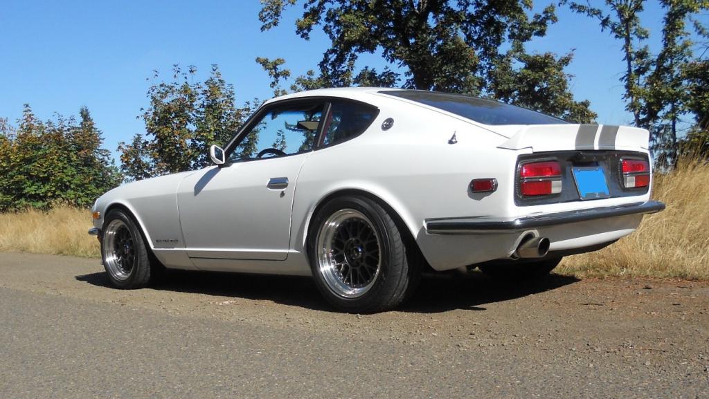
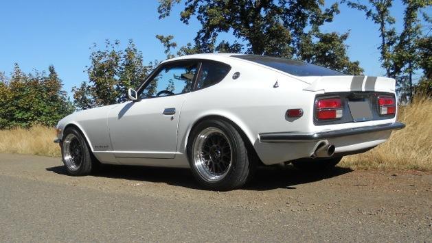
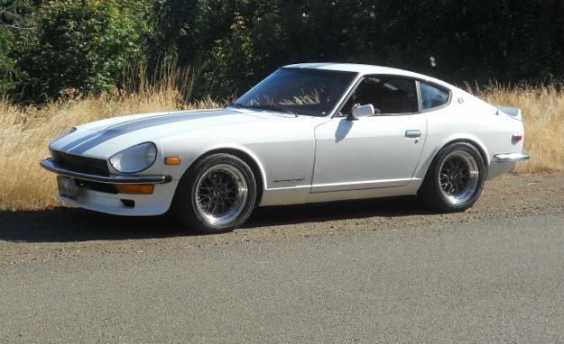
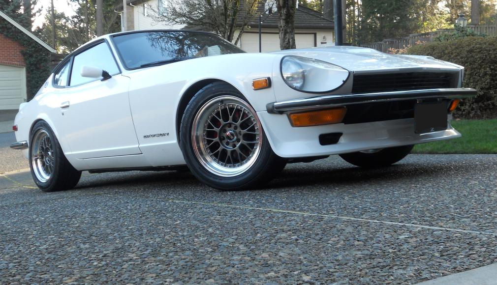
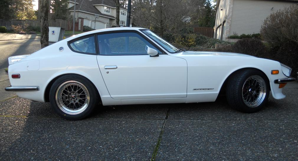
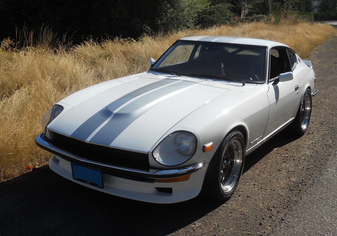
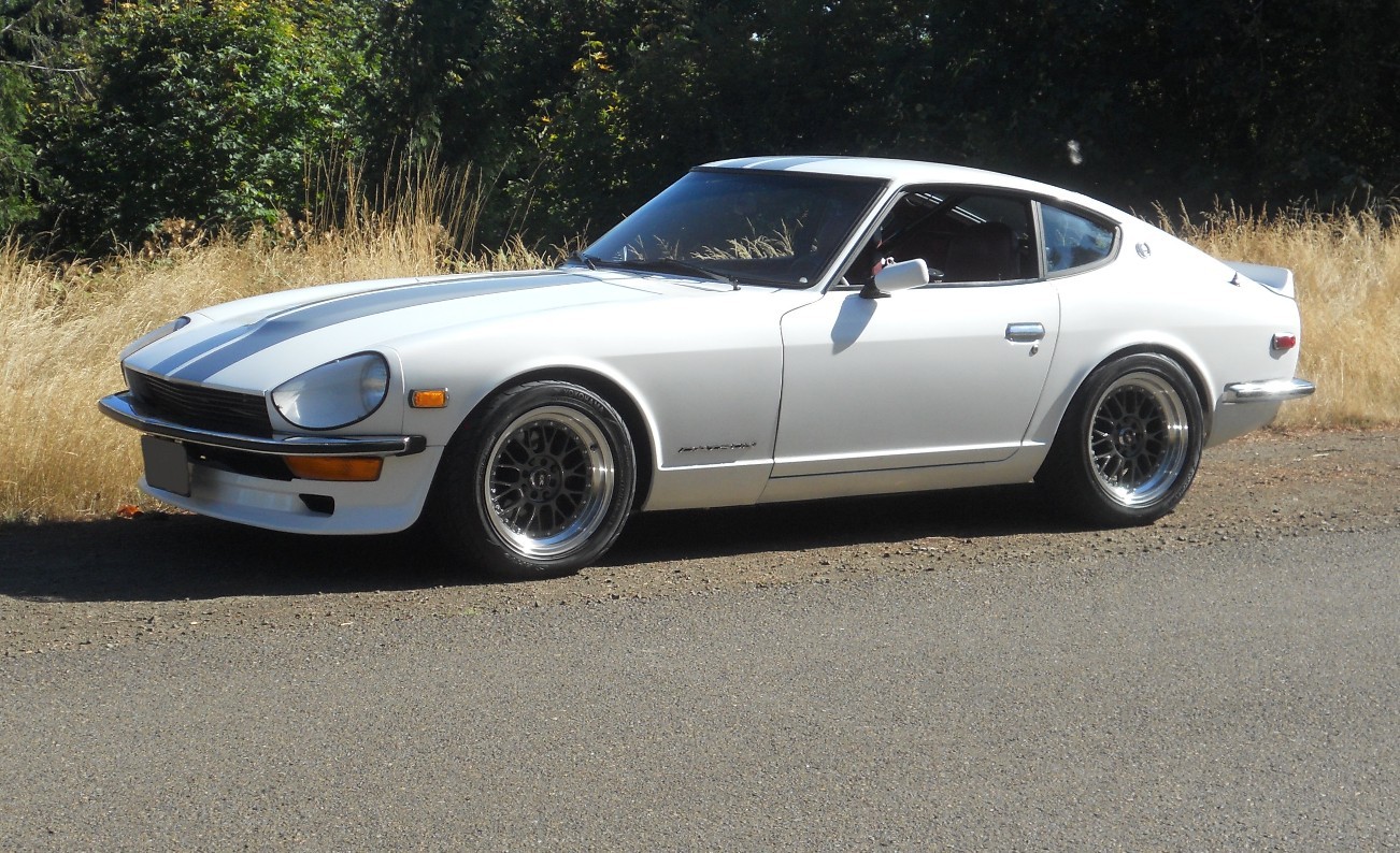
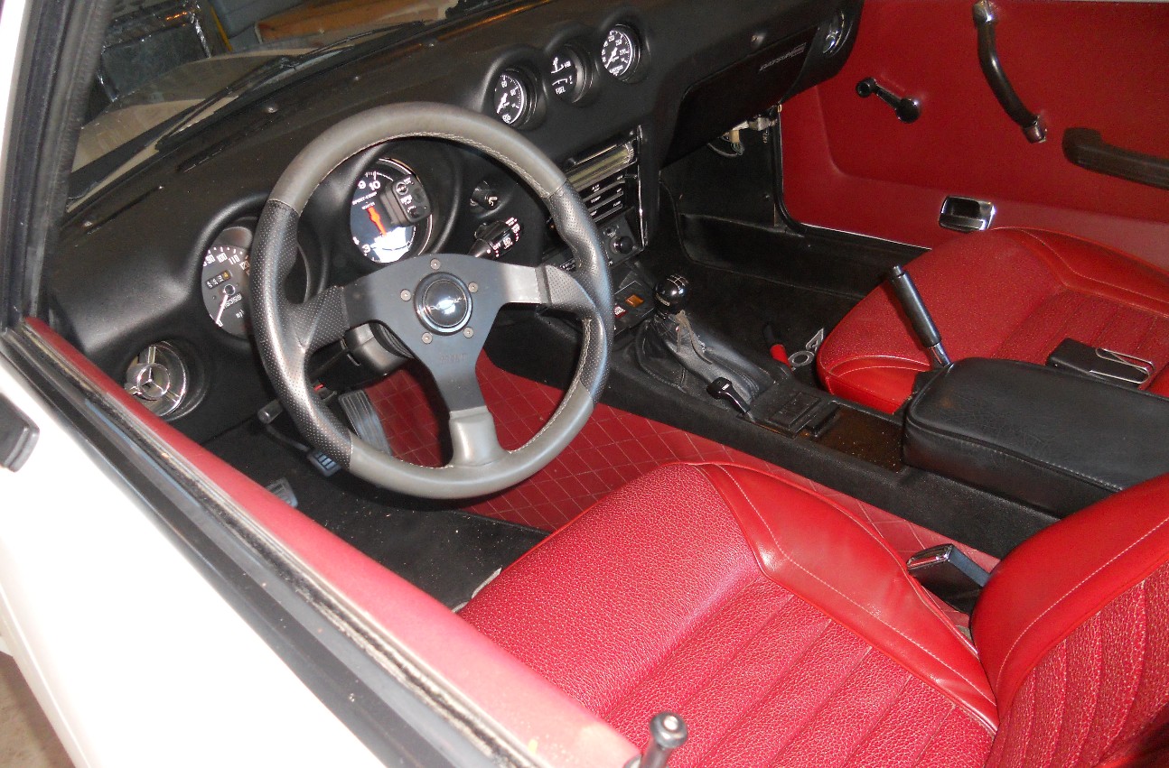
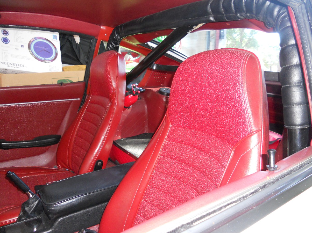
Here is my white 1973 240Z with red interior. It has a 360hp ford 302 with alum. flywheel, Z code T-5 five speed and 300ZX CLSD with 3.70 gears. The suspension has Eibach progressive springs, Tokico 5 way shocks, urethane bushings and front and rear sway bars. Brakes are 300ZX vented rotors with Toyota 4 piston calipers. Wheels are XXR521, 16x8 with Yokohama 225 50 16 tires.


Where to buy 280zxt CV axles or get them rebuilt?
in Drivetrain
Posted
TimZ, thanks for the link to axles unlimited. I'll check them out.
LLave, l saw the ads on eBay. They looked like they were original 280zxt axles and might need rebuilding ( this may be the better option). I saw a lot of " new or remanufactured" axles for less $$. But I've heard that these cheaper axles may not fit 280zxt (may be too long). Also I wonder about the quality and durability of these axles.