
geezer
-
Posts
37 -
Joined
-
Last visited
Content Type
Profiles
Forums
Blogs
Events
Gallery
Downloads
Store
Posts posted by geezer
-
-
Okay geezer, if you don't mind I would really appreciate the measurements of the scoop...
I just noticed your post. Sorry, bad timing, I sold the hood 4 weeks ago.
-
Pull a spark plug, feed in a length of 3/8" cotton rope leaving enough rope to remove it later. This will prevent the piston from reaching TDC and lock the rotating assembly allowing you to apply enough torque with your breaker bar to remove the crank bolt. Good luck!
-
This is not a good picture of the hood but I think it is the same. This was from this recent Ebay auction.
http://cgi.ebay.com/ebaymotors/Datsun-240z-260z-280Z-Jim-Cook-Wide-Body-centerline-/320622674635

-
I have the same exact hood that is pictured on Eric Bernstein's IMSA 240Z. I got it as a package deal, with my car about 5 years ago and didn't know the origin of it, but suspected it is a Jim Cook hood. I've had it stored away ever since I got it. I don't know the composition of materials, but it is very rigid and easily lifted with only one finger. It is in primer and has never been painted. If you want pics and dimensions, I can make the short trip to do so.
-
I dug up an illustration. Just as jasper pointed out, you have it backwards. It's kind of a generic drawing and doesn't show it but from looking at your pics, I'd say you have it upside down also.
-
Upside down?
-
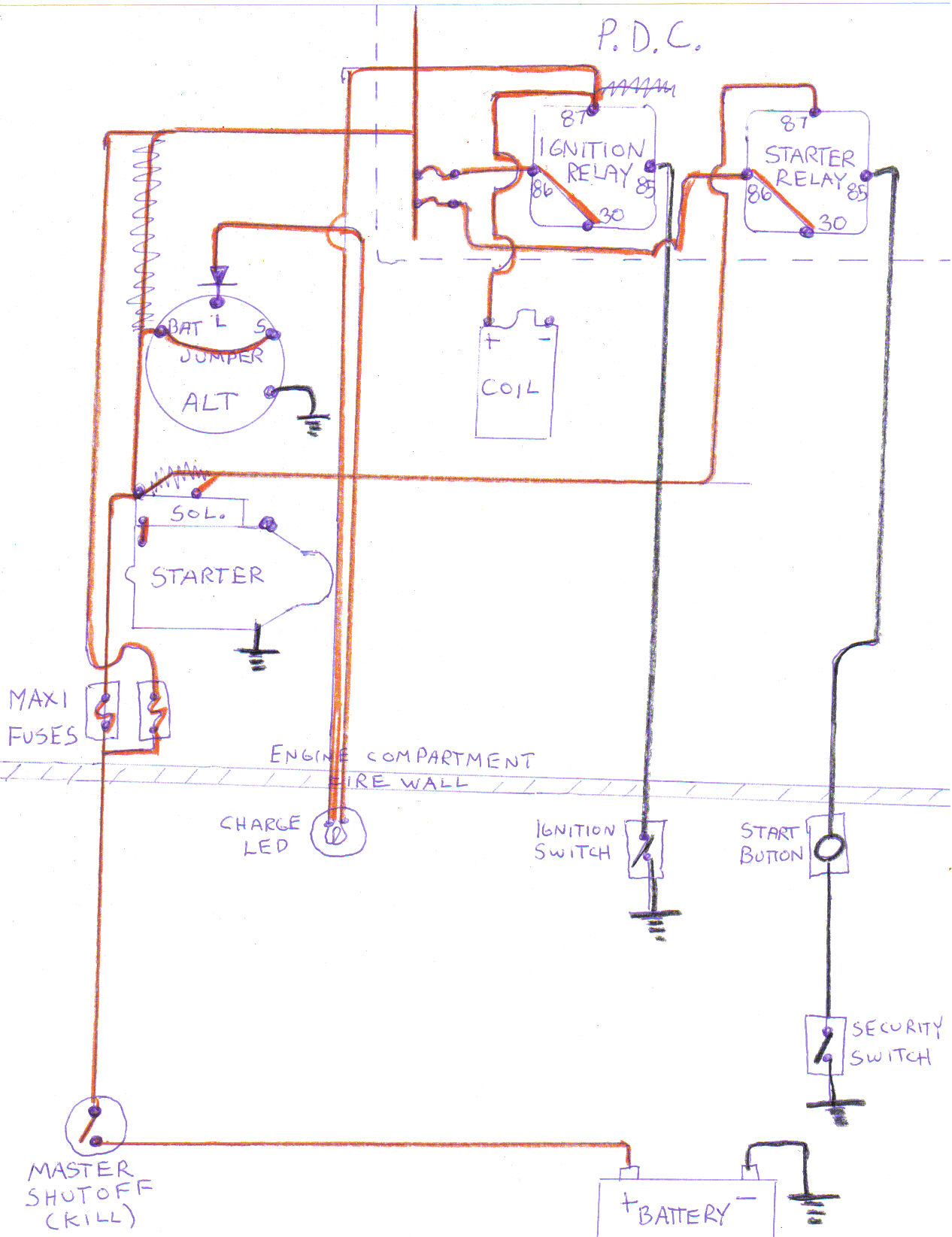
It is good to go, as far as keeping with your minimalist theme. If it was my car, I would use whatever extra wire was needed in order to separate the control side of the relay (pin 86) from the battery power (pin 30), using seperate fuses to protect, but it will work as is. A few more details will have to be kept in mind when you actually implement the plan. It would be a good idea to separate the bus bar (fuse feed), so the headlights high beams and low beams and perhaps the fog lights are derived/grouped from a dedicated Maxi Fuse. Look at any fuse box and you will see that the high amperage draw items have a dedicated wire and fusable link/maxi fuse connecting to the bus bar. Just something to keep in mind, instead of having 1-150 amp Maxi Fuse covering everything on 1 bus bar. That is something you can decide on when the components come together in the car. Each end device/accessory and length/gauge of wire used will have to be evaluated in order to assign the proper sized fuse for each. You can never go wrong by using too small of a fuse to start with. Good luck and I hope I was helpful.
-
gotcha. tomorrow i will be pretty much free and clear; as most of it will be running around getting the brake lines that i need and researching on the proper initial tuning of the carbs, so i'll be able to make the changes that you mentioned.
for the 30 to 87 swap all i would have to do is swap the numbers correct? So it would be 85 ground switch, 86 feed form mini fuse, 30 jumpered to 86, and 87 gives power to object?
Yes, just change the numbers. The reasoning is, Pin 87A can be utilized if you abide by the "in 30 out 87" rule. If you wished to incorporate the Fuel Pump Shutdown Relay I showed you, this comes in handy, as well as in many other circumstances.
-
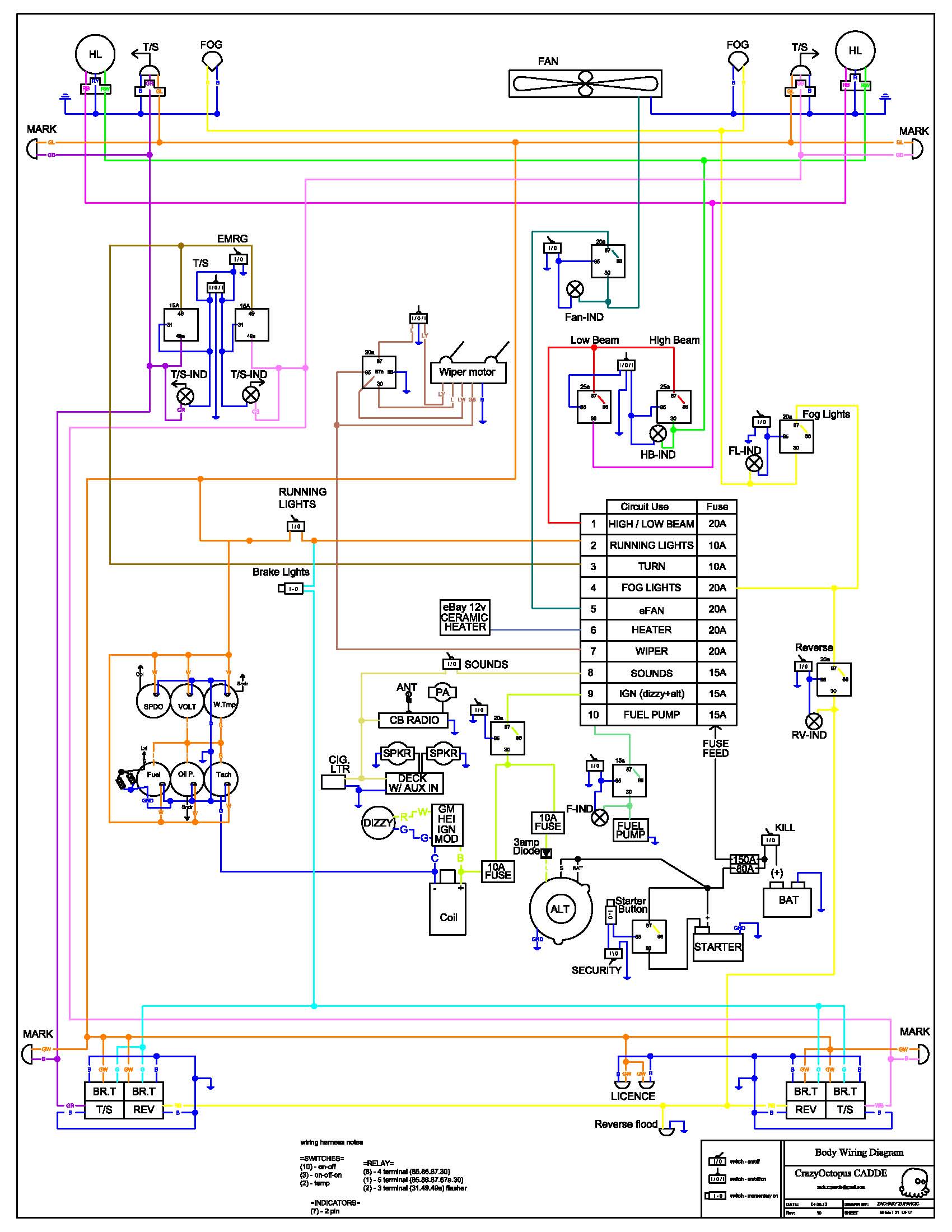
here is the updated with geezer's relays taken into place; didn't add the charge led though. When I showed this to the co-creator he was told me to "stop changing the layout!" but I think that having the starter on a ground switch is awesome.
larger http://farm5.static....dfa414f76_o.jpg
once i get the car started up and running well, I will be attacking this on some plywood and getting the drawings laid out exactly like it would be on the car.
I did not look at this latest diagram close enough before saying it was a good plan. I was pressed for time and just assumed that you followed the example in my diagram. You changed it up and compromised the Starter Relay circuit's protection. You have not made the distinction between Maxi fuses and Mini fuses. Take another look at the way I have Pin 86 and also because it is jumped, Pin 30 protected by a Mini Fuse in the PDC. Same as the Ignition Relay. The Starter Relay is only being used as a means to control the Starter Solenoid with a Ground. The Maxi fuse is intended to protect the downstream cable coming from the Battery and the Starter Motor only. The way you have it configured the Starter Relay and associated wire can go up in flames before the Maxi Fuse blows.
Take another look at my example diagram. Its a crude drawing, the Mini Fuses aren't labeled, but everythings shown to make the Starter circuit safe and reliable.
-
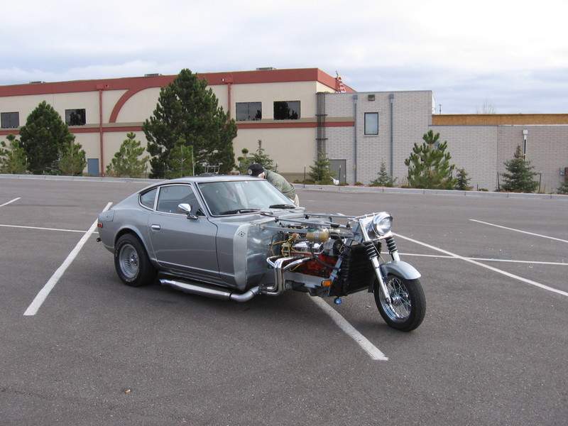
Bleh I don't like it, its like grafting a banana onto an Orange. Two different body types of two different cars smashed together to make something different. Sort of like a bolt on spoiler "it must make it faster lololol", except if you put on a S30 front end you make it retro. Just my opinion though.
Probably won't care for this either.
-
I didn't have to replace my front frame rails because they were done by the PO, but I did replace the floors, supports. outer rockers, quarters, etc. I think it would be easy enough to replace the front frame rails and position them correctly also. The dimensional body schematic in the FSM is good to have. Maybe I'm not the right guy to answer your question. I didn't use a frame rack or any type of jig but I did have the car mounted on a rotisserie, that made it extremely easy to level the car perfectly while upside down. When these cars were built, platform jigs were used to position & clamp the frame and floor components correctly prior to being welded together. Knowing this and since the rear frame & floor section were still in great condition, I used a lazer level mounted across the rear frame section to project a consistant reference point along the horizontal plane of the car. I also had taken and recorded several measurements before cutting out the rusted sections. It made it easier to position the new floors and supports. A homemade rottiserie along with a dimensional schematic and a lazer level worked great and with a little ingenuity you could do the same without the rottiserie and the car leveled right side up. I didn't take pics of the lazer level use but I think you can visualize how easy that is to do.
After I had the laser level mounted square with the rear frame section, the line projected stayed consistant no matter what position the rottiserie was in.
-
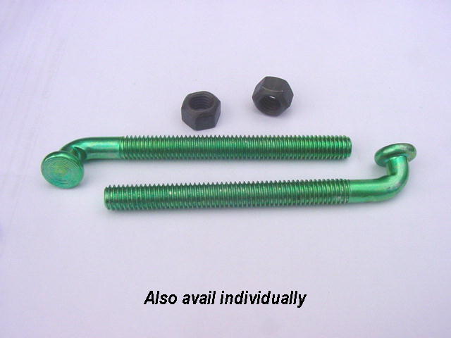
These J-bolts are available for $14.00 a set at amhightechauto.com. if the Nissan ones aren't available or too expensive. The Mopar ones I have do not have the proper bend and they have a stove bolt square shoulder also.
-
More info...The fuel tank and strap changed with the introduction of the '74 1/2 model. This is when the fuel tank capacity increased to 17.2 US gals from 15.8 US gals. So with what Nigel has said, that makes 3 different sets of straps for the S30. Just trying to help you draw a line for the different usage. I can look it up in the microfiche for you if it will help others when ordering.
Edit: The Gas Tank Strap part numbers 17410-N4500 (RS) & 17405-N3400 (LS) are shown as being used from 09/74 - 07/76. That pinpoints the use of all 3 different sets. Hope that helps.
-
It appears to be the same kit as the one on this car in the link, although not executed quite as well. I recognized it and saved the link because I have what I think could be a Jim Cook hood. It looks identical to the one shown in this link. I haven't checked out the composition of the hood yet or weighed it. It is in primer and so lightweight, I can lift it easily with 1 finger, yet it is very rigid & strong.
-
its a fairlady z but i dont think it should make a difference)
There is one difference in the headlight circuit for your FairladyZ. You have what Nissan called a "passing switch" on the end of the turn signal stalk, used to momentarily flash your lights to signal other drivers. Better known as an "optical horn" here today.
Here is a drawing of the headlight circuit that does not include the "passing switch" or associated relay. Everything else is the same. We draw the individual circuits like this to make them easier to follow when trying to explain to someone how to troubleshoot a wiring problem.
A brief explanation: Turning the Headlight Switch to the on position provides a ground path to the Dimmer Switch. Both, the red with black stripe & red with white stripe wire become a ground path when that position is selected but only when the headlight switch is turned on. The left side & right side headlights get their 12V feed from seperate fuses in the fuse box. Excuse the drawing, it was a rough draft and doesn't show the connectors, pin outs or other details.
First question I have is..Did the high beams also go out?
-
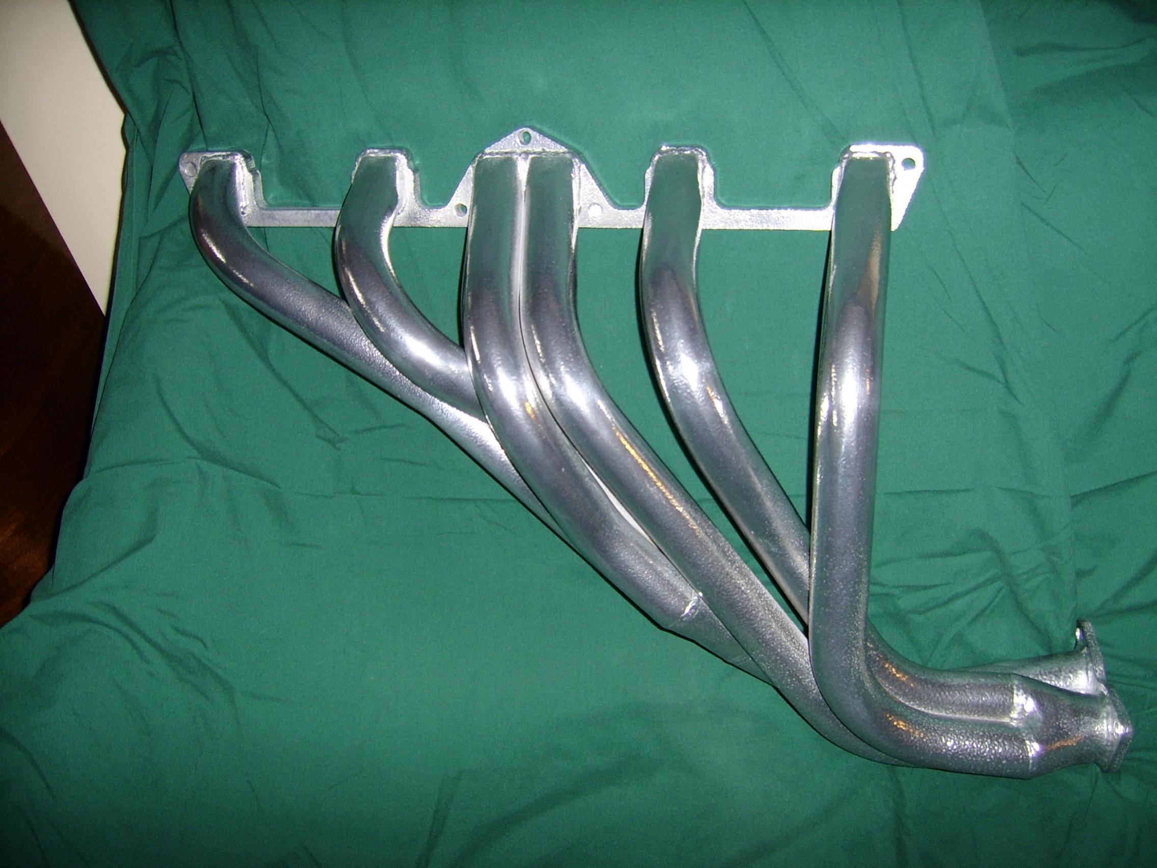
Jay, until you get an answer from Sylv1 on the intake fitment, I can tell you I had absolutely no problems mounting 4 screw SUs or triple Weber DCOE 45s with a Cannon intake, with the Trust header I pictured.
By the way, you have done an outstanding job building your header especially having only a picture for reference. Very nice indeed!
-
Or completing a beautiful tight bend while forming your stainless brakelines...then realize you have left the fitting on the wrong side of the bend, with no easy way to fix. Yep, hate it!
-
It sure looked like it would fit, but it is hard to tell from a picture. As far as performance gains of one style over another, I think the difference would prove to be minimal, but from a marketing viewpoint it is a huge advantage to tap both RHD & LHD markets with a single design. Good luck with your venture!
-
JDM RHD :
What exactly is this one in your pic? It looks like the primaries could be equal length but other than that, it is similar to a Trust header I have that does fit on a LHD without steering shaft interference. I wonder if you would get a little more interest if the design could be tweeked so this header could fit both RHD & LHD. I have had the one in my pic on a LHD.
-
if you're only going for a year, why not get the beast tuned for canadian gas, and ship it over under a carnet du passage. Sort of a passport for cars. Theres a time limit (12 months IIRC), and the car MUST leave after the time limit, so no selling it to a canuck, but it would let you take your own car.
That would be a pricey venture for the amount of actual use of the car in our Canadian climate.
-
ok, how do i paint hte back slotted sections where I just stuck the sandpaper on a stick?
rag dipped in paint? hehe
Get yourself a shutz gun or a cheap equivelent. Most of them are easy to adapt a length of tubing/hose onto the nozzle for reaching into hard to access areas. I had (key word "had" as in can't find it) an old brass lawn sprinkler tip fitted to a tube and shutz gun that I would crank the pressure up to about 60 psi. It works well, with whatever you choose to put in the gun. Just find a good place to keep it, for the next time you need it.
-
Every different brand name or product from within a particular company will have different formulations, based on intended use, price range, etc. Therefore the answers to your questions can best be addressed by the company who developed the product. Other than that, I can only echo what ZR8ED has told you, it is best to use a "total paint system" to ensure compatibility and adhesion between the components. If for some reason you cannot get this information from your paint supplier, your best bet is experimentation on a few test panels. If you are forced to thin the product for spraying, only thin the amount you will be immediately using. If the test panels don't work out well, you will have to go beyond the salesman you have been talking to, in order to get the relevent information on the products you are using. Good luck!
PS - I have successfully experimented using different brands and I also have had catastrophic failures.
-
A search should have turned up this source. Highly recommended!
-
This is the business end of a crimper made by Essex terminal that I have used for over 40 years. They turn up on Ebay for cheap quite often and will do the job.


Steel Brace for R200 CLSD Finned Cover in S30; New List and design...
in Vendor's Forum
Posted
Payment sent. Thanks for all your help Richard! I really appreciate the effort you have put into these.