

hoohaa
-
Posts
96 -
Joined
-
Last visited
Content Type
Profiles
Forums
Blogs
Events
Gallery
Downloads
Store
Posts posted by hoohaa
-
-
I've got a normal length run from the glove box to the motor. I bought some 25 conductor cable with 24 AWG color coded stranded wires. I have read different suggestions from different places about wire size, some saying 18 AWG for everything and some saying 14-22 AWG.
Would 24 gauge wire cut it for some of the sensor circuits? I won't be using anything smaller than 14 AWG for the injector circuits, grounds, fan, and stepper IAC circuit.
I will have the harness very well protected throughout the run.
-
Yeah I was referring to what you would do differently if you were to go back to the dyno.
-
Is there anything you would do differently?
-
I've wanted to hear from someone who has built one themselves from the circuit on msextra.com but I will probably end up buying the viatrack sensor as well. It's already built and proven to work and pretty cheap.
-
lol by the weight of your foot? lol

That's what I thought. Haha something tells me any savings on a lean cruising tune will be canceled out by the heavy foot people always seem to get when driving a car with the kinds of goodies that normally go with MegaSquirt.
Still, a lean cruising tune sounds like music to my ears, and like... I dunno, leather conditioner.... to my wallet.
I've always assumed you could match or beat most stock EFI cruising tunes for fuel mileage. Lean it out as far as you think you can under low load, then dump in the fuel under highest loads, with programmable maps and target AFRs in MS the only limit is the amount of time you want to spend getting everything perfect.
-
This is exactly what I'm planning to do when the time comes to wire up the motor and MS. I want to use a single heavier gauge ground wire (probably like 10 or 12 awg) and remove patches of insulation, solder in jumpers to all the grounds on the motor, then seal the connections up with good heat shrink.
The 12 gauge wire is more for mechanical strength than for conductance, I figure that it will take a beating if I'm constantly stripping and soldering to it, and it needs to be fairly tough.
The DB37 side connection can be done simply by stripping off enough of the ground wire insulation, laying it over or wrapping it around each MS grounded DB37 pin, then soldering it.
I would also like to see pictures of people's wiring harnesses. Especially if they took lots of time to do a nice clean job. There are not a lot of MS wiring harness pictures that I have seen on the various forums in which I lurk.
I don't know where it is, but there is a picture of an L28 Z car (perhaps BRAAP's?) that has a pretty clean looking wiring harness. What I like specifically about this car is that the injectors were wired in such a way that the wire fit inside a very small split loom and stretched in a very straight line across the tops of the injectors. It came out looking very clean.
-
Have you read through the MS faq and links at the top of this forum? That's where I started after I had read completely through the megamanual. There is a ton of information in this forum answering all your questions in detail. The FAQ and links threads are the best place to start.
I went with MSII, because it's not that much more expensive and it is the platform that is being developed now. The MSI code has reached its zenith and will not be developed further. With MSI you can really do everything you probably ever want to, but I have a hard time saying "no" to more toys, such as I get by running MS2Extra code.
-
Ken (muythaibxr) gave me this response on the MS2Extra forums:
It (%age) depends on what you set for "load"If you select alpha-n, it's % throttle, if you select Speed density, it's kPa, if you select % baro, then it's a percentage of the barometric pressure.
I am not sure how I missed that little tidbit in my reading of the manuals and the MSExtra forums, but I did. Hopefully this thread will help someone down the road.
Thanks Matt!
-
That would explain why I cannot find a way to change it. Am I correct in understanding that the percentage is actually based upon the range of the map sensor rather than the actual boost measurement, i.e. "100%" could be 250 kpa for the standard MS map sensor or 300 kpa for an upgraded sensor?
This is not a problem for me unless I decide to go with a larger sensor, which is unlikely. It is also adds on more step of abstraction since I will be converting percentage to kpa and then to pounds of boost, until I can start thinking in kpa rather than pounds boost.
-
I'm a little embarrassed to ask this. I had a MSII B&G msq set up, but then I converted the MSII to run MS2Extra code. After I made the conversion my MSII had the kpa axis of the VE tables listed in percentages rather than a direct kpa value as it did in MSII. I want the VE table to be based on actual kpa values rather than percentages.
I know there is some way to change this, but for the life of me I cannot find it. I've looked all through MT and the MT configurator, but I have not found a setting page where I can change this. If someone could help me out I would really appreciate it. I don't think the MegaManual mentions this since it's a MS2Extra issue.
-
I just ran across this thread: http://www.msextra.com/viewtopic.php?t=24702
GREAT info on the Nissan CAS distributor and MegaSquirt settings. You must be a forum member and logged in to view the files. I have them archived if they are ever taken down.
-
I'll check on that. I'm only planning to use PWM, so that's fine.
-
Something in that stepper motor circuit must be shorted and drawing too much. It shouldn't have mattered whether it's drawing from S12C or the banded end of D9 as it's essentially the same location. Check Q4 and Q20 for bridged pins and also check D8, R19 and R39 just in case.
Do you think I still need to check these components even though I'm up and running fine now? Q4 and Q20 have been thorns in my side from the very beginning. If I could have board problems that are just lying dormant for now then I probably need to desolder those and be careful not to use too much solder this time.
-
I'm eyeing this thread with interest to see what's mentioned about o'scopes. I would love to buy one and learn to use it, but if it's going to be too expensive to find one that actually does what we need it to then I'll have to pass.
-
"A bimetal, heater and rotary shutter are built into the IACV-air regulator. When the bimetal temperature is low, the air bypass port opens. As the engine starts and electric current flows through a heater, the bimetal begins to turn the shutter to close the bypass port. The air passage remains closed until the engine stops and the bimetal temperature drops." Located on the passengerside of the intake manifold.
Yes megasquirt can control this unit. It mearly has to give it power. It needs ignition power only. Once a certain amount of time has passed (I don't know how long it takes) The heater inside warms up and closes the air valve. This remains closed until the vehicle is turned off AND cools down. It is simply a valve that allows extra air during cold startup and idle.
The idle valve (located on the drivers side of the intake manifold) is another story. I have always had problems with mine since the install and mods. I have unhooked all the wires to it. I then blocked off 98% of the air flow. (98 is a guess) I had to block off most of the air, because with no power to the unit, it sits wide open letting all kinds of air in. It has a couple of spring loaded actuators that bypass air, and move with the pulses in the intake manifold. Those acuators keep the idle stable.
I don't fully understand that unit. The car will not idle properly without it. The idle will surge without the actuators (I removed them as a test)
I can't really offer much else, other than with my megasquirt, I am going to use it to control my warmup bypass, but i will continue to use my butchered idle control valve.
BTW why are you using a pathfinder FSM? are you using a pathfinder vg30?
Scott.
I'm running a Pathfinder manifold on a Pathfinder VG30E.
I bumped into some good info on the PWM valve on some Maxima sites. I will update this thread when I determine which sites are most salient.
-
Good to know. Any thoughts on why I had this problem? Do you think it would not have been an issue had I used S12?
The MS2Extra manual needs to be updated if this is true. It clearly states that the 12v lead should be taken from D9.
-
gWell I went through the troubleshooting guide and still had the problem. Then it occurred to me to remove the +12v jumper to JS9. The MSII now works flawlessly. I don't understand this, I followed the instructions in the MS2Extra manual:
I have MS2Extra code loaded, so I am not sure what I need to do. The MS seems to be functioning on the stim board without the +12v jumper right now.
What a headache. I checked a lot of connections today.
-
Reflashed to MS2Extra, still no go. Reflashed to MSII code, no go. Reflashed back to MS2Extra again, the same problems. It's still not behaving normally, so I disconnected power and checked the resistors and diodes with my multimeter's ohmmeter.
I get .938 ohms flowing from the banded end of D24 to the non-banded end. I get .582 ohms flowing in the normal direction.
D19: .448 ohms normal direction, .496 reverse
All other diodes behaved as I thought they should (what I just reported may be normal for these diodes, I had no other diodes like them to compare with).
I redid the voltage check between the grounds and +5v sources on the 6 pins of the DIP40 socket as specified in the assembly guide. All checked out.
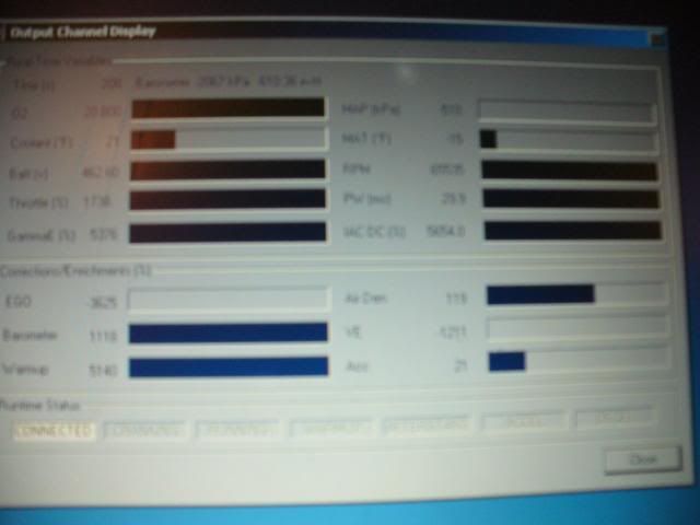
Ok, after I checked all this I plugged the daughterboard back in and fired up megatune. I am now seeing 14.8 volts in the realtime display and I have working TPS, IAT, CLT pots that show expected values in the realtime displat. O2 pot does not change and reads 12.1. RPM does not change and reads "0". "IAC DC (%)" reads 100.
I am thoroughly confused now. What gives?
I decided to play with my 9v batteries.
When I plug in a nearly dead 9v battery (7 volts), I see RPMs and O2 responding to the stim board (which I did not see when plugged into the 12v supply). I plug in a fresh 9v battery with 9.0v charge and I have no rpm nor O2. The realtime display readings seemed "unstable" when plugged into the dead 9v battery.
-
I've got a JAW wideband reader on the way. It's a DIY kit that offers datalogging and programmable outputs. $45 FTW! Total cost comes out to around $110 for me for the reader, a new connector, and the new sensor.
-
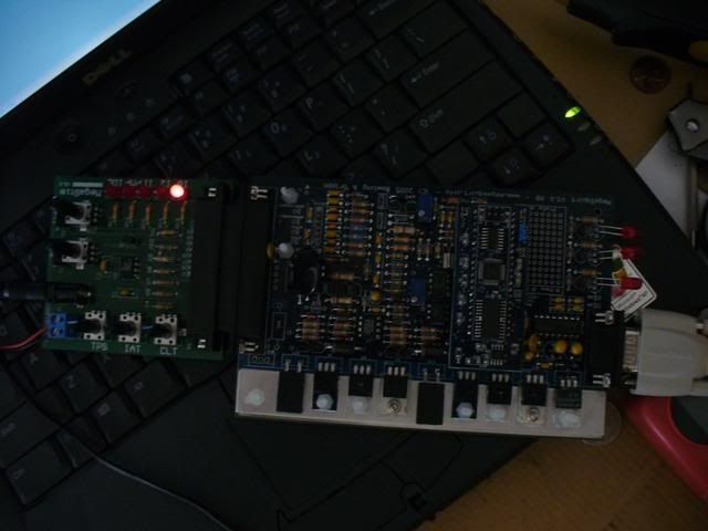
I knew I would get chided for not having the board on a mat. Sorry guys. I will try to do better next time.
I promise that's not normal operating procedure.I'm going to try to reflash the MS2Extra code and see what happens. Wish me luck.
-
Well I have not found much more info on the WD21 IACV-AAC that I've read in the FSM, so I guess when I get to that point in the install I will give it a try. It sounds to me like there are two different systems functioning in the same package. A small heater that runs off of ignition current and functions independently from the engine's idle or temperature, and an actual idle air valve to increase idle under high load, whether from the AC, the power steering, or something else. Of course the heated valve is no problem, that will function on its own. However, this idle valve sounds to me like it's controlled by the ECU with PWM. I am going to try to get it running.
-
I believe the best option will be to use a z31 lower manifold. I just confirmed that this is possible. The pathy manifold FAQ on z31.com was down when I tried to check.
-
Here is a blurry camera screenshot of MegaTune reading 460 volts. The pic of the MSII is showing the single ignition light.
-
this is for a h1e, which is pretty similar. sorry for the quality, i had to take a pic of my comp. screen.
I sent an e-mail to holset a while ago with the tag # on my hx35 and they sent me back a map for a hx30 in pdf form. I can send it to somebody if they want to convert it and upload it.
HX30e or HX30W? From what I've heard they are very different. I've seen an HX30E map, but I don't know where you would buy one of those. Never seen an authentic HX30W map.

24 AWG for some of the harness?
in MegaSquirt
Posted
Thanks for the replies guys. I think I might run the tach input through a shielded twisted pair cable as was recommended by zya and also run separate heavier gauge wire for the grounds rather than using multiple conductors out of that cable. I don't know, we will have to see when we get the motor in there!