

74.5 347Z
-
Posts
71 -
Joined
-
Last visited
Content Type
Profiles
Forums
Blogs
Events
Gallery
Downloads
Store
Posts posted by 74.5 347Z
-
-
Nope, but I did stop by on Sunday and aired up the tires and opened the rear hatch. The rear quarter panels are fiberglass.
-
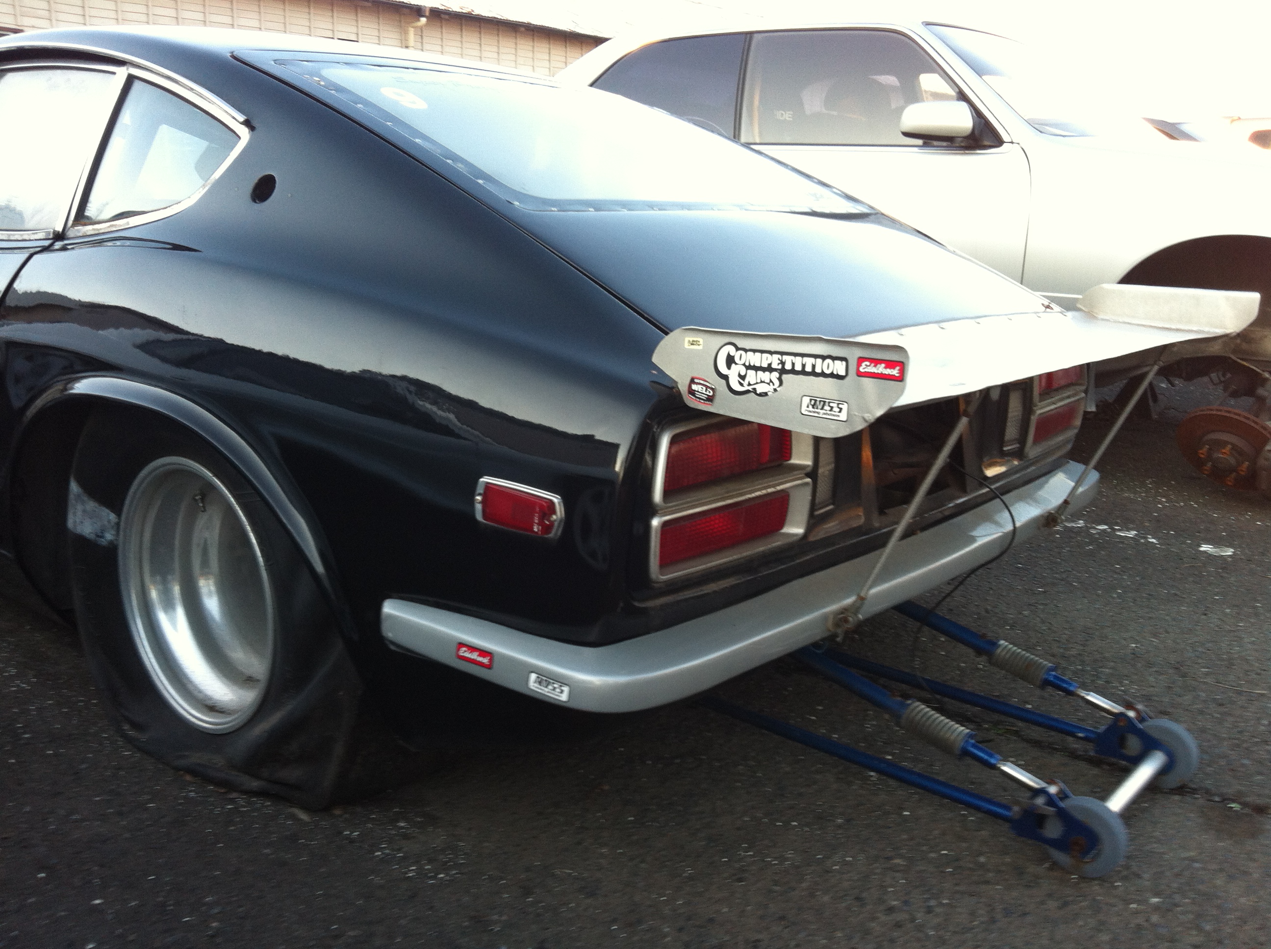
Just wondering if anyone has seen this car and knows a little about it's history. What little I've heard is that it was brought to Japan from Canada. Some guys here had the intentions of putting a RB26/Lenco and racing it over here. But it has just been sitting like this for a few years. It is a full tube chassis, tubbed, 4-link, etc. No engine/trans, just a narrowed 9" and the inside has been torn out.

I'm thinking about building it as a Pro-Street if the price is right. What do you think? Would it be worth it?
-
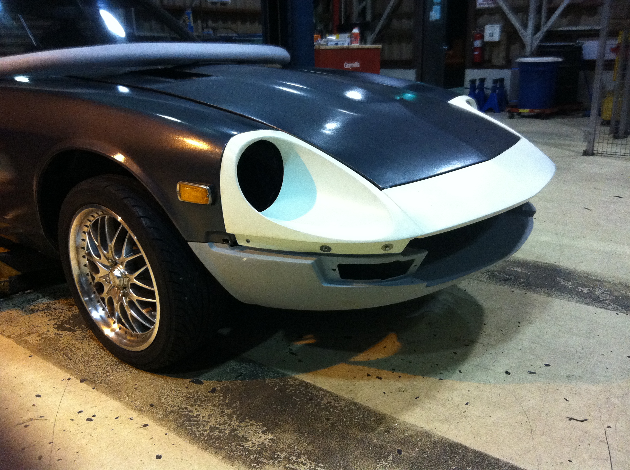
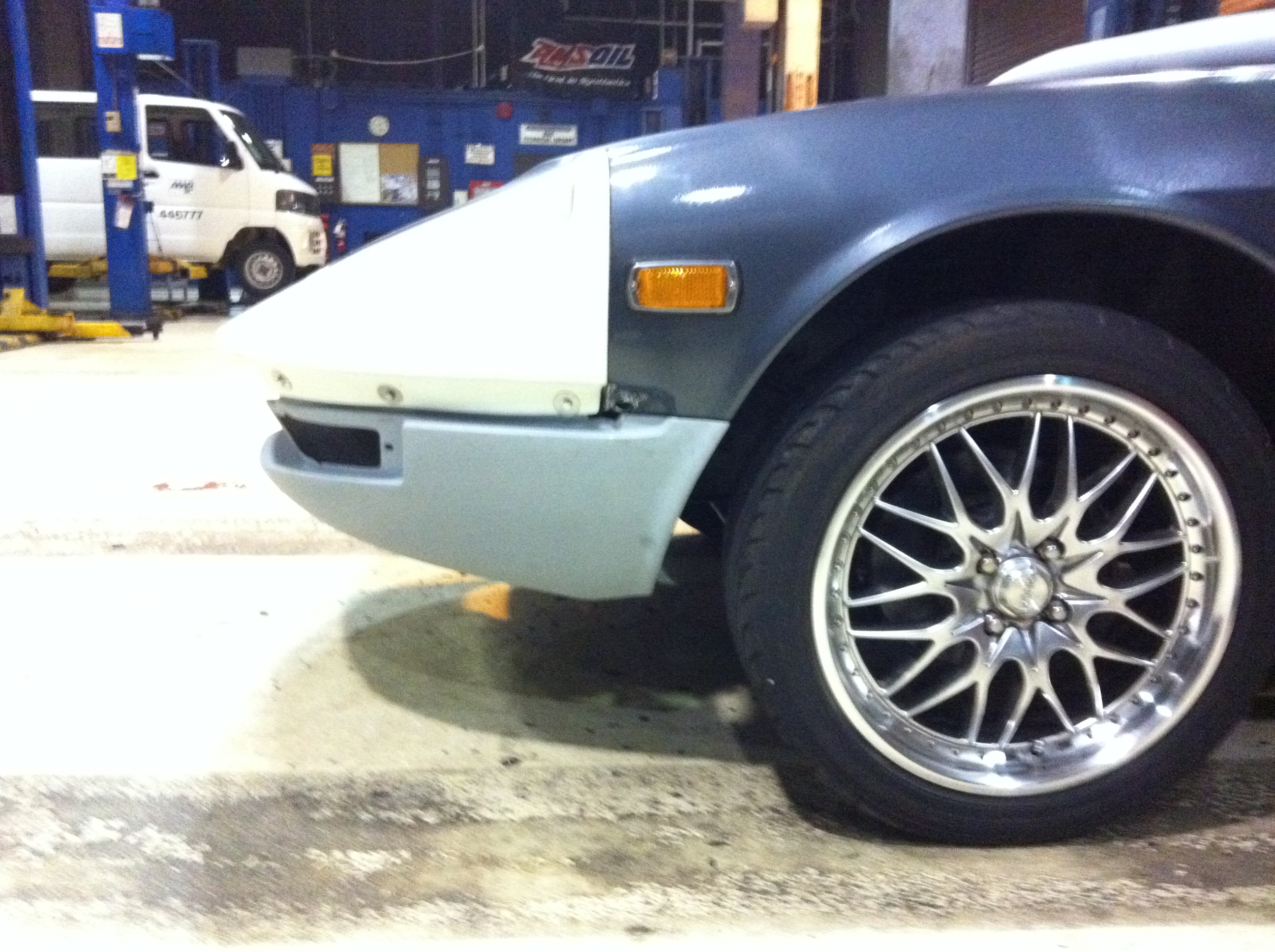
Just installed this last weekend. It is made in Hokkaido. The fit was pretty good except for the bumper, but not sure if that is because of those Black Dragon/Victoria British fenders that never seem to fit right.
http://home.att.ne.jp/sky/FairladyZ/
-
All,
This has been talked about many times, but still the answer still eludes me. Actually have spent the last few weeks reading endless old post on this and trying to find a way to get low and high. So, my apologies if there was a thread that breaks it down that I've missed.
I'm attempting to use the stock combo switch and EZ wiring harness but there is no intermittent relay. The following wires are coming straight from the motor, but which ones need what?
Blue w/red stripe going to a small relay on the gear housing
Blue w/white stripe that goes to a larger relay
Yellow that goes to both large and small relays
Black (that grounds to the casing)
Black that goes into the windings of the motor
Black that ALSO goes into the windings of the motor
Someone please break this down and help an electrical idiot out. How do I get power to the motor and two speeds? The Datsun wiring diagram doesn't explain what happens in the intermittent relay and that is where I get lost. So how does the 12 vdc get to the motor? And which wires get a ground from the combo switch to make Low and High?
Thanks,
Mark
-
It might have been me who you are referring to. I tried modifing Al's mount, but it ended up in the scrap metal bin. I used his design and built my own. This is the best pic I have of my mount.
There are a few more pics in that album.
I used the GT-40 intake which I believe to be 1" to 1-1/2" taller than Josh's Cobra intake. There are also pics of the header modification that was necessary for clearance. And I had to use a remote oil filter.
One last thing, Josh mentioned if you remove the hood latch you can move the motor further back. I don't "think" it is possible. My balancer sits about 1/2" above the rack and the front sump of my oil pan drops just behind the crossmember. What I am getting at is with the engine this low, you have to move it back until the oil pan can go behind the crossmember. With the engine that far back the top two bellhousing bolts are 1/2" or less to the firewall. If you use the original brake lines there will probably be interference, but I made all of my brake lines and just moved those two lines up about where the heater core bolts are and moved the proportion valve up and to the left side of the car.
One last thing, the shifter location for the T-5 is perfect!
Mark
-
Is that the same type bell housing that was used in the 94-95 cobras? It seems that I heard somewhere about a different bell housing during those years.
I used a World Class T-5 (which happened to be in my '86 donor car) and the JTR crossmember, hardest part was making blocks that follow the contour of the floorpan. Where my trans mount bolts up, the floor is not even.
Someone used the stock crossmember and bolted/welded new mounting points to the trans tunnel. I would have went that route if I hadn't already had my "blocks" welded up and drilled out. It was a good idea, hopefully someone else will remember who it was.
Mark
-
I used dynomax block huggers. Orignally, with alsil's mount they were fine. Because of the GT-40 intake I had to lower the engine about an inch or so and that made the header flanges hit on the tension rod mounts. Not sure if anyone else had that problem. I just cut the end off, welded a piece of 90 degree pipe, rewelded the flange on and here is what it looks like.
http://album.hybridz.org/showphoto.php?photo=1113&sort=1&cat=500&page=1
Hopefully, there will be no need to do what I had to.
-
Thanks guys,
I finally got a chance to update my photo album, check it out if you like.
http://album.hybridz.org/showgallery.php?cat=500&ppuser=8284&password
If anyone that is in the process of installing a 5.0, I do have pictures of the steering column and hyd slave cyl that may become handy. Just send me an e-mail at markam@myway.com and I can send some pics.
As for the block: After I put a set of after market heads on (est 325-375 hp), and replace the half shafts and welded diff that should brake. Then put a 150 shot or about 12 psi of super charger (est 375-450 hp), and replace the W/C T-5 which should be "all mushy inside" with a T-56. Then I will start shopping for that "sportsman" block. Meanwhile, to be on the safe side, I will put a girdle on it for a little added protection.
I dropped the car off in New Orleans on Jan 12 for it to be shipped to Yokohama, Japan. I have military orders to Atsugi, Japan.
BTW, I do have several videos of the car, one getting whooped by a '00 Formula Firebird (best et is 12.001 @ 119 mph) who is a buddy of mine. If anyone knows where I can post them for free, please let me know.
Mark
-
I had the one that was in my car when I bought it. I replaced it with a remanfactured on.
-
Great call. I replaced the booster today and everything works fine. Just got back from the first test drive. The brakes are not perfect, but I still have yet to adjust the proportion valve and bleed the entire system after reinstalling the MC.
Thanks for the help.
Mark
-
I know for sure that my rod has been pulled out several times by me, time to call NAPA. I did read some of the old post where that was mentioned but I don't remember if anyone said that that had caused their problem, unless I read over something. There is quite a few post where many others have the same complaint.
Other than having no pedal pressure, do you know if the full pressure is being applied to the rotors?
Thanks for your input.
Mark
-
Just wanted to let my fellow Blue Oval guys know that after 2 years 7 months, 16K plus in expended funds, 8 bags of sand, replacement body panels, paint, etc,etc, I finally started my engine.
It is a '86 GT "block", .030 over. PAW 347 stroker kit with Probe forged pistons. GT-40 intake, 65mm TB, 24lb injectors, and F303 cam (226 duration/ .512 lift). Centerforce pressure plate/clutch and WC T-5. Dynamax headers with 2-1/2" pipes into a Flowmaster 3" Y-pipe at the rear crossmember, don't have the 3" Flowmaster muffler mounted yet.
I used a wiring harness from Ryan McCormick ( http://fordfuelinjection.com/index.php?p=21 ) for the fuel injection, and I have to say that the quality is second to none. All connectors, the fuse block, and relays are high quality and it comes wrapped very nicely for a low price of $485. If you have the money and want a quality harness, look this guy up at http://fordfuelinjection.com/. He is a guru whith the EEC-IV.
The sad part is I still have the stock MAF, a Pro-M 75mm is on the way. The heads are stock (FOR NOW), I hoping Santa will bring me a set for X'mas, maybe Roush 180's.
What I can tell you is that the F303 cam is a monster! Espically with open 3" exhaust pipe turned down at rearend. The lope smoothes out about 1500 and then raps up to 4500 instantly. The computer still hasn't had any tuning and I have yet to see the check engine light after start-up.
Anyhow, just wanted to let you guys know. I will try to get some videos posted soon. I still have brake problems that are keeping me from driving it.
Mark
-
I have pumped up my brakes and bled them several times without the engine running, but when the engine is on the brake pedal has no feel to it. At first, the pedal would go all the way to the floor, so I done some searching and found many post of people that had the same problem. I went thru the rod adjusting, bench bleeding, and even the mityvac routines that others had recommended. When I adjusted the rod, the only change is that the pedal doesn't go to the floor now, it seems to stop about halfway.
I have the 4-runner kit in the front and the 240sx calipers/300zx rotor kit in the rear, both from Ross. A 280zx MC and Wilwood proportion valve. Every brake line, both hard and braided lines are new, so I gravity bled, bled and then used the mityvac to bleed atleast 10 resoviors of fluid.
Still, I can pump the brakes up and bleed them with the engine off but no pedal with the engine on. It does have pressure on the rotors when the engine is on, but I have no way to tell how much. I hope that someone can point out something that I have missed because this is the last hurdle (HOPEFULLY) before I can take that long awaited trip around the block.
Mark
-
I never would have thought that this problem is so common. I have a '77 parts car that I will check to see if it is toed in. Hopefully it is not and I can use the strut from it.
Thanks for the info.
Mark
-
I was using string to get a basic alignment so I could get my car to the alignment shop an found that my right rear tire is toed in about 1/2".
After looking for bent parts an checking that everything is tight, I can't find anything to explain why this tire is toed in.
Has anyone had experience or problems like this? I hope it will be an easy fix because I have to toe this car to VA this weekend.
Thanks in advance.
Mark
-
Thanks,
I was reading the instructions for the EFI harness that I should be receiving this month and do believe that it has connection to power the coil and relays for the fuel pump and computer. I will have to wait until I get that harness to know for sure.
Mark
-
I bought a harness from E Z Wiring and now trying to decipher the Datsun wiring diagram. The ignition switch has a black w/blue stripe wire that just disappears off the wiring diagram and I can't seem to find where it goes to. It is labeled "R" on the wirng diagram, does anyone happen to know where it goes? The wiring harness has five wires that goes to the ignition switch and the switch has five wires, I am not sure where this one wire goes. At first I thought it would go to the coil but the diagram shows it to be momentary when the key is in the start position.
BTW, it is a 5.0 engine and a GM colorcoded harness.
Thanks,
Mark
-
Thanks, that is easy. What wiring did you use for your car?
I bought a harness from E Z Wiring and now trying to decipher the Datsun wiring diagram. The ignition switch has a black w/blue stripe wire that just disappears off the wiring diagram and I can't seem to find where it goes to. Does anyone happen to know where it goes? The wiring harness has five wire that goes to the ignition switch and the switch has five wires, I am not sure where this one wire goes. I will post in the wiring section also.
I appreciate the help.
Mark
-
Can anyone who has used a factory ministarter from the late model 5.0 tell me how it is to be hooked up? It appears that it does away with the starter solonid that Ford used before. Does the battery cable hook directly to the starter and does the ignition start wire hook up to the ignition switch?
Mark
-
Here is a link to one of the many discussions about engine placement using the Ford EFI intake: http://hybridz.org/nuke/index.php?name=PNphpBB2&file=viewtopic&t=24881&postdays=0&postorder=asc&start=0
I had to change alsils mount to gain intake clearance because I used the GT-40 intake. If you are willing to use a cowl induction scoop you may be able to use alsils mount without modification. Either way you will have to add at least one U-joint, I had to add two.
Best advice is to read thru all the post in this section and a lot of your questions will be answered.
Mark
-
Someone posted a link to a company named E Z Wiring http://www.ezwiring.com/. From the pics it looks very similar to the painless kit and $100 cheaper, this is the one I am installing this month.
I also helped a friend wire an old Camaro with one of the painless kits, pretty straight forward.
Mark
-
That would work if I had a driveshaft and axles. Sorry for the deceiving photo. Here is one of the entire car.
I was hoping that someone knew for sure that that would be enough travel, or if someone knew the make and model of a car that has a bigger master cylinder.
Mark
-
I Installed a 7/8" pull type slave cylinder thru the hole in the bellhousing and installed a stock 5/8" MC. The travel of the clutch fork is just over the ".375" was written on one of the post I found from some time ago.
Can someone please verify that the clutch will disengage with only 3/8" of travel?
Here is a pic of my install:
-
Considering the $75 difference in the two setups and the holes drilled in the bellhousing, I will go with the ballpeen method.
Does everyone have this problem or is it because of the position of my engine/trans?


Complete SBF Conversion Kit
in Ford V8Z Tech Board
Posted
Ford Fans,
I agree that there doesn't necessarily need to be a book, just some thorough post with good pictures. Some pictures of my build are on My CarDomain page
There is a bit of info about my solution to the engine mount and steering shaft problems. Maybe this weekend I'll pull my engine mount out to replace the oil pan and if so, I'll take measurements in case anyone wants to copy it.
My EFI harness came from: RJM Injection Tech and it was very good quality. The wires were color coded and labeled to match ford diagrams. That was in 2004 and I haven’t dealt with him since; however, his website seems to have many more products than before.
For the drive shaft, it used a “swing joint†meaning that the cups were different sizes. Two were for the Mustang drive shaft and the other two fit the R200
Mark