

taylor76zharris
-
Posts
83 -
Joined
-
Last visited
Content Type
Profiles
Forums
Blogs
Events
Gallery
Downloads
Store
Posts posted by taylor76zharris
-
-
Alright ive been reading up on converting an f54, p90 head motor to a carb set up. Im unsure the differences in heads. I have read that the p79, p90, and p90a heads have the same valve size, combustion chambers, and intake runners. The exhaust ports differ from the p79 ( they have diamond shaped inserted exhaust runners) head to the p90, p90a. Is this true? Im wondering because i have read the p90 and p90a heads have larger combustion chamber because they were designed for the turbo motor.
-
What intake will work on the p90 head for carbs? Will the E88 intake fit the p90 head?
-
Alright will do. Thanks everyone! Hopefully ill be starting it tomorrow, with any luck.
-
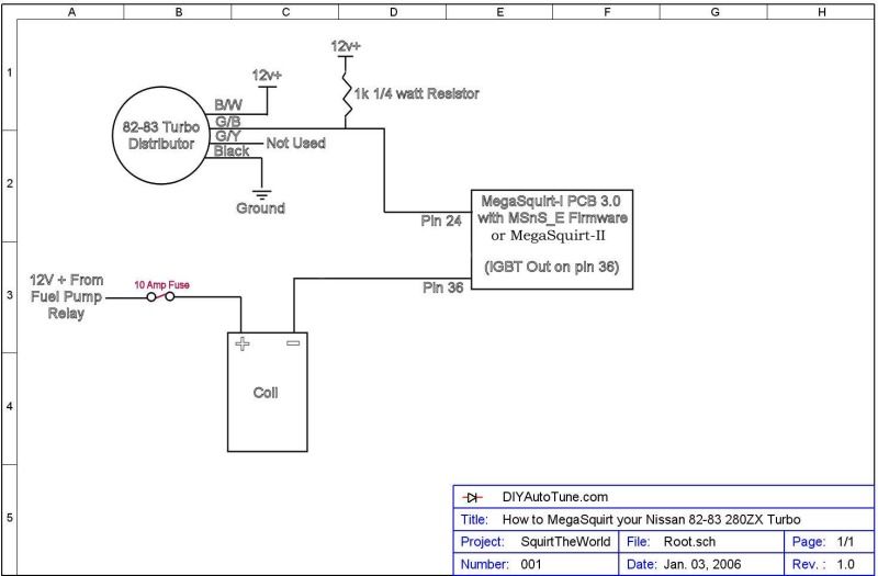
Ok, This is exactly how i have my board wired in minus the tach signal which has been giving me fits from day one, its just confusing to me because the ground and signal wire run in the same sheath and their twisted and foil protected and all that good stuff.
My questions/ can i run my sensor returns as shown in this diagram or does each sensor need to have its own separate return ground? Also, am i correct in thinking that the white tach signal is the only wire that gets connected to terminal 15 on the relay board? If so what do i do with the black wire that runs along side it? I have the black wire grounded through the distributor.

-
Thanks man, i hope so. This is my third complete re-wiring of the whole thing and hopefully its the charm. Not that ill be much help but when is it misfiring, at idle, full boost, or in between?
-
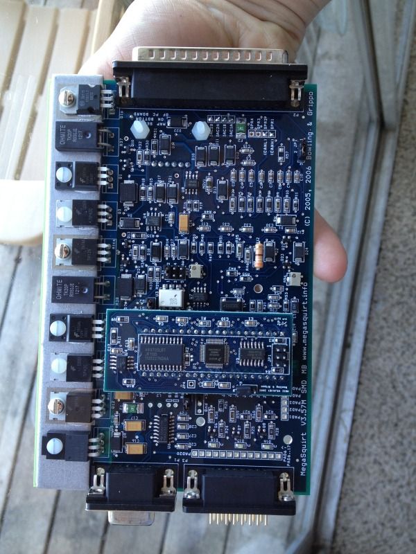
Awesome thanks! I tried to do my best to get away from any interference with the distributor wire but I understand Noise is a pretty common problem with this type of it install. I hope I get lucky and don't have any but I'm not counting on it. 1 last question on the relay board there is a large port for an engine ground will that take the place of the 5 ground wires in the DIY wire harness? Because I noticed when looking at pictures and when doing some research no 1 has the 5 wires anywhere on the relay board
-
Oh alright. So could i use one of those pins for the green/black wire on the distributor that has the pull up resistor in line?
-
I'm reaching the end of my megasquirt install but I've hit a snag. Where is the best place to tap 12 volts for the injectors and for the distributor? I don't want to source 12 volts for them all from the same place and I don't think that's how it should be done but I'm no expert. Also I'm also doing the install with a relay board from DIY autotune. So where's the best place to get 12 volts for the distributor and the injectors and how many times can I tap the same wire for 12 volt? Thank you.
-
No, i really don't know why it burnt up like that. Im sure i just had some wires mixed up. This is my first attempt at such an in-depth wiring job so i was expecting a few mistakes just nothing this serious
-
Im just wanting to know if this can be saved. Its never run on a car but this happened as soon as i turned on the ignition.
Has anyone ever been able to use a board that has this amount of damage? I know you cant tell if something is burnt internally and neither can i. Any help would be great, Thanks, Taylor.
-
Thats just how i have it. I think im going to rewire it using the relay board form diy. Hopefully that will help sort out some of my wiring issues.
-
I did the tests a few weeks ago and everything checked out. However, i need to make sure i have 12v while cranking.
How is your coil wired up? if youre using just a single coil that is.
-
Great thanks for the info! Its nice to know my settings a right or at least close to it.
I made the changes you recommended but still no spark.
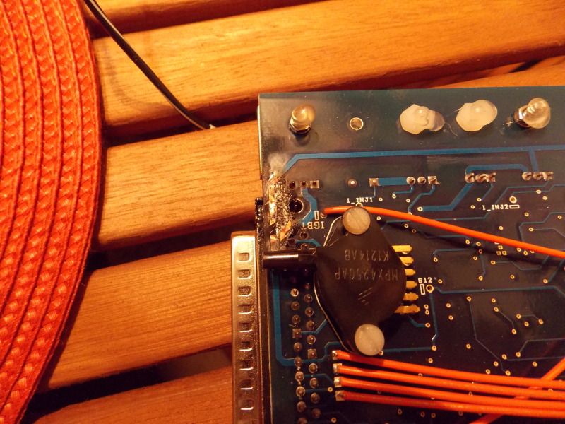
I did some testing and i think the reason my board burnt right there has something to do with the coil wiring. I disconnected the 12v+ at the coil and watched the for smoke and/or arcing on the board (i had the cover off) and saw none. When i reconnected the 12v+ and turned the ignition on there was a faint spark off of the outer-most exposed circuit in the picture. I dont know how to fix this because the 12v i used for the + on the coil came from the fuel pump relay.
-
Ok we will see if it works. Here is my msq.
Let me know if it worked, Thanks
-
The coil needs to have current flowing through it to work. It fires when the current is interrupted. You can have voltage but no current flow. Follow the circuit from the power supply, through the coil, and to wherever the circuit making and breaking hardware is (BIP373 probably, inyour case). The ignitor would do that job in the stock system, at the control of the ECU. The BIP373 transistor in MS should be doing that job now. If it's connected correctly, then the next thing to look at would be the signal that the ECU uses to control BIP373, probably the CAS.
Power+ > coil + > coil windings > coil - > BIP337 > ground
BIP337 grounds the circuit when the ECU controls it to do so.
Thats onething i havent been able to check because im usualy working on the car alone. Ill have a friend there to help tomorrow.
And yes i am using the BIP373 to control spark. If im getting an RPM signal could me CAS still be wired wrong?
You have to place your current MSQ in a "zip" folder and then upload the zip folder. Just right click on your desktop. Create new zip folder. Drag your MSQ into that folder and upload it here.
Did you get a new board too? Previously in the thread it appeared your board had a burnt spot on Q16 underneath?
Get that msq uploaded and maybe a data log cranking the car a few seconds.
Alright thanks! Ill get it uploaded as soon as i can. Hopefully later tonight.
Well it turned out that i didnt burn it up that bad, just some insolation on the board but every thing seemed to still work. However today when i connected the megasquirt to the harness and turned the ignition on the same place started to get so hot that it melted off more on the insolation but all the wires are still in good condition. I didnt even crank it before i noticed smoke. what could be wired wrong to cause this? Here is a picture, BIP373 is just to the upper right of the burnt spot.
-
I have been checking both places, coil and plugs. I even bought a new coil thinking that might be the issue. The ignitor on the coil bracket, i have nothing wired to it. i didnt think it was used
-
Could i just take a screenshot of all my tuning tables open? I cant seem to get the msq to upload
-
Ill have to upload my msq file a little later. Im having trouble getting it to work. Here are some pictures though. Hopefully you can read everything.
-
I do now yes, just at 200 RPM. I still have no spark.
Im pretty sure everything is set how it should be. Im using direct coil control and my board is set up with all the proper jumpers per DIYautotune for direct coil control.
All that can leave is the coil, ive got the +12v and the - to pin 36. the coil is getting power however, megasquirt isnt able to finish the circuit somewhere and release a charge.
-
Alright awesome. There were a few things i overlooked the first go of this install, so i think ive got everthing corrected.
one thing that is concerning to me now is wiring the 12v drop resistor. I dont want to splice into the wire because i dont want to chance it shorting on the shielding or another wire in the shroud. Whats the best way to go about wiring it in? Where should i connect it?
Thanks.
-
lol. I hope mine did!
Alright ive almost got it all wired in again but one thing i noticed is on the megasquirt unit there is a bar map sensor inside. Do i connect a vacuum line to it? I did not realize this the first install but it has a nipple on it and theres a hole on the side of the megasquirt ecu.
-
Okay, i think mine was set at 9 for some reason.
Yeah i was getting an rpm signal when i was cranking and i know i had fuel. The coil just wasnt releasing a spark i think, even though it had power to it.
I really need to get the system wired back in the car. Ive learned all on here in the off season.
-
okay. Ive been doing lots of reading on drop resistors latley and i think im finally understanding what there for. Yes, it was set on going high inverted but my dwell setting may have been wrong. What should my dwell be set at? Im using the stock coil and a stock 83 turbo dizzy.
I cant remember what my dwell was set at, its been so long.
-
I was confused on this a bit. B/W and G/B both have a 12v supply but the G/B wires 12v supply has a 1k 1/4 watt resistor in it? Why is this needed?


Need to clarify some head facts
in Nissan L6 Forum
Posted
Okay thats what i thought