

nash542001
-
Posts
75 -
Joined
-
Last visited
Content Type
Profiles
Forums
Blogs
Events
Gallery
Downloads
Store
Posts posted by nash542001
-
-
Nevermind file size is to largeHere is my setup.
-
Here is my setup.
-
Thanks, I will have to measure to see if they will work. Not cheap indeed.
-
So where did you find one at?
-
Does any body know the distance measured from the block to the first rib on the crank pulley for the serpentine belt? Trying to make sure the balancer is seated correctly and it looks to be too far out. I don't have the alternator bracket installed to check the alignment because it is are on order. This for a f-body accessory drive setup.
-
Did you try using a screwdriver through the timing gear to lever it up on the cam with the chain on the original link mark? From the picture on the timing marks the grove looks like it might be a little to far to the right, i.e. one tooth off. The "v" notch should just be off to the right with the edges of the notch and groove lining up or maybe over lapping just a little. It has been a while since I did mine, but that is the way I remember it and the manual's picture is the same way. Then again the could be slack and stretch from it being an old chain, but I would think the notch would go more to the left as the chain stretched because the time to change the positions (i.e. advance) the gear is when the notch is to the left of the oblong grove.
-
I checked the manual and the notch "v" should be on the right side of the oblong grove in the locating plate. The chain should have 42 links between the timing marks on the chain, but that can't be verified with out taking the cover off. You should not have to check that unless you dropped the chain. If the notch is off the left side of the oblong grove you will have to use higher number position on the cam gear.
-
The cam gear has 3 different positions with 3 different timing marks. I would use the mark that allowed the gear to be installed with the oblong grove on the locating plate just to the right of the "v" on the cam gear. The cam can be moved just as long as the timing marks line up on the gear and chain properly when installed. If you drop the chain or loose slack on the bottom/crank gear, your screwed and have to take the timing cover off to verify the bottom link/mark. This is from memory and should be verified by the manual before taking my word for it.
-
It should work with the shifter at the rear position and the engine as close as you can get it to the firewall. The T-56 magnum dimensions are given on SilverSportTransmissions website http://shiftsst.com/store/transmissions/t56-magnum. Then add the length of the bell housing (approx. 5.6") and compare it to the length of the original transmission (29" to shifter) minus the difference in how far back the two engines sit.
-
You should not have to do anything with the ducting besides just taking the box that holds the evaporator coil apart and taking it out. The box should be put back empty. I just made a cover plate for the holes in the firewall and kept the heater for the winter.
-
Ok, so I can test the breakaway away on this type of LSD like the clutch type. I thought the helical was different and would not be able to test that way. If it acts the same as a clutch type in operation I will be fine and check it the way JMortensen describe. I just wasn't sure on exactly how it could be tested for correct operation before install. I will try that as soon as I get a chance.
-
Define what type/size of lever. I do not have any special setup nor have it where I can put on a wheel for more leverage. It is just me turning by hand with axles in the sides. I at least thought they would turn in both directions, but not none at all.
-
It spins freely with all the washers out and with 0.5 turn preload it is a little harder to turn, but with 1.0-1.5 preload the whole thing is lock up solid neither side will spin just the whole diff.
-
I set the preload on the OBX like RYbrant's website said with 1 to 1.5 turns till the cases are fully clamped, but then it acts like a solid diff when I try to put an axle in it and turn them. Is that how it should be or did I do something wrong?
-
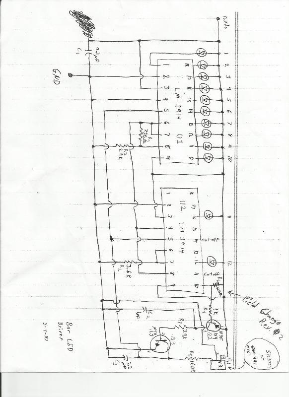
 Here is the schematic revised, as I said earlier that to use this you need to jumper out the old flasher and add in two for the front after the power for the signal splits off to the rear. Of course that is assuming that you are using this circuit for the rear.
-
Well the fixed worked. I will be ordering and making some boards for this circuit. Also I am trying to make my own cast lenses like the ones on the car. If I get the process down with no problems I will make some extras to sell at a decent price.
-
Nope, just making them for myself right now. If I get to where making them is less time consuming then I might decide to sell some. Will not be anytime soon.
-
I think I found the way to fix the voltage fluctuation and cycle disruption. I will post my findings when I try the fix out.
-
I researched this too when rebuilding my engine and came up with the same conclusion. Wider gap on the 2nd compression ring. So I gapped according to the new school. Did not have a baseline to compare to though. Talked to a pro-drag guy who knew his stuff and he said it was better, but said that they would drill a small hole in the top of the piston and have the gasses come out the top ring land, I think it was called gas porting but this is said only to be effective above 7000rpm.
-
-
If you are using megasquirt then you could use a tps from a kia. I think it fits the shaft of the nissan throttle body, can't remember if I modified it any, but you would have to design a mounting plate becuase the mounting holes are not the same. I used one like this http://www.ebay.com/itm/Standard-Motor-Products-TH366-Throttle-Position-Sensor-/230900711053?pt=Motors_Car_Truck_Parts_Accessories&fits=Make%3AKia&hash=item35c2c13e8d&vxp=mtr. Has worked fine for 2 years now.
-
Not a transformer, but a voltage regulator or resistor to drop the voltage down. This would all depend on how many LEDs you have in series and rows in parallel.
-
Check out the group buy forum and search for turbo manifold, you will find alot of useful info and pictures.
-
http://forums.hybrid...running-lenses/
Did you mean clear with no pigment or clear with no distortion? The hard part would be making casts without the distortion caused by all the little dimples.
Your datsun Z's turbo'd "LS" engine pictures
in Gen III & IV Chevy V8Z Tech Board
Posted
Finally figured how to upload it.