
280zzzzz
-
Posts
28 -
Joined
-
Last visited
-
Days Won
1
Content Type
Profiles
Forums
Blogs
Events
Gallery
Downloads
Store
Posts posted by 280zzzzz
-
-
Aug 76 280Z - Car runs good, stock chassis wiring.
Voltage Gauge stopped working, any trouble shooting tips will be appreciated.
Gauge tests OK...
-
She is an Aug 76 serial number
I've owned it since 78ish It has always work until now.
I do suspect the voltage reg 7pin connector -
Time to get back in there...
Thanks for the comments.
-
 1
1
-
-
Is it from old (unused) fuel Injection computer?
-
I wanted to post a Thank You to all those who have contributed their expertise about trouble shooting the Dead Light Syndrome on Z Cars.
You know who you are. I'll share my experience - Hopefully it will help someone else.
I have gradually been losing electrical component functions. Last week she stopped charging while cruising around. Voltage gauge gradually dropped to 10-8-6 volts.. Thankfully I have an Optima Yellow top and was able to limp back to the shop. This car has voltage regulator separate from the alternator, under the fusible link/beer can holder. With battery disconnected, I was able to confirm alternator was not charging - by cleaning the 7pin connector at the regulator - 1 pin showed only minor corrosion; This was enough to regain charging, and has been charging/starting since. I regained tach/gauges also.
Now, on to the dead headlights + hi beam indicator / exterior signals + dash indicators / emergency flashers & brake lights - So, undrivable.
Following the suggested troubleshooting recommendations in the forum, I confirmed continuity and cleaned all fusible links and fuses, all good - some minor overheating indicated on front right (heaviest) fusible link. Test light confirmed good power at all fusible links and fuses except the headlight fuses.
I moved on to checking grounds, dremmel wire brushed license plate and headlight ground connections, did not look too great- paint from body shop on connectors, especially at the rear, reconnected with some dielectric grease.
Then on to the flasher unit above hood release, found that the 2pin L-Shaped plug had become disconnected.
On to headlight combination switch, removed shroud,
(this reminds me of the Japanese sense of humor - 6 screws - 4 different types / take note of what goes where)
Found out why my horn doesn't work - broken plastic connector on thin brass brass horn connector. Taped it up, out of the way.
Searched around for loose ground, or other obvious issues - none seen.
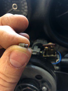
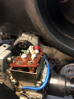
Sprayed some Deoxit chem spray around the hi-beam lever, turn signal cancel mechanism, and in and around the little circuit board in the pictures below...
As I was test probing for power around the Green - Red & White Red Wires attached to it, and moving hi-beam lever, cycling on/off the headlights
VIOLA!?!!?!? On came my Headlights, Low&Hi Beams! & Signals!! Interior indicators too!?
So with this progress, I remember reading that the 4 tabs on this little box can be carefully straightened upwards to access the parts inside.
So with battery once again disconnected, I opened it up to find an old school switch mechanism, surprisingly with NO visible corrosion or signs or arcing or overheating. Rotating the headlight switch moves two little nipple like pieces - I thought i would run a bit of sandclothe over them (don't do this) I thought I had broken the little tit off! But then realized that they are little caps, supported by tiny little springs. I very slightly pulled on the springs to provide a bit more pressure on the little brass contact levers also contained within, sprayed some more Deoxit around and cleaned all the parts with a cuetip. Reattached the small brass tabs -
I know - long winded // Really just a sincere Thank You for all the guidance.
PS: Now my Volt gauge doesn't work. LOL - any ideas???

-
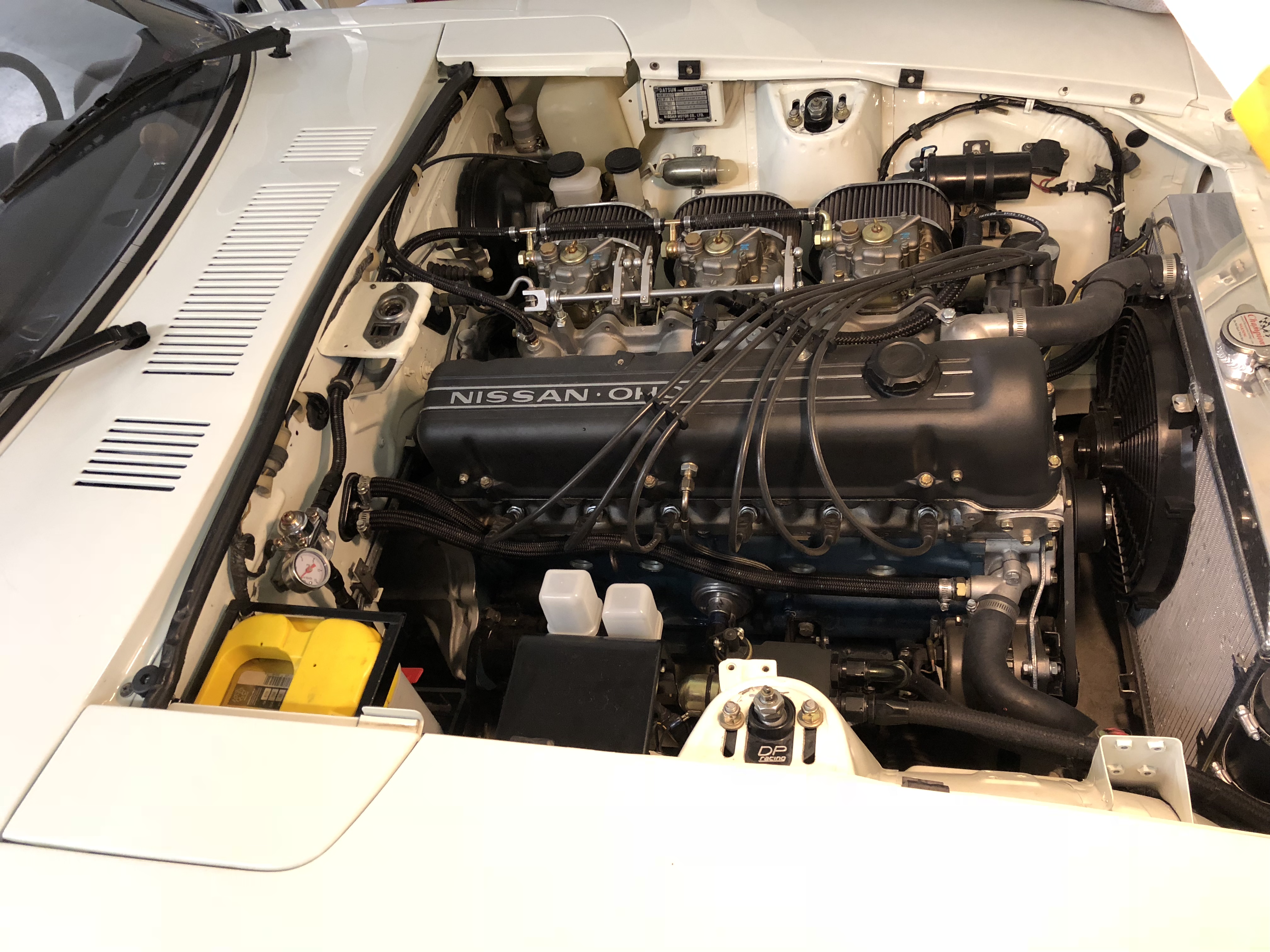
Have not regretted this for a moment - Expensive though... Aug '76 359550 280 bored - stroked - 10.5/1 New (Spanish) Webers 44 s
Remove: fuel pump - pulse dampener - filter - all fuel distribution lines in engine bay - bosch FI computer and harness at LH footwell -
Retain: Steel back to front fuel line.
Unused: Fuel return line (cap off)
New: Fuel Pump - buy a good quite low pressure unit... / Wiring ( with some form of auto shut-off, in the event of an accident ) - fuel filter - pressure regulator -
engine bay braided hose & AN fittings for distribution to banjo fittings - Webers - rebuilt and cleaned - even new ones - the correct size for your specific engine build - linkage mechanisms - velocity stacks - air filter (s) - header heat shield -
- an old Weber expert for tuning...
-
FWIW.
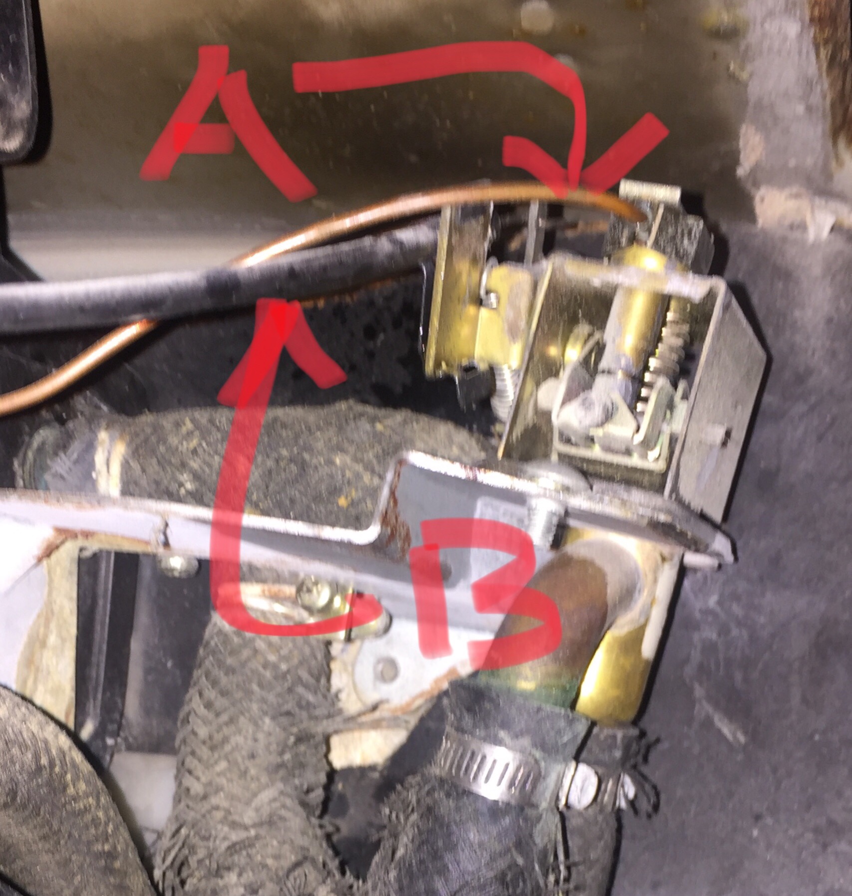
On 350559 August 1976 280z
Interior heater water control valve is actuated with copper capillary “A” & “B” sleeved control rod connected to the TEMP -COLD/HOT lever.
No vacuum activation on these late models.
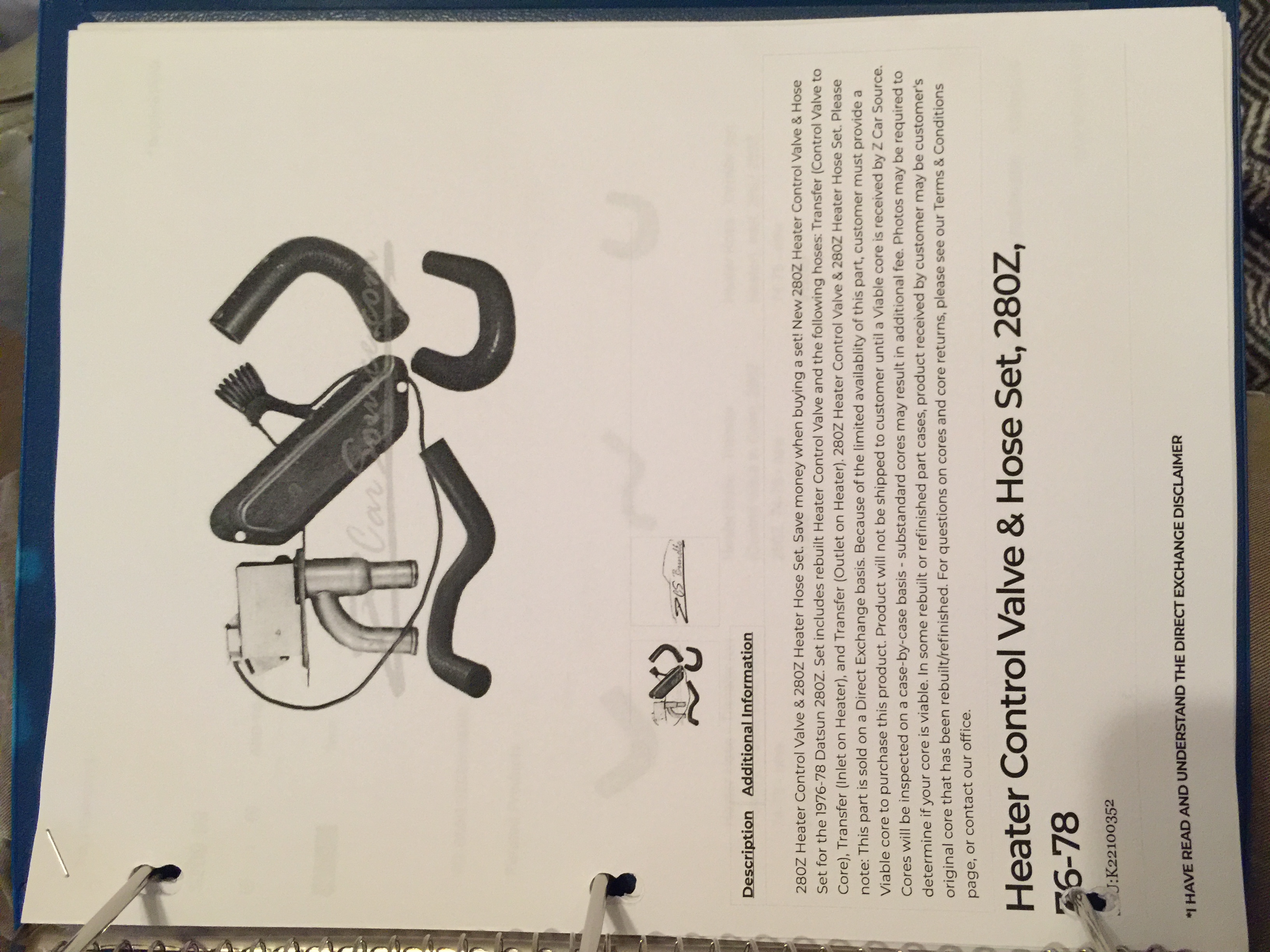
ZCar Source currently has a package SKU:K22100352
It includes the 3 hoses, and
(core swap exchange)
control valve c/w capillary tube and temp sensing unit.
-
This summer I had an antifreeze geyser in my passenger side footwell;
GF was NOT impressed 8)~~ I bypassed coolant lines to heater core in engine bay as a patch.
Looking in the Service and other Manuals, and various forums, I believe this (heater) system
for these years,can be repaired, without removing the dash. Although some say that it is quite a pain in the back - literally.
As with all things Z - there are quite a few "improvements" based on date code - I am 359550 Aug '76,
and my heater control valve/air control doors are control rod controlled only - Not vacuum.
It sounds like your issue may be seized, bent, broken or disconnected control cables, or a failed control valve,
or malfunctioning airflow transfer doors.
I'll be disassembling mine over the weekend, and may have some pictures, better info next week.
-
Get the seats first; If you"re 6'3 test your but in the seats you are thinking of,
alot of them are VERY narrow. You will find that the big tunnel bumpout, will be where most of your work will be concentrated.
In order to get the seat low enough - and toward the center of the car... So the door will close..
If I was doing it again I think I would cut that whole shaped section out, and replace it with flat material.
-
Thanks very much for the feedback Grannyknot -
I'm thinking of ITG Filter over velocity horns - I guess I could vent it into the backing plate of the filter .... ?
-
I am working on my Aug 76 280Z, using stock cleaned up fuel tank
I have not posted much here lately, but would appreciate your opinions on whether or not
to retain vapor tank in a swap from Bosch FI to Carbs.
I have a NA Stroked L28 with 45 Webers, and am using a low pressure fuel pump from
an older RX7 and plan to run it without a return line.
My thought is to vent the tank to the fuel filler neck - What has been the most successful approach?
Thanks in advance for your thoughts.
-
Does anyone have experience with the spook for 280z. Pictures?
How does it look? Installation difficulties?
-
Thanks all.
HybridZ. XLNT Resource as usual!
-
Does anyone have a "license plate" center trim panel with light for a 1978 280z
The body shop "can't find" the one that was one there when they took it apart.
OO
~~~
-
The bolt ons' do look nice on top...
These DP units look about the same either way. I think it turned out pretty clean - I stressed out for the longest time about cutting into the towers...
I would not have cut them if the car had been perfect in every other way...
My MO is function first - it made sense to mount them below.
Welding overhead does tend to markup my nice helmet... I appreciate your comments Mort.
-
Front Camber Plate Installation Experience.
I obsessed about the installation of my front plates for...... a long time.
I ran with stock - mounting insulators / bearings with GC coil overs / sectioned struts / Koni 8710 - until adding the DP Racing plates.
With front fenders off, and struts removed, I measured / marked the c/l of strut to firewall distance using a piece of stainless steel as a straight edge between the two strut towers.
I used a large blob of plumbers putty jammed up into the strut tower to use as a pattern to form the outside shape and bend angle required for the camber plate. I then used the plate as a pattern to mark the top of the tower leaving 1/4" to weld the plate to.
At this point I secured a piece of 1" plywood under the strut tower through the three mounting insulator attachment bolt holes - this wood was used to center the pilot bit of a 3 1/2" metal cutting hole saw, driven with a Hole Hawg. This was the perfect size for the inside cut on the top of the tower, only three straight cuts with a zip grinder finished off the strut tower top modifications.
After metal prepping the under side of the strut towers, aligning them, the camber plates where welded to the bottom of the towers.
I know - long winded... I hope this helps someone through this process.
I have wondered why I don't see more camber plates installed BELOW the top of the strut tower, since the forces will be up against the underside of the tower, rather than being resisted just by the weld when mounted above. - Also the PillowBall flat surface mates nicely against the underside of the camber plate without any interference with the cut surfaces of the strut tower, which sometimes happens when the plate is mounted on top.
A couple other things that where required... The top of the Koni damper rod required some machining in order to fit the sleeve in the PillowBall -- Also the top nut for the damper rod required a little machining in order to fit the top of the PillowBall. Thanks Andy.
-
I have had a similar issue with an Aug 76 280Z.
There were production changes all the way along -
Don't worry too much about MR.P.Eng -
I feel the The serial number is the determining factor.
Black Dragon has some good info on the website.
-
can you get a USPS Ground Service Rate quote to V3S5T1 Surrey BC Canada and I'll send PayPal cash - if that works for you.
-
Looking for 240 & 260 or 280Z front grilles - to fill in lower opening on 280Z with 240 bumpers.
-
atlanticZ.ca - Z Tech Tips/Electrical Good Info source
-
Thanks for the offer Zentech -
And for the excellent crossmember z240, she's been through garnet blast and is over at powder coating now.
While rebuilding my front suspension and replacing bushings ,sway bar- I noticed that the crossmember had taken a pretty good shunt - and was a bit wadded up. So while I'm waiting for engine to come back from the shop, I thought I'de take this step to get the front end back into shape.
Thanks Again Jim - I appreciate you help with this.
-
The strut tubes on 280s are larger diameter, thicker material and also longer in the rear. It always amazes me how much the bumpers, rubber bits,filler trim, bumper shocks and fluid, brackets, and all the bolts weight, on the big park bench bumper system.
-
TimZ - Ya - No. stud can not be removed
-
Thank s Calgary - This pump outlet fitting is configured M12-P1 male stud - like a "bolt" with the discharge in the center. I would like to use banjo style connection - I need to adapt from male to female threads... I can't find any fittings with M12 fine P1 pitch threads. It is so strange that they would provide pump w/ Ba$%#d connection size : ] I've tried hydraulic - diesel - auto supply houses, Might be time for gear clamps....
-
Thanks Beerman Cheers!

280 Volt Gauge Trouble Shooting
in Miscellaneous Tech
Posted
Thanks Guys - Ya time to roll up sleeves and get in there...FSM in one hand... and translator from the humorist who wrote the manual to english in the other...