
OlderThanMe
-
Posts
3005 -
Joined
-
Last visited
-
Days Won
2
Content Type
Profiles
Forums
Blogs
Events
Gallery
Downloads
Store
Posts posted by OlderThanMe
-
-
In March 2010, I designed an L4 shortblock using some off the shelf 86mm pistons, 96mm throw crank, 152.5mm (6")rods.
Finding 6" rods is "impossible" so I shelved the idea.
Bought myself the lightest weight Datsun I could find, a 1981 Datsun 210 with a 40RWHP A14 engine and a 4 linked 3.90:1 H145 rear end. Car has a basically damage and rust free chassis(other than some slight hail damage on the roof and slight rust on the bottom of the doors but it is 8000X better than my 260Z was.
Owner said it was running but when I got there it would turn over and cough but not start. Gave $640 for the car since it was rust and damage free as far as I was concerned. Got it running with a shot of carb cleaner in the vent tube of the nikki carb and I am enjoying the 32-35mpg that the car offers.

paint polished up pretty well(I'm a race car technician, hence the vehicle in the background)
First upgrades/modifications
new complete clutch kit: $53
Sylvania silverstar headlights: $40
240Z taillights nearly fit into the stock taillight holes so they are put in(still need to be properly mounted...
I just spliced the 240Z taillight harness with the stock 210 harness to adapt it to the stock 210 body harness.
1g talon seats mounted basically to the floor
280zx Iron cross wheels with 185/65R14 Douglas all season tires.
Found myself with a Z20E with the good rods and bought all the other stuff I needed to assemble the shortblock.
deburred and smoothed the interior of the block(~30 hours of work with as many different carbide bits as I needed)
before:
deburred the main caps too
block back from the machine shop
painted
main studs
bottom end components ready for assembly(200+ hours later)
wrist pins installed with lock rings
bottom end together
nothing really special about this engine build....just a typical off the shelf bottom end that should be good for setting up the top end stuff.
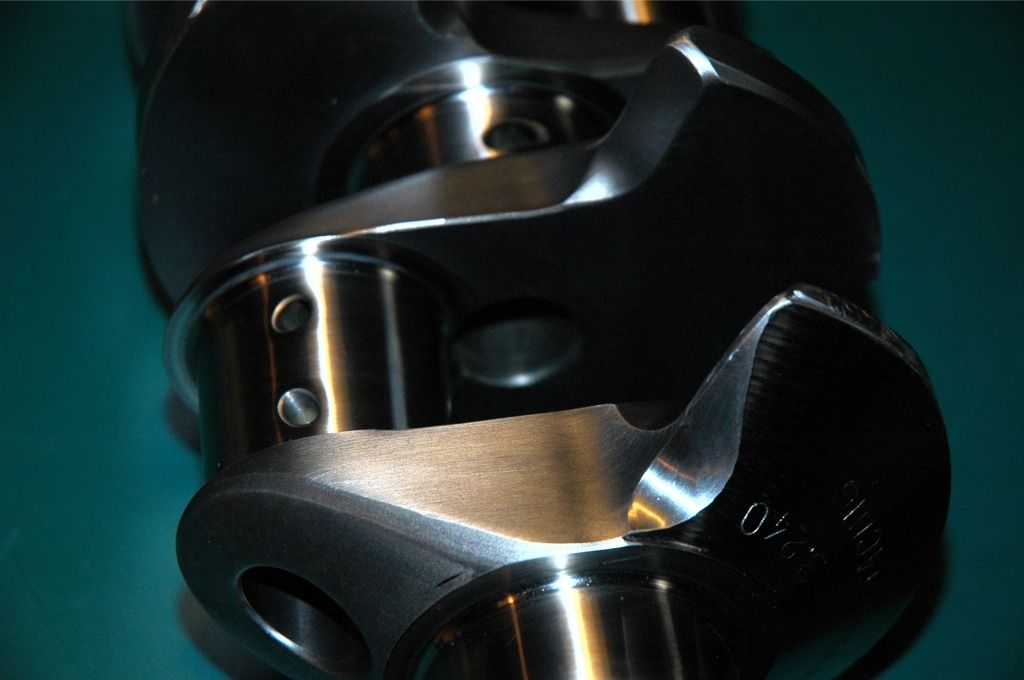
something stupid I bought.
Something stupid I built out of OEM Nissan parts but I doubt I'm going to use it... you can see 60% of the back of the valve just looking through the wide open 45mm throttle plate.
-
Almost makes you think the second one would work, doesn't it?
-
Quick question though... in your picture there's quite a bit of material from the main journal in the critical plane. Am I wrong? Is this being calculated? Are you cheating me?
Nope. The critical plane contacts the main and rod journals at one point each. Also mind you that I have 34mm for each cheek pad. Yours look offset to one side with different cheek pads. (I'm hoping that your motor is based like that)
It also looks like you cut into the main and rod journals too with your critical plane? What are the rounded parts at the upper and lower portions? Are they radii on the journal?
OTM
-
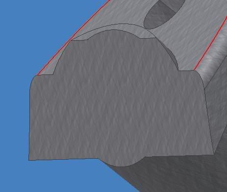
OTM Here's a cut like you were saying.
Inventor is calculating an area on this plane of 1503mm^2, which is 59.1732 square inches.
Alright... now lets get rid of any stress risers(sharp corners...) and then maximize your critical section area. Use that information I gave you and plug some numbers to figure out if it will hold up to your expected horsepower levels.
Although 59in^2 sounds like you had an error somewhere in your conversion math. 6"X6" only yields an area of 36in^2 and your cross section isn't that big.
Just as a comparison, my design has a cross section of 2249.2mm^2.
-
Proxlamus posted this link in his ITB fabrication thread...
http://www.velocity-of-sound.com/velocity_of_sound/calculator3.htm
-
OMG Tim!!!! lol
Gollum, for a N/A motor, long nuners are good for torque. Have you figured out the helmholtz numbers for your peak pressure?
It wouldn't be that hard to make a variable intake with a design like that........ two plenums etc...
-
I had a time doing this on an LD28....
I stripped everything off the motor down to the shortblock with the pan off(the world's nastiest black mess). I then crammed a wooden hammer handle in behind the #1 connecting rod and proceded to snap the hammer in two. Then I got a 2" diameter pine dowel and crammed it in there. With a cheater & breaker bar I was able to release the bolt. It still destroyed the dowel...
Be sure to use a soft dowel as not to marr any internal parts.
I've pulled an L24 apart in a matter of about 60 minutes to get the rods in a JY(motor still in car) but that LD28 took 3 days to pull apart on an engine stand!!!!
-
yes i want to mount both its an original (as they get) aluminum louvers that fit out side the window and the spoiler is the 1 piece fiberglass that is the most common one.
I have no hinges or hardware so if i see a close up picture of how they mount i can make something up or get hinges from the hardware store.
Thanks
Nick
First of all, Is this on an S30, S130, or Z31? I'll assume S30.
Philbert, I do not believe that any Z car came from the factory with louvers. I suppose it may have been a dealer option somewhere, but not factory.
I'll try to find a pic of how the louvers were setup on my Z. I still have the hatch so I can get pics of the 8 hole locations.
-
The other day I was driving to school with the windows down in my truck.....
My right hand was on my thigh and I begin to feel something. Next thing I know a yellowjacket crammed his stinger into my fingernail and slid along until he rammed it into the quick of my thumbnail. I flung it into the cupholder and crammed a Dairy Queen cup on top of it to restrain it as it had not completely died from my attacks.
It may only be one little yellowjacket, but it freaking hurt more than most any other sting I've had.
OTM
-
-
banana's actually make me sick. the scent of them is enough to make me nauseated and gag
Your not alone there...lol
-
The SHO engine isn't a ford engine, it's a Yamaha engine
I second that!
-
How come EVERYTHING is in Stone Mountain, Ga? lol!
The city is a whole 1.3 square miles.(10 miles from me)
-
LD28 intakes are around 34-36mm(mostly 36mm) and it could be adapted pretty easily if you want to go that route.
-
Its a rendering that I made the other day.
I want to learn more of the animation stuff but I still stink at it. lol
-
Gollum,
Have you measured your critical area in your crankshaft?
Its from the bottom of the rod journal to the top of the main journal. The max stress of the crankshaft moves through this plane.
ala critical plane:
OTM
-
Thats awesome sounding with the inserts in the exhaust. Imagine what it could do with some upgraded camshafts!!!
Sounds wicked.
-
Anybody know an exact figure on the angle of the valves on an L head?
My rough measurements were came up around 14 or 15 degrees but I want some solid numbers.
-
The problem isn't finding someone to make the crank, the only problem is finishing a crankshaft design and sending it to your choice crankshaft manufacturer.
And about $2000-$3500 depending on your crankshaft design and how intricate it is.
-
Instead of leaning the valves over why not just raise the ports up? It seems much easier to mess with ports than to mess with valvetrain geometry.
-
Well I've seen a couple oil pan drain plugs that have the magnets on them. Really helps keep crud out of the oil if you are munching something in the motor.
I suppose you could epoxy a rare earth magnet to the fill plug if you can't find the particular plug.
L6 drain plugs have a M16.4-1.33 thread(SAE?) with a 21mm head if that helps looking for a generic part.
-
Oh and also Question for OTM, who seems like the person to ask right now.
Does the rod bearing being closer to the main bearing cause more load on the main bearing leading to more severe wear?
It seems like the rod will be pushing very directly on the crankshaft and be putting a lot more force on those bearings. If so, much larger main bearings might be REQUIRED, and might rule out many block options as custom bearing sizes would be required.
I could be wrong, please say so.
You are almost there, but 180 degrees in the wrong direction.
The more the rod journal and main journal overlap, the more rotational strength there will be.
Severe bearing wear is more related to counterweight than stroke, but it does have some effect.
Think of it as a simple beam problem rather than a complex crankshaft, just for a minute. Think of a pair of beams joined t look like a "T". The top part is at the centerline of the crankshaft and the vertical part represents the stroke.
For the same amount of force applied to the bottom of the vertical element of the T, a shorter vertical element will apply less twisting forces on the horizontal element.
What I was saying about bearing journal overlap is that the more solid metal that runs the length of the crankshaft, the more stout the crankshaft is, thus improving crankshaft lifespan and less axial twisting.(thus bearing wear too)
A ballpark figure for the amount of twist in a crankshaft while running is around .03 degrees.
-
whats wrong with doing the in-line lower intake on the vh, like the blue dett vh 240z, just need 2 sets of stock parts!!!!
why bother with custom machined items when the stockers are ideal???
just clean up the casting flashing and youre 98% ther to what has been drawn in solid works!!!!
my 26.3 c worth, what can i say its been a while.
nat0
I have all of the parts to put that setup together, and have assembled it on the engine once.
Mind you that its not 100% bolt on but you have to grind some tabs off of the runners for it to fit but other than that it is easy.
-
and so the lighter the piston and rod set, the lighter the counterweight can be? How do you balance rod and piston weights to counterbalance weights when putting together a custom engine? Surely if using lighter than stock racing forged pistons and rods, on a stock crank, or whatever plane, then the crank counterweight is going to be more than 100% then? what happens in that case?
Nice, the only bare ford block I can find in my copy of NZ Petrolhead's Adverts is a Boss 302W, Siamese bore Splayed 4 bolt with 8.2" deck height. Thats a little pricey at NZ$2632. they do advertise it as being stronger than Original tho, I wonder how one with a flat plane, and twin turbos (one per bank) fitted with ported racing heads would do...
so the crank, being more solid with less material removed, would be able to handle higher HP and torque limits?
Are there any cams that are made for an Inline 4 that will fit a V8 cam train? since the flat plane runs like 2 I4 engines, then what if a pair of I4 cam sets can fit the cam towers and run the valves?
does/did Ford use the same valve spacing and design in the I4 and V8s? bearing size, valve spacing etc? Surely it would have made sense to have been able to make their cams for the Sierra and Laser/telsar engines et al on the same cam grinders as the V8 ones, just change the programming of what the cam grind and duration etc is...
On a flat plane V8, you do not need to take the connecting rods/pistons into account. They statically balance each other out.
I looked at summit again and I guess they don't carry an OE SBF block any more. They do have a Ford racing 5.4L modular block for $500 though. LINK
About the crank being more solid: That is my theory. From what I have read, the more bearing journal overlap that you have, (rod vs. mains) the stronger your crankshaft will be. With more stroke you have more of a lever acting on the crankshaft and are putting more twisting forces on the entire crankshaft.
For the I4 cams, I know that most I4 engines have a rather small bore spacing. For example, the VH45 has 112mm bore spacing while most Nissan 4 cylinder engines have around 100mm bore sacing.
About the Ford specific stuff, I have no idea. I'm not really much of a Ford guy.
I hope that helped.
OTM


Whiz bang LZ hybrid Datsun 210
in Other vehicles
Posted
NOS Datsun Competition head that I just purchased.