

Blue
-
Posts
24 -
Joined
-
Last visited
Content Type
Profiles
Forums
Blogs
Events
Gallery
Downloads
Store
Posts posted by Blue
-
-
I have an L26 crankshaft, ,, all good condition, ,, one journal needs polishing $40.00 + shipping
Pm'd you
-
All - my mistake. The shaft should measure +/- 28" from tip to tip of the whole shaft. Yokes included. The latter shaft will be around 29 3/4" from tip to tip. I need the shorter 28" one. My bad - and another thanks to Nigel's post on Motortopia about the 240SX swap.
I have the early 71 driveshaft in my hot hands! ... measured roughly 28".... confirmed ... sent you a pm with pictures

Regards,
Blue
-
Pm sent
-
I believe i have one that i pulled out of my 71 a year ago for an r200 swap, let me check my storage
Pm me
Thankyou
-
Thankyou BluDestiny ... I see the direction.... I am a stickler for specs
.Please disregard my statement about SU carbs earlier original poster. I have since edited my post.
-
F54 flattop with a p79 is not 9:1 its more like 8.5 to 1. Which is a stock motor. You'd want to use en earlier cam if available to have a better powerband.
Blue your assumption is wrong about the Dual SU's. They provide more than enough air. At the MSA show a few years back the one guy who was running tuned SU's put down more power than 90% of the guys with Triple webers. He made 197 to the wheels while
most the guys with high comp cam'd webers were doing 170-180hp. He had a stock motor with a big cam.
Alright then. Thankyou for your input.
Would you please care to clarify who this "one guy" at the MSA show as i am not aware ... and exact engine specifications on what he was running?
Exact engine specifications on the other "webber" set ups of "other guys" ?
Stock motor with a big cam? ( no mention of engine ?)
Dyno slip/sheet?
hmmmmm i will be researching today
Thankyou ... pm me the details if you wish to keep thread clean
-
If you'renot planning on porting, putting a mid-range to top end cam ... that is "hot" or "hotter" .... than the tripple 40mm's will serve you well for a cruiser and a touch of scooting.
If it were me ... i would acquire a good condition ... F54 block (flat top piston oem) ,,, with a p79 head. (F54/p79) head.
Then i would proceed to install tripple 40 or 45mm webber carburetors
.... buy the tuning tool ... unless someone has jetted them for a hot modified head/valvetrain ... they are pretty easy to tune/clean/modify ... but follow webbers instructions to the last period. Fuel pressure is critical (buy the correct pump) , run them before you rebuild them ( this way you can identify if something you did caused an issue ) ... keep them clean! !! .... i love the sidedraft design, roller bearing throttle shafts, way easy to open up and adjust/work on. Just follow the instructions, all of them , and you will be satisfied .This will give you factory 9:1 compression ... not to low to want more ... not high enough to have to turn the static ignition timing back to avoid pres ignition .... reliable, fun, and economical/somewhat ... but reliable
.... add a late zx 5pd and 3.90 diff for some more fun hehe.Your current turbo head with dished piston block is not going to run the way you wish with the low compression ratio required ... in fact ... i would switch out the head or block Or raise the compression up somehow before attempting to run anything but a turbo at all.
I currently run a 4bbl 390cfm Holley on my F54/p79 head ... i love it! One carb to tune .... always fires right up .... i have it dialed in per Holley specs, especially fuel pump sensitivity, brass floats adjusted correctly, correct (good) power valve, a slightly hotter accelerator pump cam, ngk plugs, secondarys begin to open around 2,700 rpm ... just a thought ... i don't understand why there is do much clack against these as i get great mileage with the 3.54 diff, and late zx 5spd ...
Dual webber downdrafts should work just fine for economy. Roller bearings for throttle shafts and jetting kits/accelerator pump nozzles are readily available. Easy to work on! .
Dual SU carbs ... good carbsThere is also the issue of the throttle shafts being worn (ztherapy or o-ring/teflon fix) that needs to be addressed .... and if there as a worn needle you might as well repair/rebuild them (its a good sign)... don't get me wrong i love them and run them on l24 and l28.... when they are good condition ... hard to beat for the application (if correct air flow application)
Hope that helps!
-
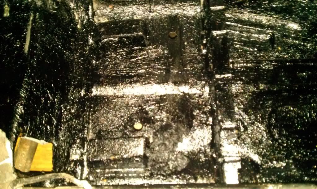
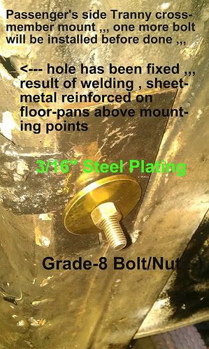
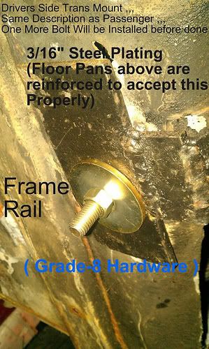
Well ... today coated passengers side floor boards ... sealed seams before hand ... tubing structure to hold trans mount is welded in and sitting close to the trans tunnel ... just in front of the seat mount.
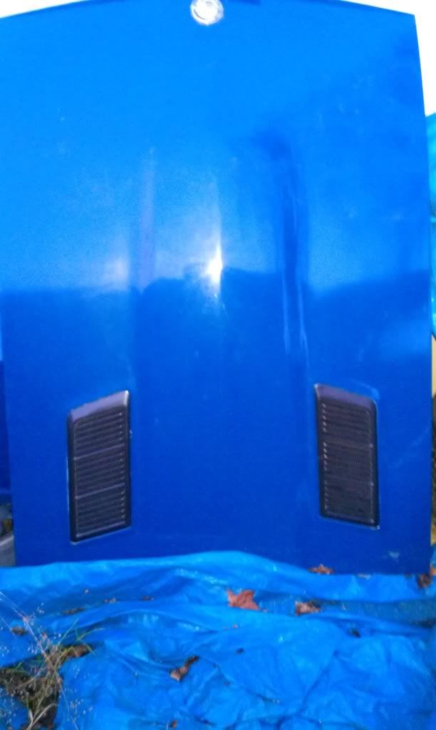
Picked up a 77 double scooped 280z hood ... this will go on later down the road
-
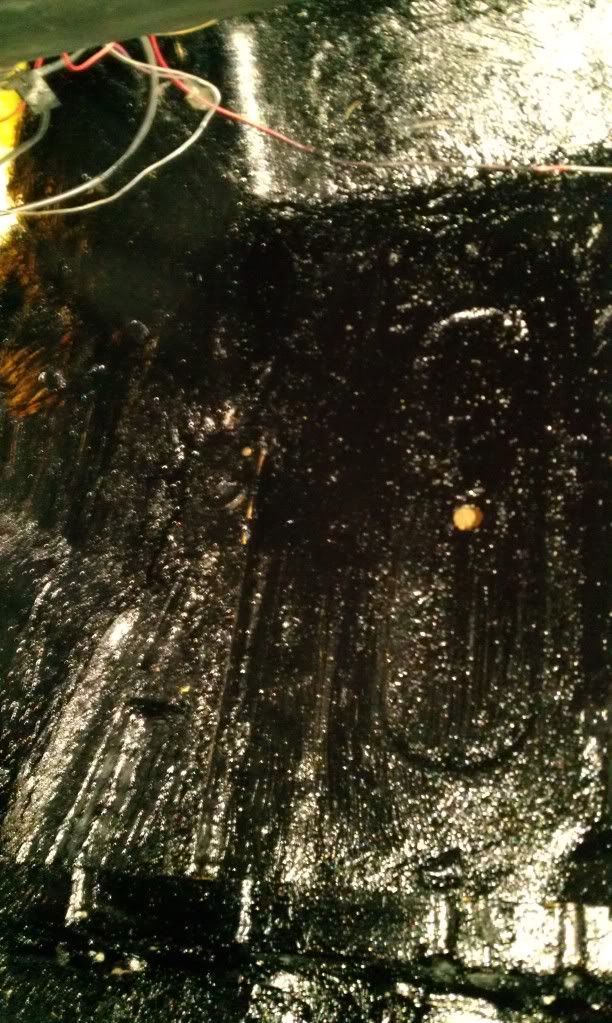
Vacuumed out mice poop and organized interior today. I did this in order to see if anyl possible patch welding is to be done beforemoving onto por-15 coating phase. I am getting ready to order some por-15 or eastwood products equilvalent soon... i am doing some more research before ordering to satisfy the system i will be using. I also need to decide if i will be extending the floor pan frame rails before coating anything in this "reasonably" priced precious chemical.
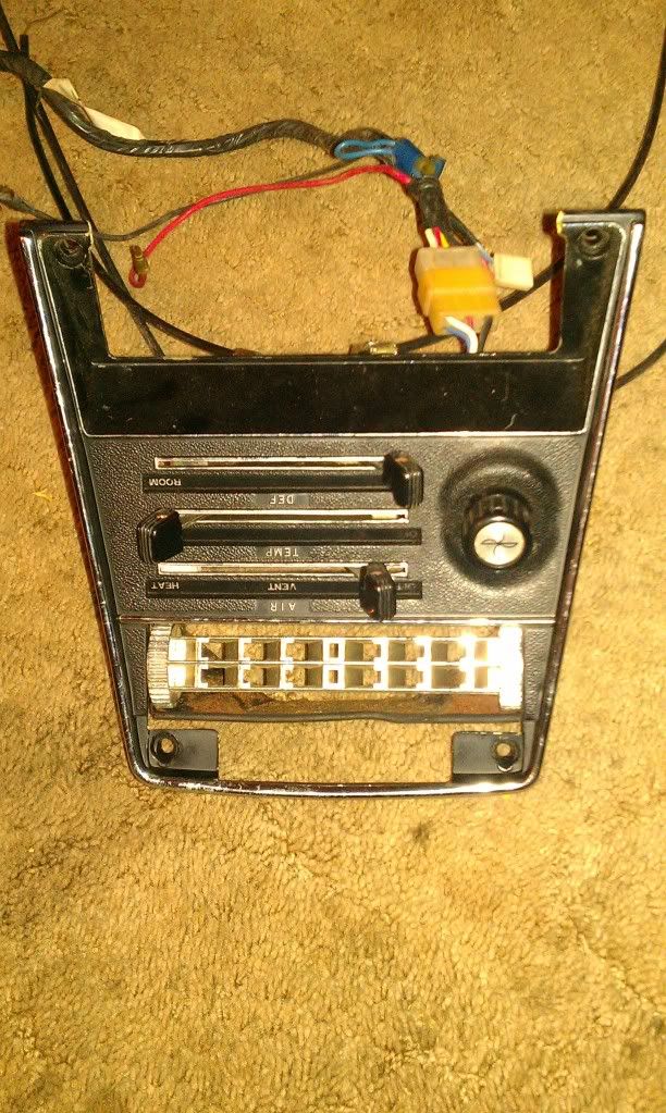
Also got a goodies in mail today ... my previous heater control panel was mutuilated
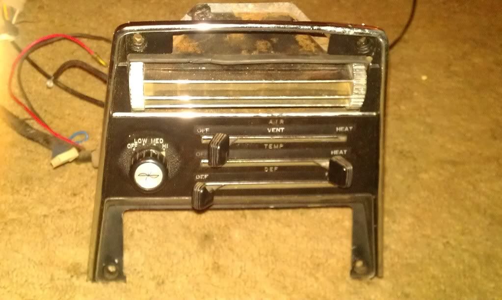
Ebay find .... 240z heater control panel with switches , cablez , and heater vent attached got it at a good price, but unfortunately the bottom bezel in which the radio sits ... is cut out .... geee thanks ebay seller for disclosing ahead of time
... got it for. 50 cents more than willing to pay though A little fixing, and it shall work. Onto the pics! !! ...
Anyone that has tried to buy these ... knows how much the price can fluctuate ... errrrr
-
Can you hear it run?
Dyno sheets and receipts/pictures provided?
Do you wish to carry off with someone else's project engine/combination at this price?
Does this fit your overall goals or current ones?
Could you retain some value in event of resale?
That's a lot of power on street lol
Questions to ask oneself in purchase
-
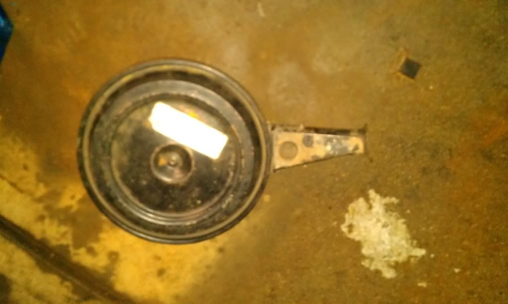
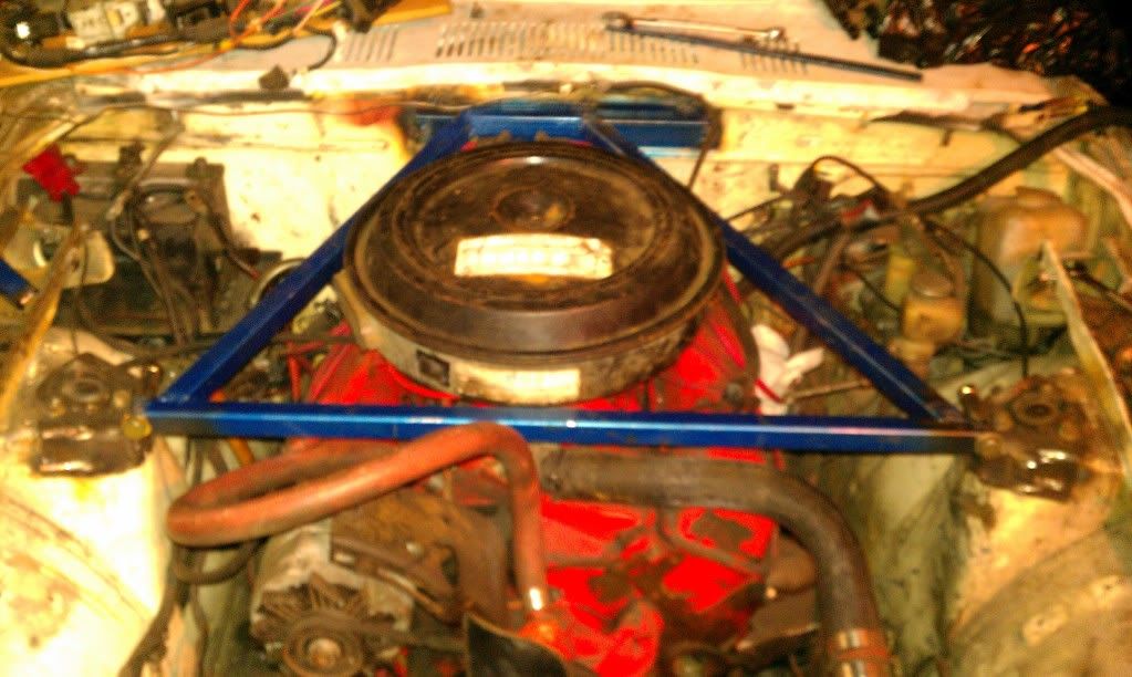
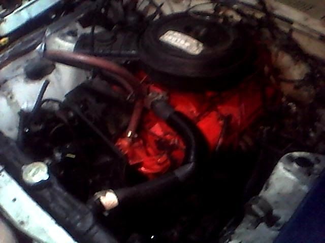
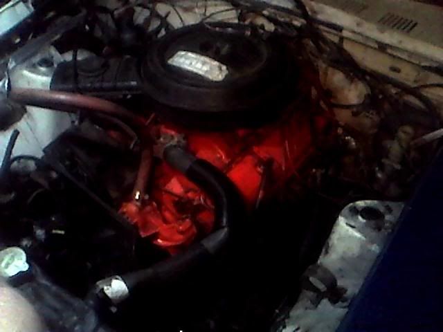
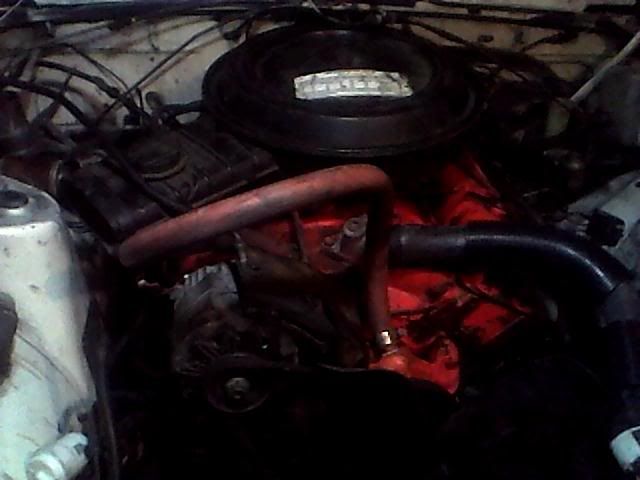
this is a stock 350sbc air cleaner ... the snout was going to be a clearance issue
So i cut it off ... heat riser valve is gone ... this air cleaner will be used for testing and until i make a custom one or low profile.
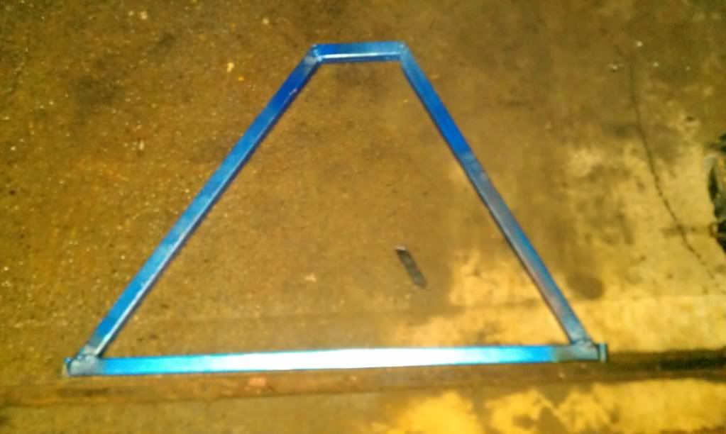
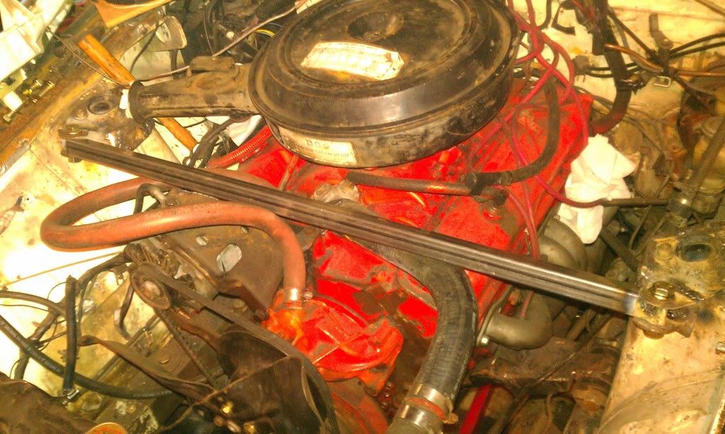
Strut tower bar ... triangulation to the firewall ... fabrication done.
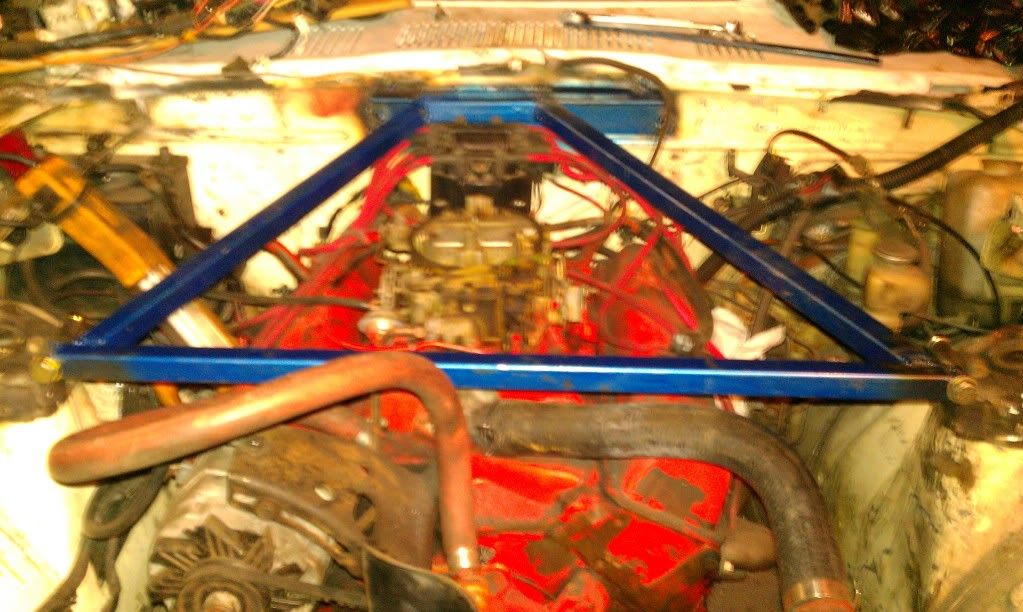
Strut bar ... triangulation to firewall bar ... installed ... distributor cap have to come off ... in order to install the strut tower bar.
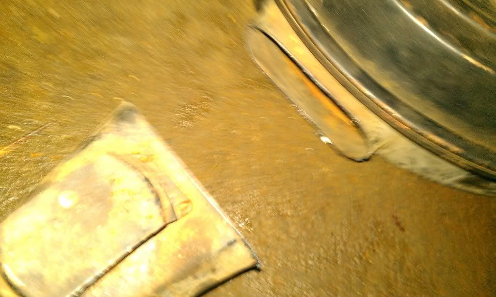
Also tack welded a long steel plate for connection points ... this will also serve az a hood latch mounting point as i had to cut off the original one ...
Air cleaner installed.
If i had ... a roll cage ... i would be using 1.25 round tubing instead of what i have used .... i would also use connection points through the firewall to bracing (obviously)
....
Painted the bars blue quickly to prevent rust over duration ... i love blue anyways lol
Also ... i will MIG weld the steel plate at firewall ... once i pull the engine again lol ( proper weld)
-
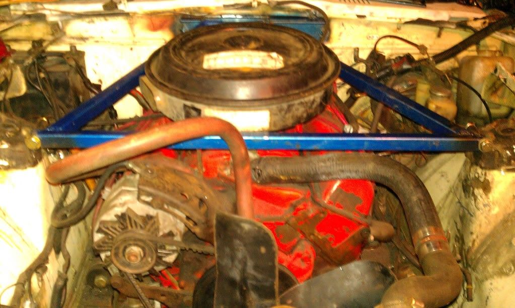
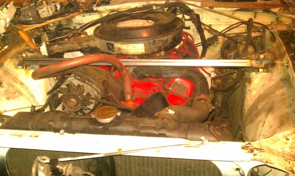
Not much of an update
I.. re-cut ... shortened ... and re-welded the strut tower bar ... threw a coat of blue paint on it for heck of it, and to slow rusting lol .... blue my favorite Color.
I know for sure i will weld two more adajacent 1" square tubing pieces ... triangulated to firewall to make just an entire 1-piece setup ..... rather than 3 seperate pieces ...
I am much happier now with this result, and moving things around a bit ...
I really need to get more done on this before spring
-
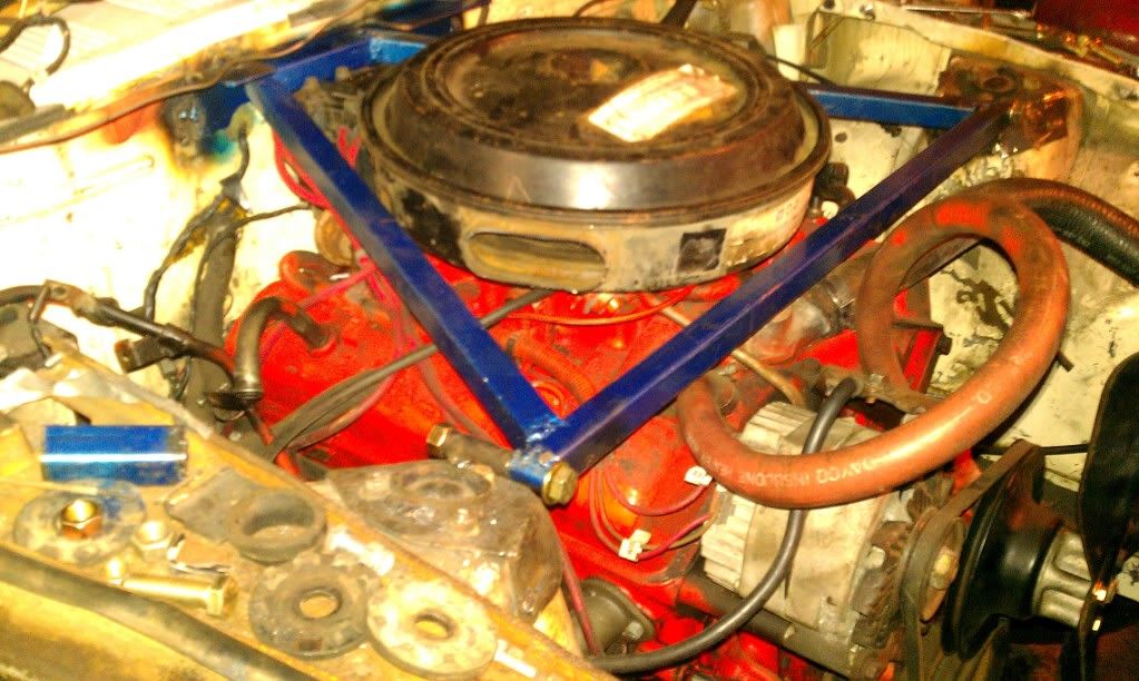
Little things ...
Cut off hood latch retaining bracket ... will be relocated ... a few inches towards drivers side ... this is to allow room for distributor/maintenance purposes ...
Deleted/took out wiper washer tubes ... they are in the way for firewall bracing purposes either way
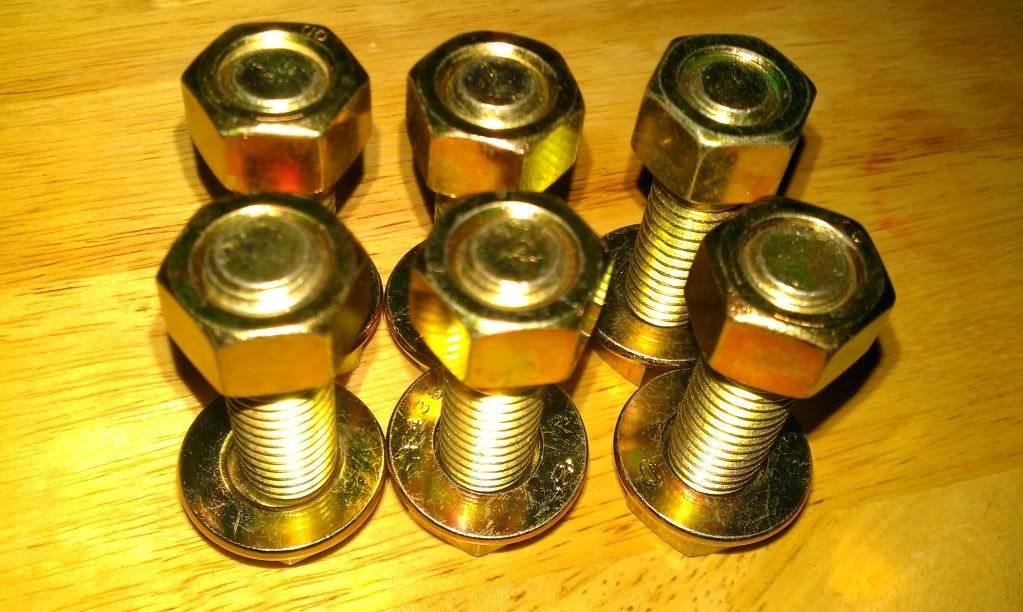
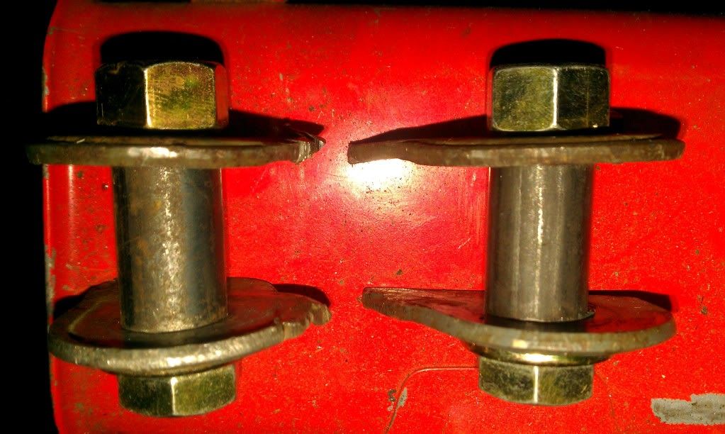
Grade-8 hardware for installing strut tower bar ... lol
1/2" I.D structural tubing pieces ... will be welded to the strut tower bar to allow removal.
Grade-8 hardware bolted to ... 1/8 plating ... in which the ears will be welded to the strut tower caps
Strut tower bar installed ... ears welded onto the strut tower caps .... bar itself is 1" diameter square tubing ...
Another angle ... looks tight ... plenty of clearance
-
In addition ... i am also thinking of moving the radiator and battery to the back. I will definetly have to research plumbing materials, flex joints, etc ...
The battery relocation seems easy peezy , but i do believe i will have to install a relay upgrade as well
I am searching
... these two points deserve their own post in my build since they are of low priority until many other things are taken care of first. -
.. forgot i had these!
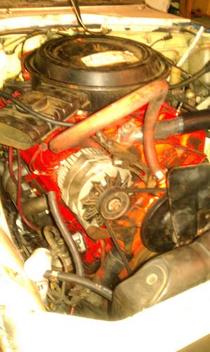
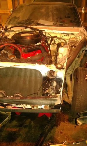
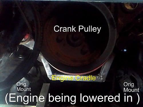
71 240z ... Gen I 350 Chevy ... ( its now 3/4" farther back since this pic) .... J I could run a smaller balancer to drop the engine another 7/8" (per JTR specs) ... but I prefer the larger factory balancer lol.... 5/8" clearancer between balancer and steering rack if wondering
... its all in my build thread in my sig. Engine is offset to passengers side as well in pictures.73 240z daily driver ... L28 engine ... factory position
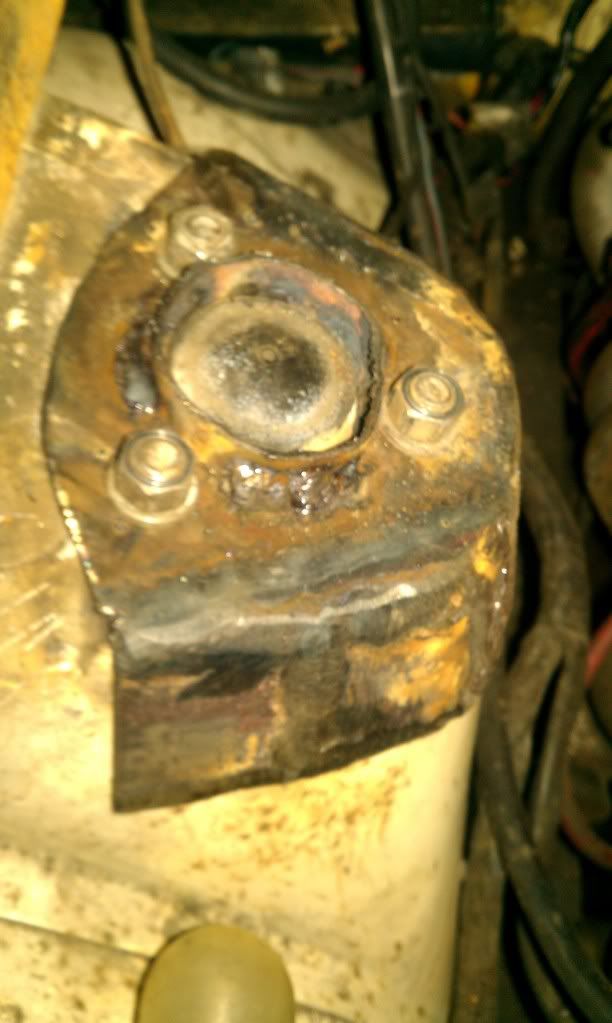
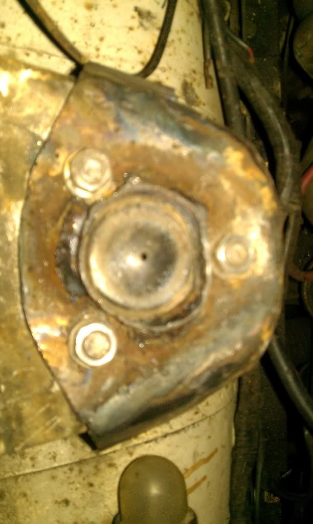
... absolutely love the l28 ... mileage .. low end torque ... zx 5spdStrut tower cap looking things ... i built these to wrap like a cone around top of strut tower ... They are then bolted down on top ... then pinch weld three connecting points at the base that allow the caps to come off (I may just MIG weld them in completely to be done with it) ... a front strut tower bar will be built... attached ... then triangulation from each strut tower cap to centerish of firewall ... via two additional pieces of tubing ...
Still need to br finished ... final fitting ... these were ARC welded and ground down mostly ... these will get body-work when the rest of the car gets to that phase
i decided to span the load of the triangulation points across the firewall attachment ... as best i can before finishing ... this is due to the idea of sharing the load,across, and in the event of s bad wreck i do not wish for this to be a harpoon lol.
Building a rear ... strut tower bar ... it will be triangulated as well ... versus just a a single connection bar clear across the top...
-
Agreed with nullbound
,,, get an earlier shifter ,, or if you cut out the tunnel just remember there are brake lines going down the passenger side on the top to the right of the shifter ! I did this same exact swap you are looking at on my 73 240z ,,, and found out exactly what nullbound said ! Swapped shifters , and problem solved !
Because you have a 71 ,,, your rear diff ,,, if it is a stock r-180 ,,, and a stock 70-71 r-180 mustache bar ,,, you will HAVE TO use your current driveline ,,, as the rear diff is "farther forward" than the rest of the s30 models ,,, this means you have a shorter drive-line currently ,,, so ,,,a 73-ish and later s30's will have longer drive-line's than your's ,,, if you convert to r-200 ,,, you will need a longer drive-line such as from the 72+ s30 series that apply ,,, you can't use a 2+2 driveshaft unless you buy it ,,, then take it down to a driveline shop and have them shorten it. So if it's a 2+2 your pulling it out of ,,, driveshaft is too long period.
In my project 71 ,,, I took out my drive-line ,,, and compared to 4 other various non 2+2 model 240-280z drive-line's I had ,,, It was indeed shorter (from the 71) ,,, If you decide to go with the 280z/zx shaft ,,, check that the mating flange will work (search) ,,, and remember those are pressed/swedged in U-joints !
Also consider getting the R-200/half-shaft's from that 280zx ,,, and grab yourself a 280z mustache bar ! Stronger-Rear-end ,,, and 3.54-3.90-4.11 !?(200sx mod I think ?) Final Drive Gear Ratios to choose from (open differential's) ,,, of course you can get an R-180 3.36 or 3.54 ,,, of course you will need the 280z or later 240z drive-line at that point
I enjoy 3.54 for highway cruising ,,, 3.90 is good for town ! ,,, poly bushings tend to resonate a lot of noise ( just a thought) for if you choose to change those out !
Use only GL-4 Gear Oil Approved fluids ( I think Napa In-House Brand , and Redline are two I know of/use ),,, not all GL-5 Fluids are "yellow metal safe" ,,, even though they specify they are ! ,,, approximately 2qts of gear oil ,,,
I believe your a member of "ratsun" as well ! haha
-
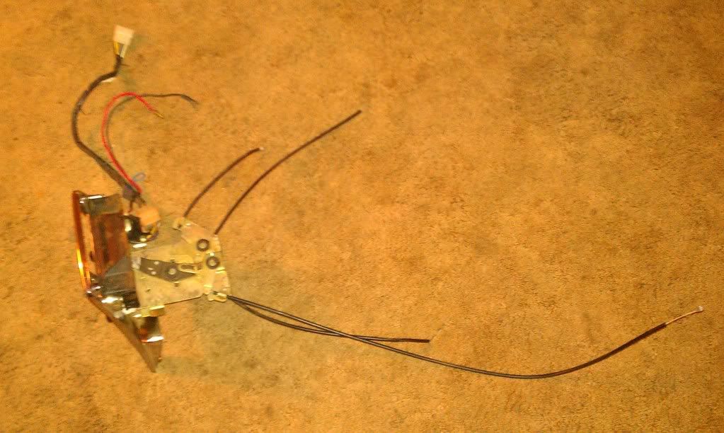
We all know ideally that a transmission should be diagnosed while driving. Well ,,, I do not have that luxury at the moment , so I will stick with what I am able to do !
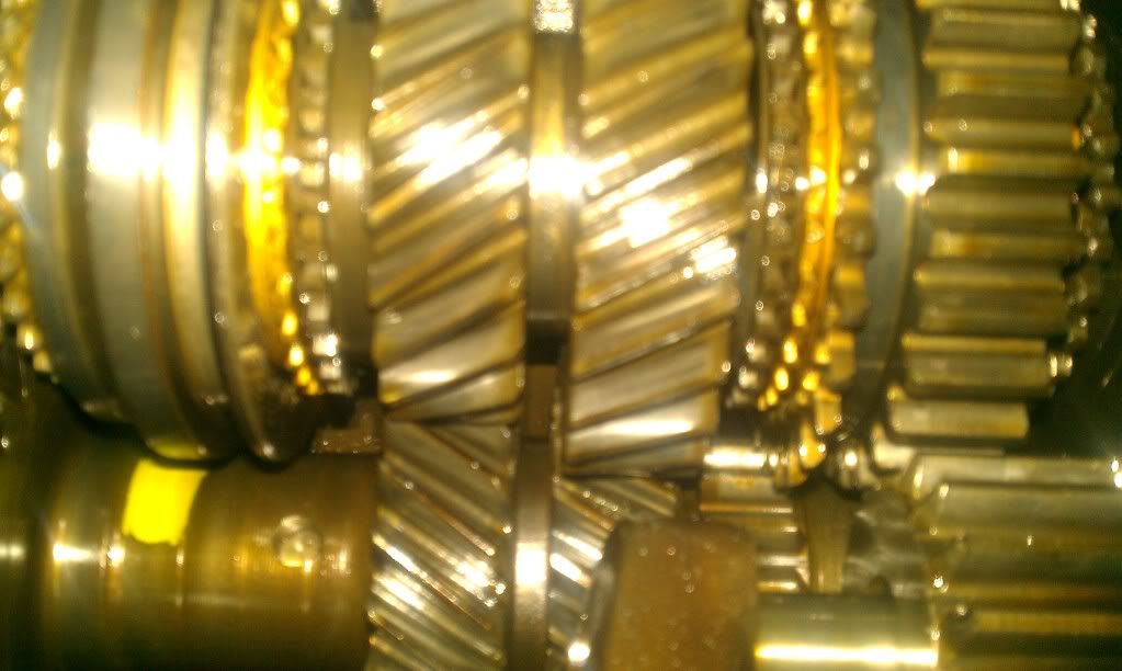
Delayed initial start up testing. I put my focus back on transmission after worrying about that funny feeling ! I proceeded to pull off the side-cover again , the synchro teeth all looked to be excellent in every gear ! I then slid the synchro hubs back and forth with my hands , and that proved to check out well ! I cannot see the dogs , or the synchro springs/hubs. So I am doing what I can to help diagnose or ease my worrying mind.
I then proceeded to check the shift forks. They looked like they were in good condition. The 3rd-4th fork has a little wear but not a lot , and that is only normal !
I picked up the side-cover that was housing the shift-forks. I then proceeded to work them , and inspected them for a bit. Next , I put the side-cover back on the transmission. I then operated it the gear selectors manually at the side-cover. Strangely it felt a little different ! I pulled off the side-cover. I took the spring at the bottom in the picture , and cupped it a bit tighter. I put the side-cover back on the transmission. At that point it felt smoother! Transmission guy around the corner said these can become weak ... and mimic the conditions of a worn synchronous block ring ...
I will be ordering one soon , and installing it ! Transmission all back together for now ! I do not know if this is the issue , but gotta start somewhere ! The gentleman I bought this transmission from said "It was rebuilt 1 year ago". As we all know ,,, it seems little elf's are working round the clock to rebuild every-transmission that is for sale (rolleyes). To his credit , I have not had a chance to test this transmission , and the synchro's/gears look to be promising shape !
I will be thoroughly inspecting the synchro dogs , hubs , splines , springs , etc once the transmission is to be rebuilt. I know the feeling is not in the linkage or original shifter. I know that won't be helping anything at any-rate lol ! Another excuse to hunt for my Hurst !.
I am still chugging away on this project ! That's it for this moment (January 3rd 1:06 PST) ,,, Happy New Year ! I will try to update again soon
-
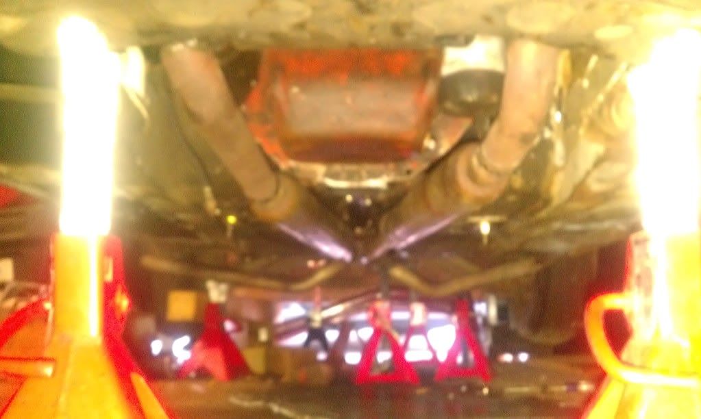
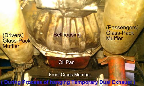
I thought I had posted a picture of my re-used , and recycled exhaust lol ! here it is !!! ( rear exit pipes will be cut/re-welded so they don't scrape) This is really more of a test exhaust system , and I probably will keep the glass-packs if I can.
The car is on four jack stands. The rest of the jack-stands were used to hold the exhaust in place , so I would be able to tack weld the exhaust. I then pulled each side one at a time , and finished welding them on the bench. Finally I re-installed them.
NOTE : ---> I eliminated the "bends" towards the center back are of the exhaust since this picture. Obviously these would have scraped ! lol. These bends were how the exhaust shop ran the exhaust on the donor truck.
-
Patched together dual exhaust tonight , and will use to test ! Then once bugs figured out as well as car licensed I will drive down to exhaust shop . I will then play quote battle with the exhaust shop ! lol. Ultimately I will have them run a nice pretty new 2.25-2.5" Dual exhaust ,,,
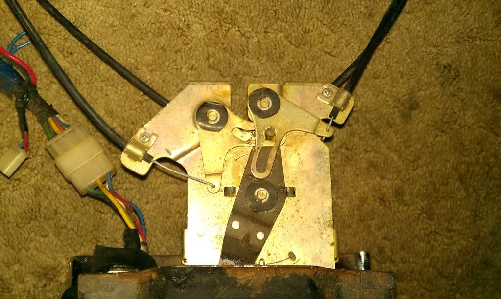
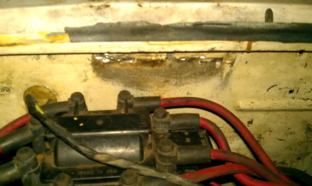
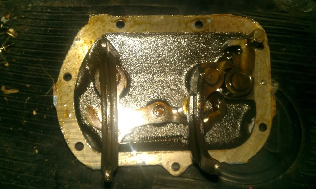
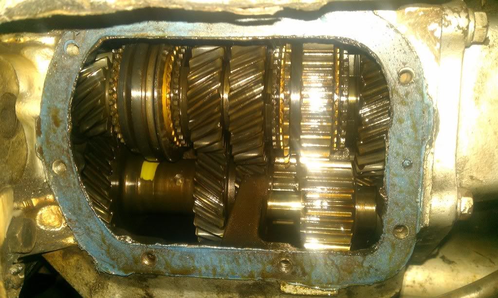
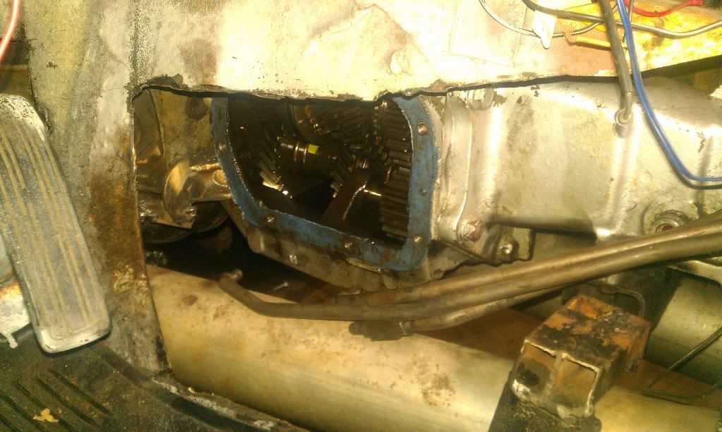
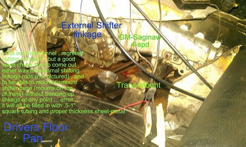
. Until then a used dual 2" exhaust shall do !! Also , I Took off the transmission side-cover to re-seal it. This is the external linkage to the shift-forks located in this cover (picture).
Linkage Rods are disconnected in this picture. They are held on by washers on the back-side , and cotter-key type pins ? ( I need to buy the correct ones as non-correct ones were provided with my used transmission purchase ! )
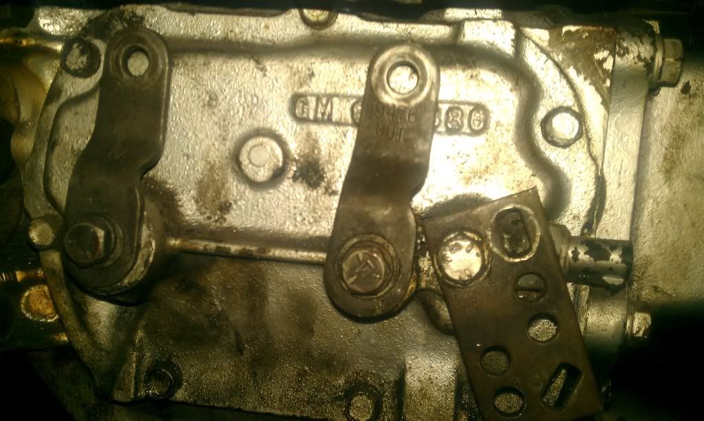
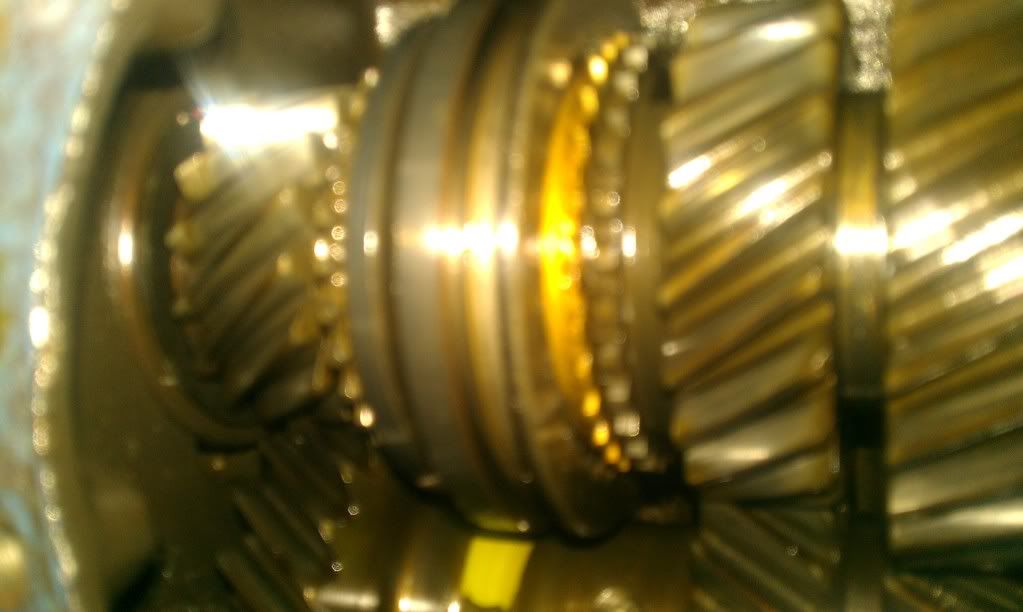
Pulled off the cover , and you can see gears inside ! They look to be in good condition. Of course it needs GL-4 Gear Fluid as well , because of the Gold Metal ( Synchro's )
This is a picture of the inside of the shifter/transmission cover , and you can see (2) Shift forks poking out . Shift fork on the right is 1st/2nd gear shift fork. Shift Fork on the left is 3rd/4th gear shift fork . Reverse has it's own system ! lol ( a little paw selector )
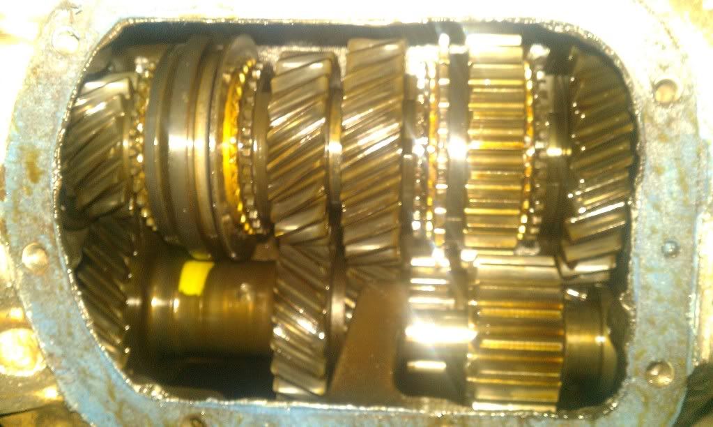
(Top Gears in Picture ) ,,, From Far Left ---> (Top Gears) ,,, 4th ,,, 3rd ,,,, 2nd ,,,, (Reverse ,,, the one with straight cut gears ) ,,,, 1st
(Bottom Gears in Picture ) ,,, Cluster Shaft Gears ,,, non-removable I believe ?
In this picture Showing access cover is on the drivers side. I will leave it open for now , and reseal it later. I want to take a closer look at 2nd Gear Synchro/hub/fork. I stated earlier in this portion , that 2nd feels a touch funny shifting. I am being really really picky. Synchro look really good ! I will be noting this for sure , and test/work out bugs on whole V8 conversion. Then rebuild/repair this transmission myself or have this done by a transmission shop if reasonably effective all around. Initially I was quoted around the $400 figure to have this done.
-
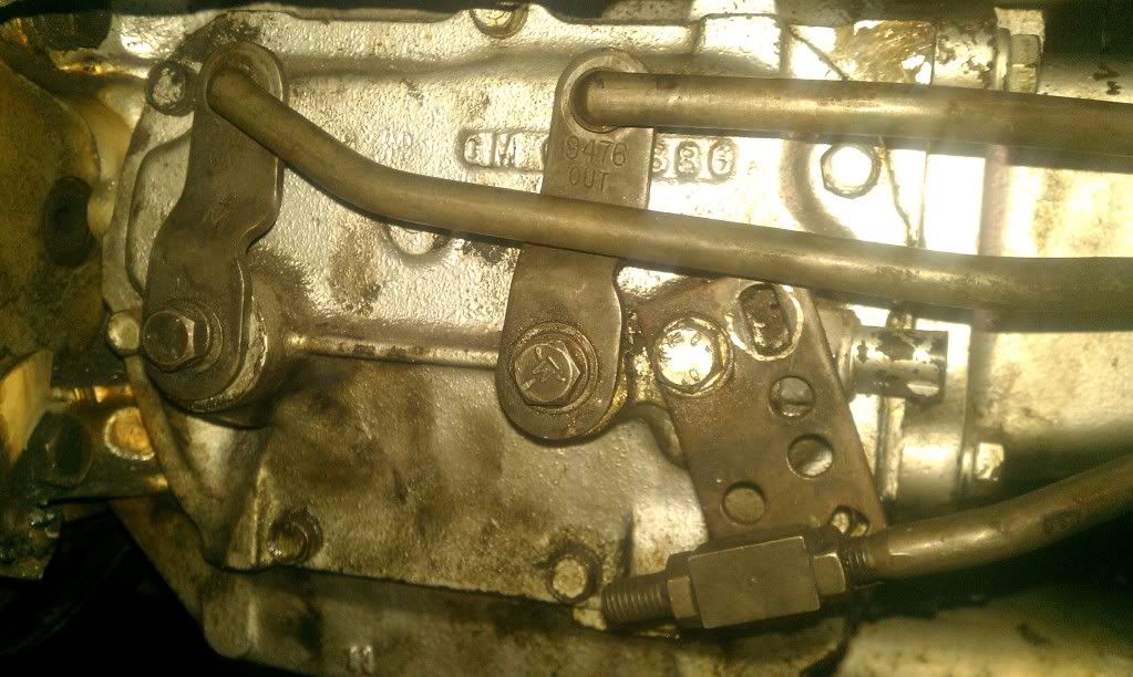
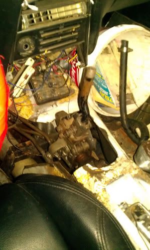
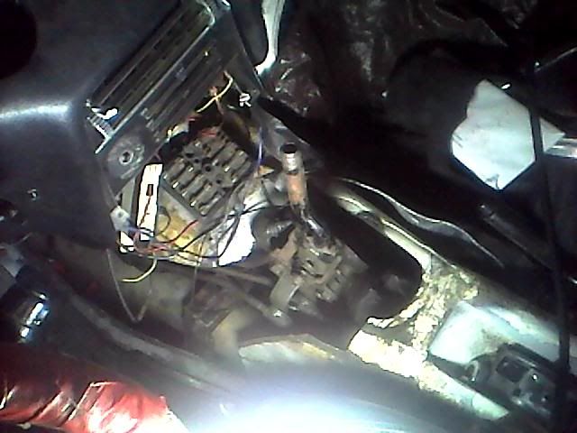
I Installed the GM "Chevelle !?(not entirely sure now ,,,all I know is it works ! haha ) 4-speed Saginaw Shifter. A bit of clearance in front of the bracket , and shifts freely without touching anything ! I really need to take it apart and clean/re-grease the mechanism itself.
The assembly bolts onto the passenger's side of the tail-shaft ,and the working mechanism itself is off-set towards the driver ! Cool ! Of course I really wish I just had a "Hurst" Shifting assembling instead. If you have ever felt/drove one then you know what I'm saying !!
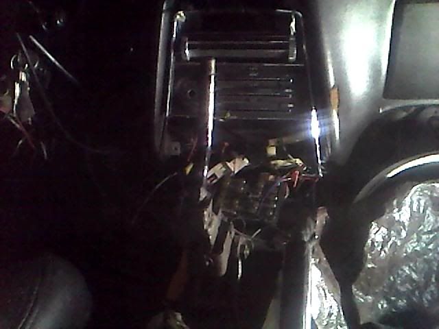
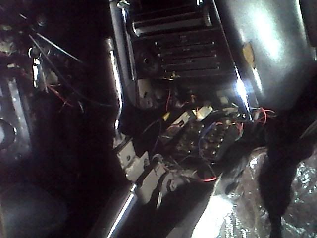
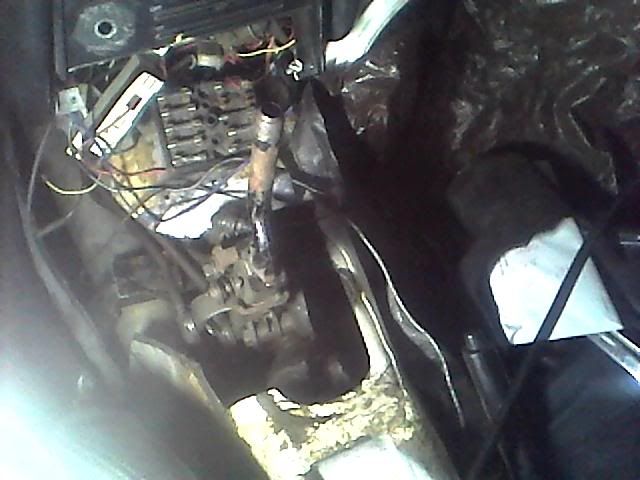
(Laptop cam) Drivers side floor ,and you can see the linkage hookup. It also appears that the speedometer cable outlet on the transmission will be a challenge as well
. It points straight through where I planned to put the "reinforced access cover" ( I might need a 90-degree adapter of some sort if they make them. I will be researching this !Shifter linkage rods are in , and engaged at the transmission! ( The shift forks are located in the cover obviously ,,, 1st/2nd share one ,,, 3rd/4th share one ,,, reverse has it's own fork ! For a "Cast Iron Case" Transmission , it's fairly light to me
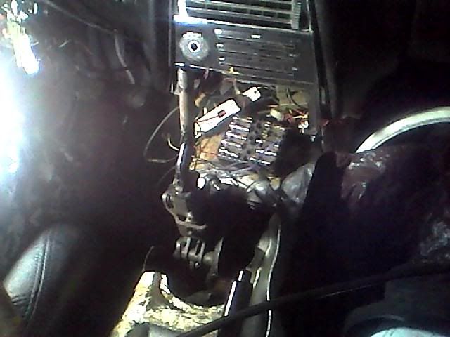
Picture looking from drivers side(column doesn't have cover on it ). Shifter height actually ideal with the seat that is currently in there ! Critical wiring seems to be "ok" , and accessory stuff ( heater , radio ) is kind poop at the moment
.You can also see my "Dual Glass-Pack" Mufflers below the trans ,,, love it ! haha
Shifter height I am getting use to ! It's nice once you sit in it and feel it ! It is engaged in first gear in the picture.
-
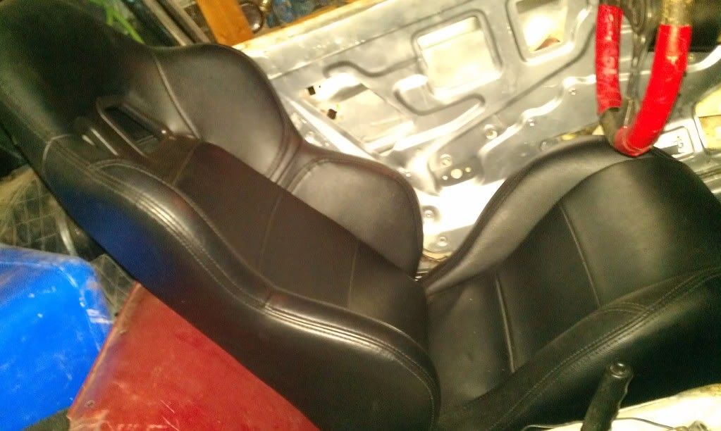
Test fitting some seats I got from a buddy for cheap ! He had purchased them from "Summit Racing".
A bit tight , but they will do !
-
( Descriptions in this post in progress .... )
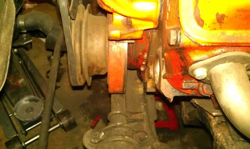
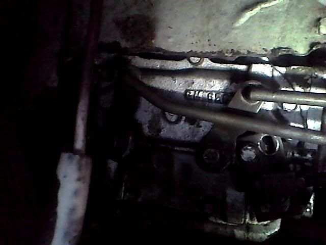
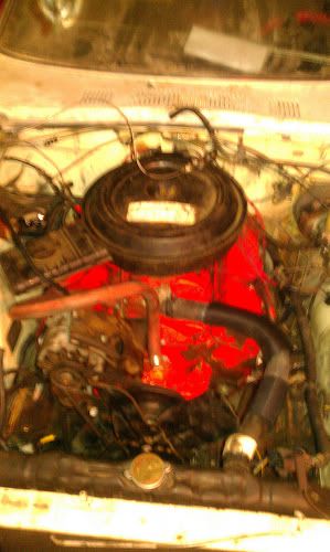
After setting in the engine , this is the "Played" with result of clearance between the steering rack and engine Harmonic Balancer. It seemed 5/8" clearance seems plenty , but I felt safer it being just a touch higher assuming my motor mount rips or motor rock is an issue
. I originally had this clearance at about 1/4"-3/8". I am aware of smaller 6.25" balancer per JTR , but I do not have the money at the time. I then proceeded with the 8" balancer !Notice motor "Cradle" clears the steering arm ,,,
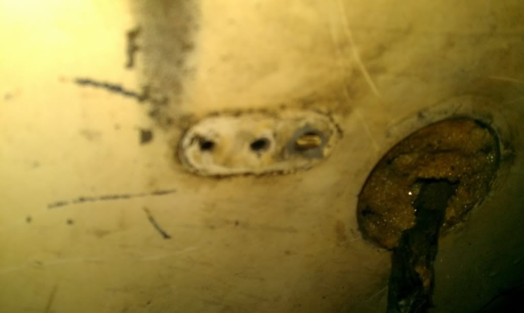
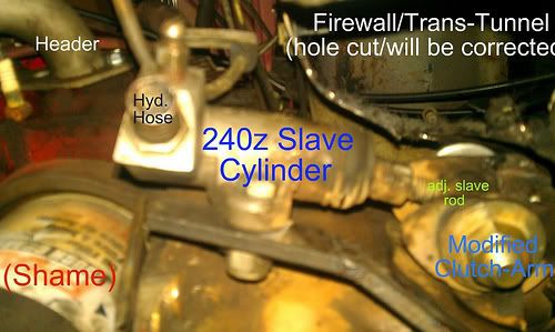
. engine crankshaft center-line is "off-set" to passengers side obviously.This is obviously a pic from underneath , and on the drivers side of the vehicle. The hole you see above was my noob to engine swap mistakes (manual trans). I had originally "clearance" the clutch arm to be able toi fit inside a pocket of the firewall area. Somehow in my drunken calculation , I had forget about the Gas Pedal being RIGHT THERE
. I proceeded to shorten the clutch arm as short as I could stand working with. I then modified it to what you see now. If you look at the trans tunnel currently ( in this picture ) you will see I still have to "massage" the trans-tunnel lightly . No worries boy's and girls , and this hole will be MIG welded back up solid with reinforcement !.The slave cylinder is now mounted on the "drivers side" as opposed to the "passengers side" of the transmission ( from factory ). I now must move or "re-bend" the factory clutch hydraulic line , to be able to use the original line. I have not achieved this yet , and am afraid to try at the moment lol. Which of course brings me to making up a "new" hydraulic line (correct way) -to-hydraulic soft line which connects to the slave cylinder.
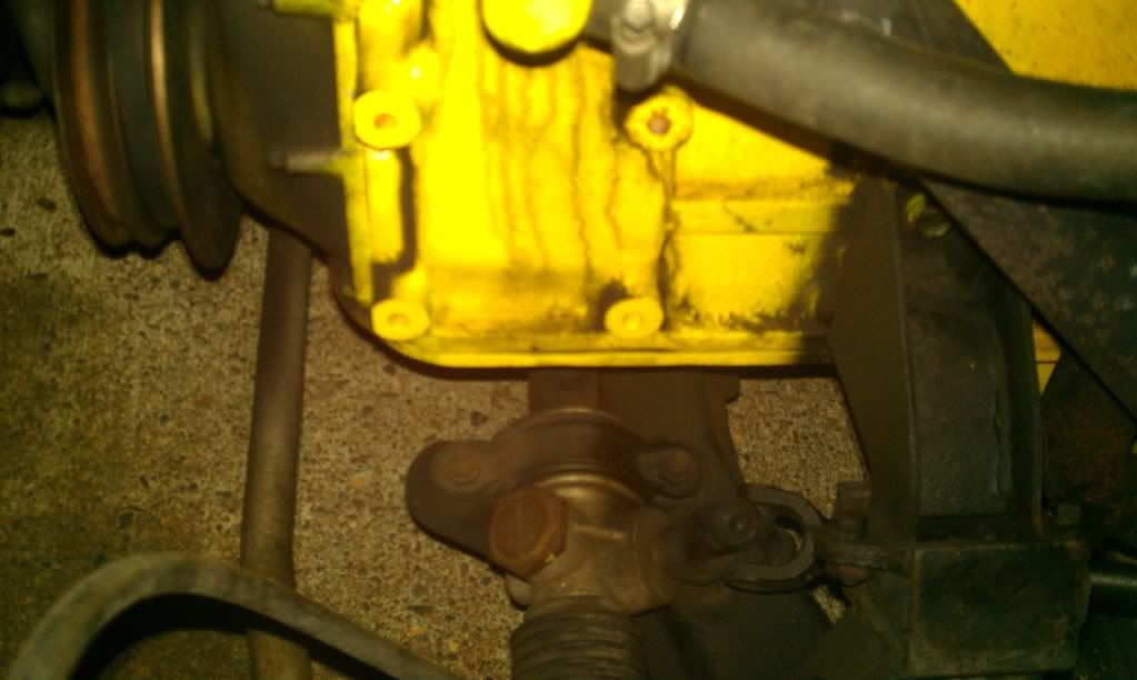
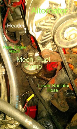
This picture shows the mechanical fuel pump is hovering above the passenger's side original factory motor mount ! As mentioned before clearance was marginal , but still "ok? . Since this picture , I took a grinder cut-off wheel to give the fuel pump a little more room ! ( What I really should have just done was weld locators into the cross-member(jig) , and cut welds off both factory Hard Plate mounts. Then take them off ,,and keep them for later if I ever wanted an L-series engine back in the car ! )
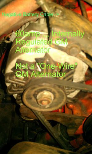
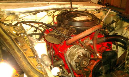
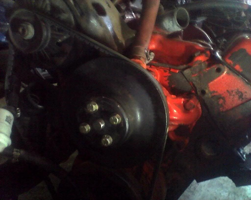
This picture shows an ,,, Internally regulated GM 65amp ? Alternator ,and the Negative battery cable grounding point was on the alternator bracket ( Factory GM Point ). A V-Belt shown obviously from age as well as era !
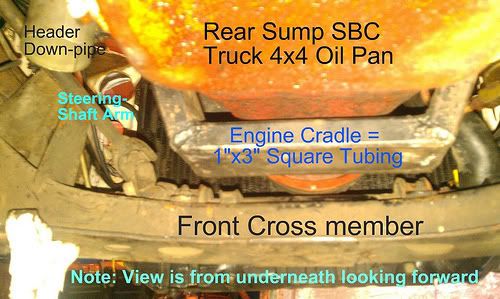
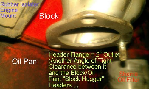
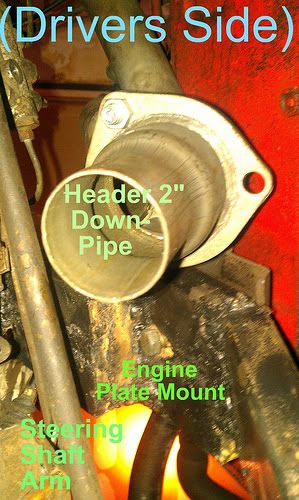
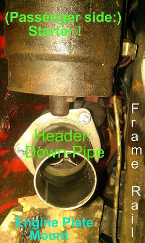
Pictured is my engine cradle wrapping around the oil pan , and it clears about 1/2"-9/16" from the pan itself. Could possibly be just a touch more. The cradle fits very nicely ! The connecting "U-Shape" piece is made of 1"x3" Square tubing ( thicker than usual ,,but can't remember how thick at this moment in time ) Header Down-pipes shown in the picture. Steering linkage arm is shown as well.
Rear sump oil pan is again from a 1975 Chevy 4x4 350 (4-bolt main)
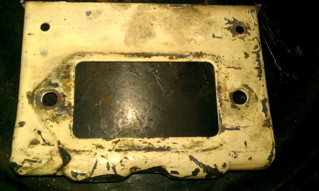
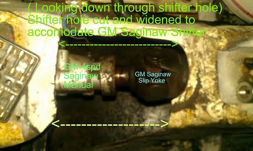
In this picture I Regret having to cut such a large hole , and it was painful to do so. I had to be able to get at the external linkage somehow with installation , and so on. It doesn't make sense what I did in this picture , that is until you have to actually WORK with the parts I am using
. I choose this path , and know one to blame but my budget as well as myself ! hahaThis picture is looking straight down through the shifter hole , and you can actually see that the crankshaft center-line is offset to the passenger's side (cool !) Also this is in alignment(as close as I could get realistically get it ) with the differential !
Also is all of the "widening" and "cutting" on the shifter hole/trans tunnel. hat I had to pursue and execute ,,, in order to achieve a working system with my new found transmission. I'm not too happy about this , but it is my first "official" engine conversion. Live , learn , and a hater's gonna hate !
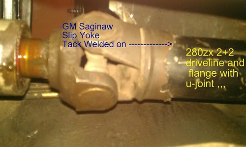
This drive-shaft is for mock up only. Allows me to see transmission height , and clearances around the brake Lines as parking brake cable. Of course sheet-metal was a concern in itself . The Front of the drive-shaft looks funny , because it was a slip yoke that was torched off by previous owner of the transmission. Ultimately just the slip yoke will be knocked out , and attached to a longer gm drive-shaft. I then will attach my R200 adapter flange to this drive-shaft longer GM drive-shaft. I measured for a new drive-shaft already at this point. Finally when I am ready , I will take the GM drive-shaft to be shortened/balanced !
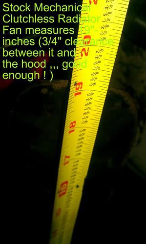
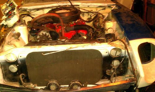
This was quite interesting ! I had a FULL SIZED 19" mechanical "clutch-less" type radiator fan Once installed it only had 3/4" clearance (to the hood) , but clearance from my top radiator hose was of no concern ! I can opt to buy an 19" , 18" , 17" , and 15" inch diameter non-flex steel fan later on. I also have an electric "Push" type fan that may be large enough for this conversion. I will stick to this 19" Mechanical Fan while working out the bugs/testing phase ! I will also test my electrical fan set-up , and compare the two for my needs !
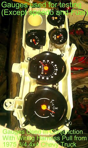
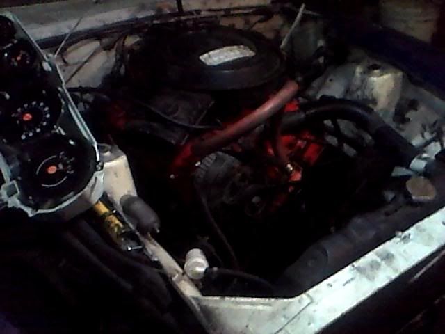
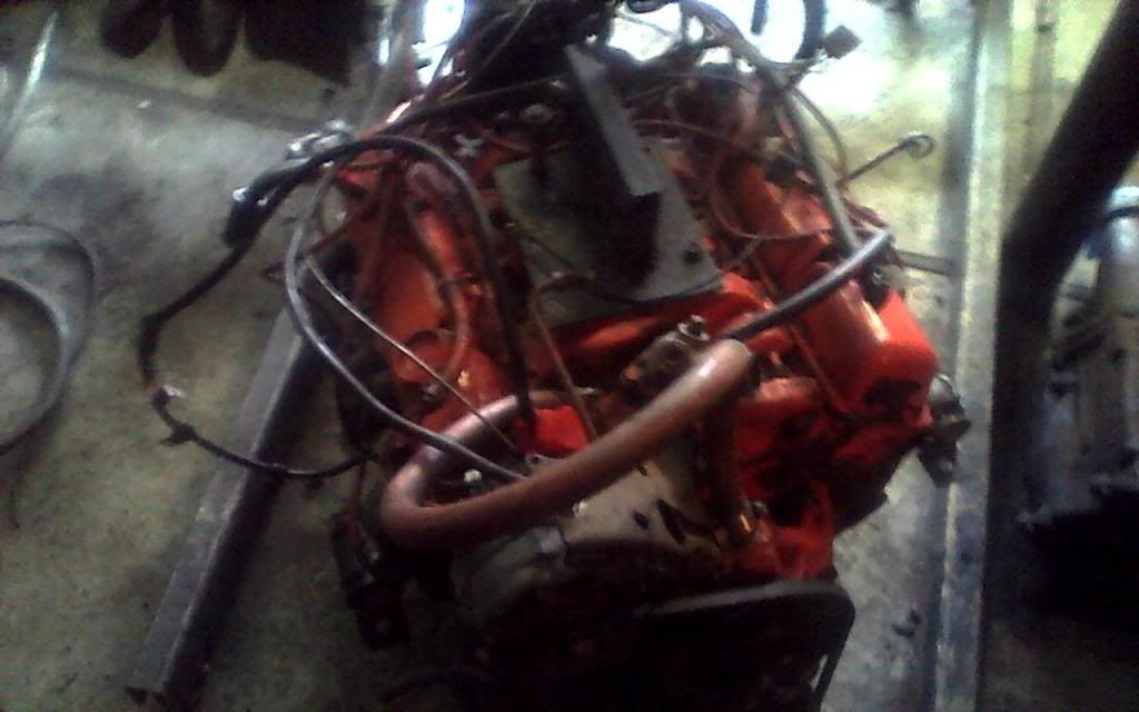
This is the gauge cluster pack from the donor 1975 Chevy Truck.The entire Gauge Pack , has a thin strip copper circuit printed film board. This copper film strip in all share a common ground , and this is how the bulbs are powered ! (cool) ,,, I use the mechanical "Oil Pressure" gauge, the "Volt" gauge ,,and "Temperature" Gauge only for this obviously lol ! You cannot separate these off the cluster without damaging them , but why would you want to separate them ?
This same set of gauges , I also use on my "Engine Testing" stand. The one you saw earlier on in this project thread ! cool huh ? ( if you scroll back up to the first post you will see them sitting below the engine ! )
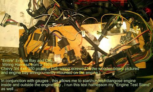
All cab and engine bay wiring from the donor 1975 Chevy 4x4 pickup. My method of securing the wiring to the board was makeshift. I grabbed some 5/8" heater hose , cut it into 2 inch or so chunks , and slit them length wise. I then proceeded to tucked the wiring inside each mounting point ,and I grabbed some sheet rock screws. Next I used a 3/8" cordless drill , screwed through the edge of the rubber. Naturally the rubber would "curl" back up to it's circular position. This would "trap" the wiring very snugly for a makeshift board.
These are glass-packs from the donor 1975 Chevy truck. Same one as the motor came from ! This will work for testing/working out bugs on car ,and maybe even a little driving. Glass packs are VERY long for this car , and hard to fit ! lol. I am glad I recessed my transmission mounts enough to tuck them in a bit more and without burning anything or clearance issues ( hopefully on the burning part lol ). I used Jack-Stands to hold/position in order to "complete" this recycled exhaust. It helped me accommodate (cut) the proper angles without too much of a fuss ! The exhaust pipe is in much better condition than appears , and is of thicker gauge.
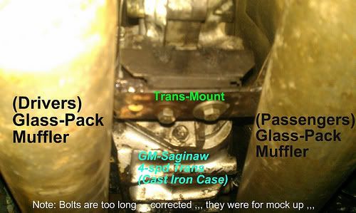
A further back angle pic of the last ,,, The transmission-mount plate on the cross-member ,,, that the rubber transmission mount bolts to ,,, was actually made from the "flat" part of the r-180 mustache bar that did not get used. I cannibalized it for the R-180 loop ends on the engine mounts ! Recycle and re-use !
. The whole mustache bar was used in both the engine and transmission mounts ! heheheI really need to grind down these welds ,,, and re-weld them all pretty like ,,, haha
. I will proceed to do that AFTER I verify/run/test/drive car. For now they just need to hold the transmission in until I get all the bugs worked out ( assuming always there will be some bugs! ) . This will happen when the motor comes out again for paint , mods , or repairs ! ( we all know it happens often , especially during these things ! lol )I really need to grind down these welds ,bevel , and re-weld.
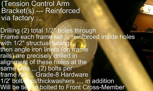
Picture says it all ! The bolt and nut you see is Grade-8 hardware. It is a 1/2" hole drilled through the "Tension Control Bracket" (TCA arm bracket) towards there rear of the engine frame rails,This is the rear mounting point for the angle iron. Earlier I lined the frame rail tops with.
( I may change out pics as this one is a touch annoying ,, with all my writing ,,, )
Driver's side from underneath , showing drivers side motor mount plate connected to the cradle. The mustache bar loop connection , and steering arm were actually an issue my first time around tack welding them in. I proceeded "Angle" the mount up in order to clear the steering arm. Success ! The steering are looks as though it is no where near the steer shaft. But , if I dropped the motor much further down ,,, I would have to be very careful with those specific clearance's on this drivers side motor mount.
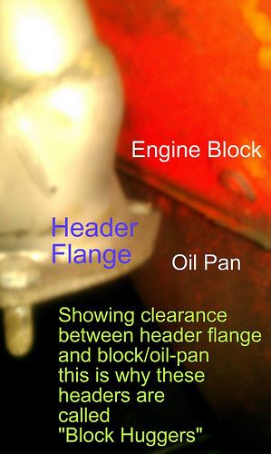
Looking at the block hugger header clearances. I will have to build a sheet-metal shield , and possibly use "header wrap" etc. I am glad I am able to "reach" , and change the starter In the car with this conversion ,,, lol
-
Drive-train In !!!
( some pics with my phone and some with my laptop ,,, apologies in advance for variations )All in and Mounted !!!
Tell me this is not ,,, Cool Looking !!!
Gauges you see on the left in this picture ,,, work when I hook up my "test harness" from the 1975 Chevy Pickup . I am very happy I took the time to pull all the wiring from that donor pickup !
-
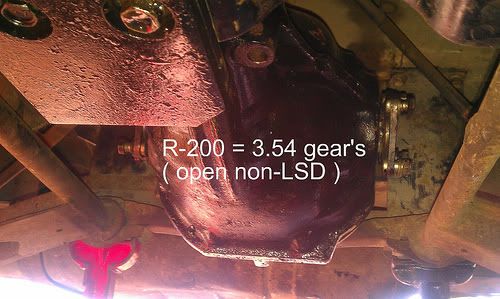
Getting Ready To Drop in Engine ! At this point , I realized I still needed to change out the Differential from a R-180 to an R-200 (3.54). So I took the R-200 Mustache Bar I had laying around , and drilled out the old rubber bushings. I then cleaned the loops/hoops with a wire wheel on a drill. Next , I installed the upper poly bushings with lube (correct lube) . I then gave differential a quick blast of black paint , and installed the mustache bar on the Differential.
I then put it on a jack with the cross-member attached to the differential , and jacked it up in position. I proceeded to bolt the cross-member in , and then lightly pushed in bottom R-200 Mustache bar bushings. Next , tightening down the bolts sucked the bushings up ,and the it all fit nicely ! here's a pic of the differential ( no current pics of Mustache bar ,,, I will have to get some )
This is the part where I do the "Engine Hoist" dance lol ( swing Engine Hoist 180 degrees around the engine that is sitting on blocks/ jack stands )
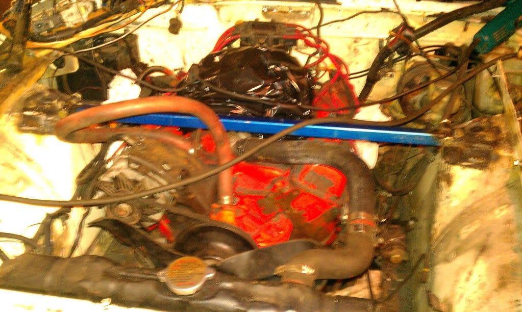
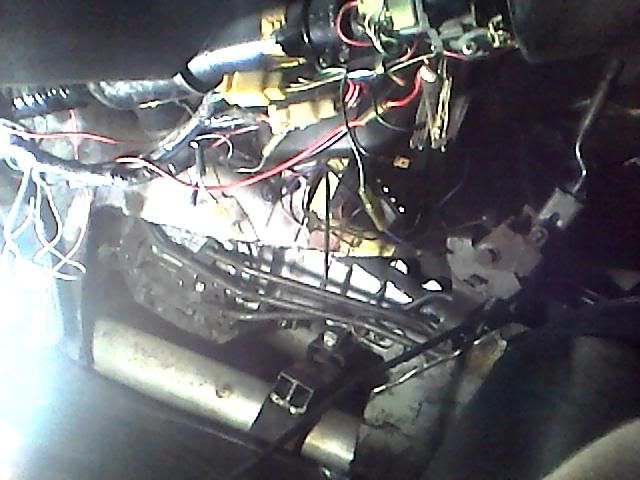
In this picture I then flopped over the battery cables/wires , and made sure nothing will catch when dropping in the engine ! Picture is getting ready to position engine/trans to be able to be craned in ,,,
I really can't remember why I needed this much angle ?,,, haha !
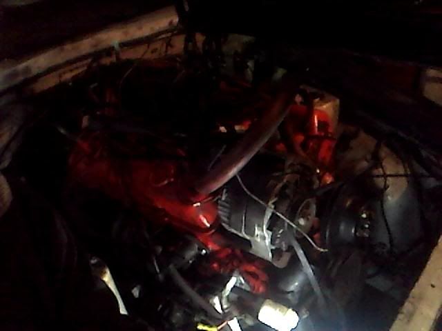
Hard to see this one , and it is from the passenger side ,,, lowering engine in ,,, apologies for the darkness !

 ... got it for. 50 cents more than willing to pay though

 . It points straight through where I planned to put the "reinforced access cover" ( I might need a 90-degree adapter of some sort if they make them. I will be researching this !
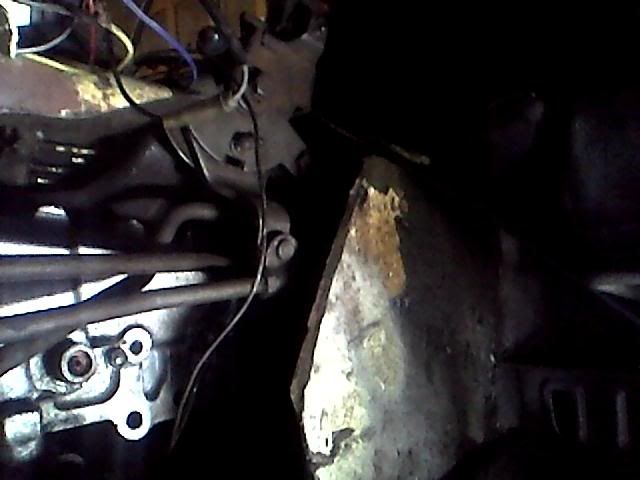
 . I originally had this clearance at about 1/4"-3/8". I am aware of smaller 6.25" balancer per JTR , but I do not have the money at the time. I then proceeded with the 8" balancer !
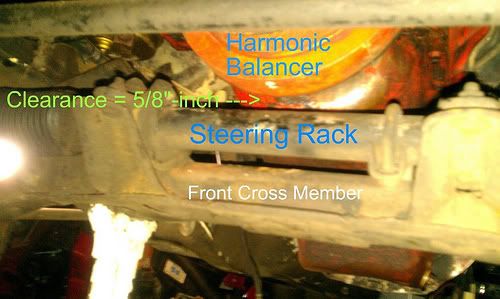


WTB 240z Passenger Fender
in Parts Wanted
Posted
I believe i have one pm me as i want to look it over before giving price
Portland,Or metro area