

Chris Duncan
-
Posts
163 -
Joined
-
Last visited
-
Days Won
1
Content Type
Profiles
Forums
Blogs
Events
Gallery
Downloads
Store
Posts posted by Chris Duncan
-
-
Thanks, I'll try and see what happens.
Another thing you should consider is don't re-use your old studs, get some new ones. These studs regularly break, especially the rear one.
Napa sells a stud kit of 10 count 8mm studs with nuts. Part number NOE-600-2604
Not 100% positive but think the carb manifold does not use the larger 10mm thread holes in the head, that's only for the FI manifolds.
-
This comment here set my brain in motion. Sorry if I rain on your parade here, not my intent, but I really think you've got some problems with your testing.
Seems to me that your test rig reinforces the front strut towers from twisting, and it actually might do that job quite effectively. You've got the lower control arm stand in and the strut stand in welded together and bolted to what looks like a 2x6 presumably pretty heavy walled piece of steel. That assembly is fighting the torsion that you're putting in, and I would think that it is adding a lot of stiffness compared to stock. Add to this the idea that you put the torque into the lower frame rail in the back, not the strut tower there, and your test is more of the lower frame rails and rocker's ability to resist torsion when aided by the front reinforcement.
I dunno. Maybe I'm wrong, but the more I think about this the more I think you need the actual suspension members in there and you need to put loads into them, not the frame rails themselves. You're putting torque into the chassis, but you've also reinforced it at the same time. My suspicion is that you'd end up with MUCH lower numbers with the front end tested at the hubs.
Just looking at the "Think Fast" book again, he describes mounting the chassis via the hubs, and says: "The wheel mount blades should be very stiff, but only in the vertical direction. They should be flexible in all other directions so that the fixture does not artificially stiffen the car." Your front and rear setups look rigid in all but beam.
I think in order to do this test and get really accurate results the suspension will have to be all metal to metal bushings. Your thread had me considering doing something similar, but my plan was to do it through the hubs. I have all monoballs and heims joints except stock front ball joints. I think even they would have to go in order to make this sort of testing accurate.
Looking at what you're saying I think you are somewhat correct.
The front stand-ins are solildly bolted to the 2" x 4" x 1/8" testing beam, so that aspect is not going to simulate the actual parts. However the way the strut and lower arm stand-ins are attached to each other at the lower outer ball joint position is set up to flex, so that is closer to the actual set-up. So I think the torsional rigidity test is somewhat accurate and the front strut tower brace test is less accurate. So to improve this set up one of the testing beam attachement points would have to have a sliding feature so that the lower ball joint positions are not rigidly attached to each other.
In addition to increase accuracy the rear could be set up with similar strut and lower arm stand-ins. I had origially started to do this but in the interest of time decided the accuracy for the intended purpose would be enough with the direct bolt up to the chassis.
Chumpcar penalizes metal to metal bushings and to be 100% accurate you would also need solid strut top mounts. Going in I didn't think this would have full accuracy, what I tried to emphasize was uniform repeatability. Trying to apply the same test over and over to observe the results of different changes. And I think that was achieved enough for the intended purpose. The seam welding does not have enough return for the time and expense it takes and the roll cage does add a significant amount of rigidity especially with the added cage to body gussets. I believe it was also indicated by someone's reply that the overall rigidity number was close to what others have seen in the past.
One thing that was discovered that I haven't seen anyone else do is the method to load the beam, this makes quick repeatable testing much easier. Of course that doesn't mean it's never been done, just that nobody has put it out there.
-
Pretty sure it becomes obvious once you set the manifolds against the head.
-
Pics of the cage?
Anything forward of the firewall? I am guessing of course, but I assume a lot of the torsional movement is happening towards the front of the cabin and after the firewall.
It's a very standard 6 point cage, X's in the doors, 45's to the rear strut tops. Diagonal behind the seats. Nothing in front of the firewall yet. But it will end up with 2 more tubes running from the cage to the front strut tops. I would assume the cage has moved the flex away from the center area to a certain extent.
-
Additional torsional rigidity testing.
Same vehicle with an added roll cage
1.5" x .125 wall DOM tubing, some 1.5" x .095"
Six point roll cage with an additional eight body-to-cage gussets of .095 sheet metal. At middle and top of A-pillar, and middle and top of B-pillar (back of door)
2400 pounds per degree, so about a 20% gain.
While doing the torsion test also measured between the front strut towers where a conventional strut tower brace would normally go. Zero measurable movement.
-
I just bought some Quest studs. They are 45mm. Napa part # NOE 641-2785
Is there anything longer out there? I need about 55mm
-
What you are seeing is not the shock shaft. That's the shock body - the Bilsteins are an inverted shock. The actual shaft is at the bottom inside the yellow tube.
interesting, I did not know that but it make perfect sense.
-
Going with the Bilstein Sport cartridge insert for the 280Z Chumpcar. These things are really heavy duty as evidenced by the chrome shaft being about twice the diameter of stock.
old # P30-0032, new # 34-184530. This is a VW insert
It's a smaller outer diameter at 1.5" so clearance is no problem.
the average price is about $150 ea but I found them at 2 places on the East coast for $135.
I got them HERE
These came with a blue dust boot and according to the instructions you don't need a bump stop because it's built in internally.
Also these came with two gland nuts each with included seal, one has an internal thread and the other is external thread, but they are a smaller (VW) thread.
What's really neat though is these two gland nuts screw into each other. So instead of sectioning the strut housing I'm just going to cut two inches off the top and weld the internally threaded gland nut on the top. Then just use the supplied external thread nut to hold the insert. First though I've taken the seal out of the internal thread gland nut (being careful to save it without damage) and opened up the inside bore step where it's too small to fit over the cartridge.
In addition the internal thread nut has a outer step on it that fits down inside the housing and a larger diameter step that stops it from going inside. So it's almost like made for it.
So this solves two problems. First it's much easier to just weld the internal gland nut on top of the cut off strut than it is to section the strut housing and keep it aligned. Second there's no need to source a gland nut that fits the stock thread and is a small enough I.D. to hold the smaller dia insert.
The lower spacer is going to need an O.D. near the 1.7" of the housing and an I.D. smaller than the 1.5" of the insert. Plus it will need a recess to hold the insert centered. Nothing too hard on a small lathe, best to use some aluminum tube.
Not going to change the valving at first, just run it and see what happens.
-
If it's not too late I would fix the cage to make it SCCA NASA compliant. It's much easier to do it now than later.
Why go to all this trouble without making it fully usable? Why hold back it's potential? It may cost more to correct but it should have been done right in the first place, at that point it wouldn't have cost any more.
-
Interesting. I am curious what is the min thickness stamped on those rotors? Is 17mm still within spec? Pics would be cool too.
Minimum is 20mm. I've done this before on custom brake applications, cutting a front rotor down to a rear rotor thickness. I'm going to test it on the Chumpcar racecar so it should be a good test.
-
Another option for Z car brake swaps.
FRONT.
2nd gen RX7 4 piston aluminum caliper. $50 to $80 Ebay rebuilt.
stock brackets cut off front struts and new 3/8" thick mount tabs welded on.
Front rotor: 2006 Sentra SER SpecV front rotors, center hole opened up and the other 4 holes drilled to fit the stock Z hub. The two puller holes actually line up exactly they just have to be enlarged.
REAR:
Z32 rear caliper, 2 piston aluminum.
custom aluminum bracket to mount caliper to 2 of the 4 holes that hold the stock backing plate on the rear strut.
Rear rotor: same Sentra rotor except the thickness cut down from 22mm to 17mm and the inner part of the disc and cooling vanes cut down to the edge of the brake pad and down to the outer part of the rotor. This reduces the rotor weight by 6 pounds. This rotor center hole and lug holes are a direct bolt up in the rear.
This setup works with 15" wheels but they need to have lots of caliper room because the Z32 caliper sticks out 1-1/4" from the face of the hub.
-
the R200 3.9 "worthless" rear end. Been wanting to understand the choices and make sure they're as compatible and desirable as the other guy felt they were.
From what I gather the T5 is better suited for a 3.545 rear end (I'm looking for one). But it's not that big of deal, really, right?
I think for drifting a 3.9 welded diff would be just what you want. And 3.6 to 3.9 is not that much difference. Chances are the 16" wheels may mean taller tires anyway which makes the final ratio taller.
Put some good fluid in there and try it and see what happens. WARNING it will make the car tail happy especially in the rain.
-
That's funny, just by coincedence I just rebuilt the rack on my '75 last night.
The brass/bronze bushings would be easy to machine. I think I even have some NOS bushings in the bolt bins to measure, I'll have to check when I get home. Pretty easy to hammer them out and put new ones in, I've replaced a couple of sets before.
The only part you can't fix on a worn rack is the gear teeth when they wear on the straight ahead position. Some play here is acceptable but you can't adjust it out because then it will be too tight when turned to the side. One thing you can do is clock the pinion gear 180 deg. That way the loose tooth on the pinion does not line up with the loose tooth on the rack, which means less play. This is the first time I've tried this but it feels good on the bench, can still feel a slight amount of looseness straight ahead but can't feel the looseness when the loose pinion tooth is engaged.
Somewhere in the pro-dates they change the racks a bit. The early ones had an aluminum gear housing with a bushing on the bottom of the pinion shaft. The later ones went to a steel housing with a roller bearing on the bottom of the pinion.
There's no real good alternatives to a stock rack, it's a very quick ratio to start with. Like 2.7 turns lock to lock, whereas a Mustang is 4, ugggh.
-
steering shaft mod:

I know this is an old thread but the steering shaft angle looks too steep to the point of being unsafe. It may be camera distortion but it looks like about 40 deg when the maximum safe angle is 35 deg.
-
-
As with anything worth tackling, these things take time. Stepping off from time to time to study all angles can yield a 'Best' outcome. The Full Race team had a nice budget and end game in play that worked well for them...but you and I seem to both want something milder than a track only car out of this.
I love their Manifold/turbo kits, very nice components along wight eh newer EFR Borg Warner turbos.
1)-BW-EFR turbos
2)-FR Twin manifold in stainless
3)-FR merge pipes
Adds up to about $6k pretty quick even BEFORE a AWD controller or AEM stand alone.
~ Do you have any pix of your new pan configuration?
~ Are you utilizing the R32 front and rear subframe assemblies?
I'm going stock on the ECU and turbos, at least at first, the power gain will be by dropping the total weight. Just blend and port match the head, maybe some Chinese SS exh manifolds (re-welded), less restrictive exhaust and intake.
Going to strip the car, plexi windows maybe even a lexan windshield, no carpet. Something that you want to wear earplugs with. Full race as possible but still keeping it streetable. Of course then you have to define streetable. Like maybe not super long trips but good day trips bombing canyons or something. But trackdays too for sure cuz it's more legal.
Haven't made up my mind on the subframes, was thinking of building them from bent round tube but that would probably take too much time. I have the front clip and was thinking about just grafting it on, then I would use the R32 front subframe with maybe some tube A-arms front and rear. Was also thinking about welding the rear sub frame on if there could be some pieces trimmed to make the whole thing a bit lighter. Do away with the rubber mounts of course, going with urethane every where else anyway. Maybe some rod ends here and there also for more rigidity.
The stock R32 brakes, except for lighter rotors as already mentioned, with a car that's 600 to 800 lbs lighter should be fine.
The ZG flares, but the wider rear flares on both front and rear since the wheels/tires are the same size on all corners cuz of AWD.
One of these Sunday's I'll draw the pan in Solidworks, the bolt, bolt hole, stud hole changeover is pretty complex, it's not going to show up in pics very well. It's pretty similar to the Pan in the Speedhunters pic as far as the sump.
-
Anyway......back to the AWD portion of this. A few of you such as Stoney and Mark R. have said/done.....going the tube chassis route like I was doing is certainly the right way to get it done solidly. Lifting the body up and away and lowering it many times as points become more clear works. Hacking away at the S30 floorboards is a ridiculous venture. Seriously better to go tube and weld pick-up points once all the footprint is established. Jig the chassis with round tube or square tube then cut the entire floor out leaving the firewall and dash points. You'll add sheet metal to replace the floors and seat mounts later that will be better anyway.
I had built a rolling jig with additional slide mechanisms because I also was widening the car width-wise 10". That was done for the most part. I also delayed things with a slight chop top from front to back -( 3" front to infinity rear blend).
This proj is on the back burner due to a Chumpcar 280Z. But it WILL be picked up again. I did get to the point of fabbing the oil pan/ diff and I think that is the biggest key to getting this proj done. The RB26 is way forward in the Skyline. In the Z it has to go back about 6" to 8". Actually the oil pan bolts aligned pretty well to move the diff forward. Some of the oil pan threads had to be made to through holes and some of the through holes had to be threaded so the bolts could go from the other direction. Also there is now one bolt that installs from inside the diff.
It's all tacked in place with a new larger rear located sump just like the time attack R32 on Speedhunters. All it lacks is being welded and I'm waiting to sell a car so I can buy a bigger TIG machine, something that welds to 5/16". I have some warpage just with some short welds so need to research that also. The local precision welders wanted $1200 just to weld it all together, that's a good down on a larger welder.
I have a R32 front chassis clip and may just graft that to the Z. There's pics of the rear suspension going into the Z. But the tube chassis idea sounds okay also.
I've already purchase the FullRace AWD controller so that's another key piece to the puzzle. The orginal factory controller was quite primitive and was not adjustable. This should be better since the front rear weight distribution and other aspects like tires will be different / variable.
I did get the Enkei RPF1's in 17 x 9.5. So it's going to have those all around.
I want a gated exhaust that will switch between a straight pipe out the side or a muffler out the back. Possibly with a sliding door on the side exhaust. So you would see the door slide open, then a 3" exhaust extend out like a cannon, then open the gate.
There's a place in Australia that makes a turbo OH kit for these turbos because they have boost limiting ceramic wheels. Pretty affordable but assume they would have to be balanced after.
I know what you're talking about time flying. But you hopefully have more money as you get older. I got a CNC mill so that should make the machining aspect easier if I can just get a handle on the CAM program.
Staying with the stock brake calipers but going with 2 piece rotors (much lighter). The rotor part of this from Wilwood is very affordable (like the AZ Z car kit) but I'm doing my own hats with the CNC.
-
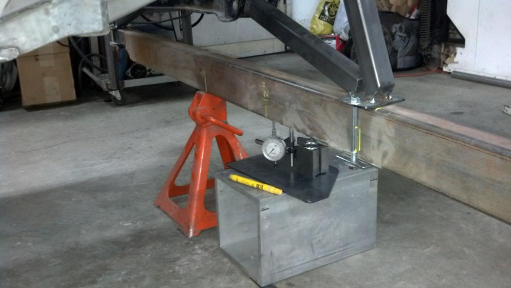
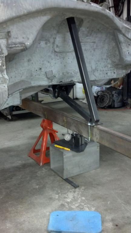
Front setup showing jackstand central pivot, dial gauge and front jig
Front setup with 1.5" x 1.5" x .125" tubing jig.
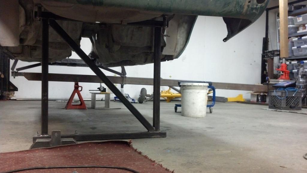
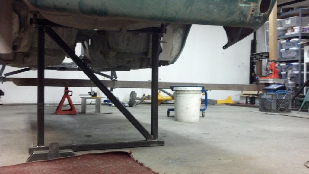
The 2 x 4 x 1/8 steel beam loaded, you can see the jack is extended and the 4x4 wood beam coming down from the rafters.
System unloaded, you can see the straighter angle of the beam and the retracted jack. Also note the two 1/2" bolts holding the rear jig to the floor on the left side of the jig. Securely holding the rear jig down is critical.
The chassis scale at the end of the beam (only using one pad), and the 4x4 wood beam coming down from the ceiling. It is MUCH easier and quicker to just extend and retract the jack to conduct a test than it is to manually load and unload weights from the end of the beam. I've performed about 15 separate tests so far in a small fraction of the time it would take to load and unload 200 lbs of weight from the end of the beam. And with more rigidity it can get up over 500 lbs.
-
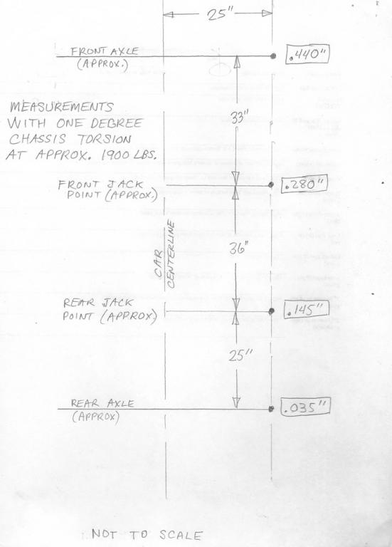
Here are the measurements at different points along the side both in front and back of the rocker. This was with 1 deg twist at about 1900 lbs. It looks like the movement is pretty evenly spread from front to rear.
On closer inspection I am getting some movement in the rear. Not on the rear jig itself but on the body really close to the jig. And also about .077" @ 12" behind the rear jig. So it maybe would have been better to also anchor to the upper rear strut mounts and not just the mustache and inner arm mount points.
-
If you're looking for easy things to do to increase torsional strength try gluing in the windshield. We did that to a chump car to save a gasket and I was amazed at the change in handling. It was similar to what you'd see with a strut tower bar. For fun windshield related trivia, aluminium and glass have almost identical Young's modulus and density. Glass has a yield strength about 10 times higher than plain aluminium and obviously less allowable plastic strain. A 5 mm windshield is equivalent to an almost 2 mm thick steel sheet.
Cary
Yes, the GT40 has a triple laminate windshield that is a definite part of the rigidity of the chassis.
Wonder if lexan comes close?
More on the testing on Sunday.
-
It is possible I'm using the wrong welding technique. I did 3/4" stitch welds but left no gaps between them. Welding 3/4" beads then leaving a 3/4" gap, then another 3/4" bead, then a 3/4" gap. Then when a full section with gaps was done and cooled off going back and welding the 3/4" gaps so the weld ended up continuous on each section/area. Thinking back the original plan was small stitches spaced with bigger gaps between. Then the plan changed to the full weld to effectively "seal" the seams as it would be a PITA to reseal the chassis after burning all the existing sealer out. But more is not always better.
I think it's problematic adding tubing for chassis rigidity. If it's done it has to be well thought out and the best way would be complete from front strut towers to rear strut towers.
Something like this... http://s160.photobucket.com/user/psanders240/library/BSR-260Z-IMSA?sort=3&page=1
This car is probably getting up in the 6000 lbs/deg range.
There may be some benefit to a single tube across as a STB, and a triangulated one to the firewall is even better. (Where the bottom of the cowl structure perpendiculars into the firewall is pretty strong.) The key is STRAIGHT tubing. Bends or kinks defeat the whole purpose. It's too much force and too small of a movement you are trying to hold rigid. This is difficult with a Z because the valve cover sticks up too high. There have to be rigid "raisers" on top of the strut towers so the tubing can go straight across.
Out to the garage now to unbolt and rebolt to check repeatability and also to get some readings at each end of the rockers as requested. The cage isn't going in until the seat gets here next week, then there will be another test.
-
My only complaint with your fixture is loads should be put in via the strut towers with the suspension. Take a look at this post for what I'm talking about. http://www.locostusa.com/forums/viewtopic.php?f=36&t=3241&start=75
Did that in the front but not in the rear using a jig but not the suspension itself. Wanted to eliminate the bushings from the test. The jig bolts to the strut tower top and the inner pivot of the lower front arm (front crossmember in place). Most of the load it going to the strut tower top.
-
Pics when I have time and maybe Solidworks models of the jigs. This project did not take all that long. Not counting design time probably 8 hours tops to build the jigs, and the weighting method makes testing much easier and more accurate. The only expensive part of the equation is the chassis scale, and with a longer beam you could test with lower weight and a good bathroom scale might be adequate.
I haven't looked closely at a 240Z recently so can't discuss the differences although I am aware there are some. There are even notable differences between the '75 and the '77.
-
Looks like a lot of work to generate what are essentially just two data points. Then a big leap to draw a very broad conclusion. An R&D firm would go out of business quickly using this methodology.
What's the error in your measuring instruments, for example? 0.5 degrees is difficult to measure. You could have a loose bolt here - "The rear is solidly anchored to the concrete, bolted to the mustache bar and diff mount brackets, two studs and four bolts" - giving some deflection.
It's an interesting area that could use more data shared (the racers are still keeping their secrets) but reproducibility is important. No way to tell if your work is valid.
Edit - didn't mean to sound so negative. I've done some R&D work though and it's easy to get misled on why the numbers change. If you can reproduce the work using the same tools, you'll at least get a better idea of the quality of your measurements. For example, put the car back on your measuring frame and see if you get the same numbers. Take it off and put it on a few times and see what you get.
I hear you.
But I think torsional rigidity is maybe the one key factor when it comes to chassis suitability. There is no standardized test for say beaming. And weakness in beaming would show up in torsion.
In the past on the torsion tests I've done I have experienced several problems with repeatability. With this new rig took the time to address all those problems. Specifically the rear jig being rigid. The accuracy of all distances. The tightness of all fasteners. The accuracy of the weight and it's placement distance. Rear rigidity was confirmed with the dial gauge, less than .002" of movement.
The dial gauge has .001" increments. Half a degree at this radius is .105". 200 lbs before welding pushed it to .105". After welding 200 lbs goes to .123" a difference of .018" All tests were repeated 3 times or more and all went to + or - .001" compared accuracy. I can try unbolting everything and re-bolting.
I can agree though without going back to the before welded condition (which isn't possible) that there could be some overlooked variable. In addition the sample size being only one is not that great.
I don't think this steel is hardened by treatment, but I'm sure it's a harder alloy than say 1018. The HAZ will cause migration of alloying elements. The HAZ of this type of MIG weld (3/4" long stitches) compared to a spot weld is probably 4 or 5 times larger. Not necessarily hotter just way larger because of the time duration of the weld. And it could be hotter also if heat soak is considered.
All that said can agree though, take it for what it's worth. But for all the trouble and expense of seam welding it seems like it should have gone in the positive direction. Anything negative or neutral for me says it's not worth it.


Spring Question With Shortened Struts.
in Brakes, Wheels, Suspension and Chassis
Posted · Edited by Chris Duncan
Just need to run this by the forum to see if my thinking is correct
'75 Z. Shortened all 4 strut housings by 2" and put Bilstein Sport struts (34-184530). I shortened the struts above the spring perch and left the perch in place.
So using the existing spring does this not increase the spring rate just because it is compressed 2" more just to install it on the strut assembly?
What has happened is that it had stiffer springs when I got it and now that they are compressed 2" more at full strut extension the car is not sitting at or even near the middle of strut travel.
This is a Chumpcar so you can't just buy new springs or put threaded perches. Need to use/modify the existing setup.
So do I start cutting off coils or do I try to shorten the spring with the oven method shown in "How To Make Your Car Handle" by Fred Puhn?
What if a stock spring was used without cutting it at all, would it approach coil bind with the 2" shorter installed height?