lifeprojectZ
-
Posts
49 -
Joined
-
Last visited
-
Days Won
2
1 Follower

lifeprojectZ's Achievements
")


-
Got my own tire sizes wrong. They are 255/35/18 on front and 295/30/18 on rear.
-
Very interesting to think about that. I've not seen the topic discussed before, but haven't been with this forum for very long. I would think that the change in polar moment of inertia with setting the engine back would be very minimal and have an unnoticeable effect. The Z cars are already extremely nimble with such a short wheelbase. Personally, I can understand and appreciate much more the effects of understeer / oversteer that go along with front or rear weight bias, respectively. However, I'm not sure that I would notice it myself in a 47/53 car or a 53/47 car during normal or even moderately aggressive driving. Maybe? I am sure someone who track drives a car regularly and then makes a change affecting that car would notice it. In my case, I am just shooting for a target that I think is worthy, but I will end up dealing with whatever it turns out to be, and hopefully enjoying it regardless! Definitely a consideration for me. I went with 255/40/18 on front and 295/35/18 on rear. Both sizes are 25.0" diameter, and I felt that was extremely important for the balance of the car lowered 3". I like the tire width proportions as viewed on the bare chassis, and I think I will like them even more with the Datsun body over top. My biggest concern at the moment is my scrub radius at close to 3". Is the car going to scramble out to either side when I step on the brakes at high speed? I could reduce that somewhat by using 295/35 on the front as well, but I am not ready to do that until I drive the car quite a bit and find that change necessary. I am however leaving enough inboard space to fit the 295's in case I want to do that in the future. More on that in an upcoming post on Ackermann measurements in my project thread.
-
AME complete chassis '77 280Z
lifeprojectZ replied to lifeprojectZ's topic in S30 Series - 240z, 260z, 280z
I planned on shimming a little bit. I spec'd the outer width of the frame at 51.25" because I measured a repeatable 51 5/16" between the the lower lips of the rocker panels on both sides. But AME failed me. The frame ended up at 51 - 51 1/8" width, so it will take more shimming, but an acceptable amount. The only part of the chassis that will be visible from the outside of the car is 1/4" providing a smooth straight line underneath the rocker panel drop lips. On the inside it is a different story. I will have a section of tubing dividing my right and left feet, but I finally accepted that after realizing my feet don't dance around too much while driving, and the tube won't affect my application of brake or clutch. Me too. I'm not sure yet. But it seems I have just about reached the end of the road on my adjustments and measurements. More on that in the next post. -
AME complete chassis '77 280Z
lifeprojectZ replied to lifeprojectZ's topic in S30 Series - 240z, 260z, 280z
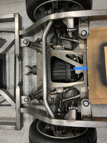
No other way! Anything aftermarket has to be meticulously scrutinized! A few years ago I bought some rear lower control arms from TTT (when I still thought I would just modify the original suspension), and when I received them, they looked beautiful and well made. Until I set them on machine blocks and found one of the arms slightly distorted. A lot of quality control and engineering is needed to produce dimensionally accurate parts that are welded, bent, machined. Absolutely, and I did exactly that where I thought it mattered. I first determined the center of the REAR suspension cradle by using lasers on the upper control arm mounts, and then marking the center on the cradle. Then I determined the center of the front suspension using lasers through the lower control arm mounts that you see welded into the lower cross-member, and marked the center on the cross-member. Then I ran the laser through the front and rear suspension centers, and proceeded to check alignment of the lateral frame rails. That is how I confirmed that the front X-member is off at a very small angle. I also used that centerline through the front and rear suspensions as a reference for the laser I placed outboard of my front/rear tires to check toe before taking ackermann angle measurements (future post). It is a bit time consuming to do it that way, and my (future) three laser set-up will be quicker. I hadn't thought of that. Though I am not sure how I would keep the wheel hub stationary vertically and still allow freedom of steering movement for the measurement. Yes you got it. AME aligned the front and rear suspensions together pretty well from what I can tell. But the front inner frame rails, and the lateral outer rails do not run parallel to that centerline. So my options are to either shim the body before welding it onto the chassis such that it is parallel with the suspension centerline, or to correct the chassis so that the suspension centerline runs parallel to the frame rails. With the three laser set-up I referred to, I will get more accurate and final measurements, and will make a decision at that point. Here is a photo from above at the rear suspension. You can see it is offset laterally in the mounts. That will always bother me if not corrected. No, they are definitely aftermarket for custom tubular control arms. They are some type of hard plastic like Delrin / urethane with very little material between the two tubes. I don't think I am getting any flex from them especially since I take the bump steer measurements with unloaded suspension (no spring). They are in inches. I tried to take measurements from 2" droop to 2" of bump, although I don't think this range of movement is necessarily realistic, and it was difficult to achieve most of the time. In bump, my maximum on driver's side was 0.016" toe out at 1.75" bump, and 0.032" toe out at 2" bump on the passenger side. The difference between these two is likely due to minor differences in the location of the inner tie rod pivot (at the steering rack clevis). I tried to get both sides as even as possible, but it is difficult and I finally settled for good enough. At least I have toe out in bump and toe in in droop. That is better than the opposite. But I think these numbers overall are pretty low. I can appreciate the value in this if I had the software and training to do it, but I have neither. As you'll see in a near future post, I made a lot of "educated" changes to the steer arm pivots to study the effect on the ackermann angles. Good engineering design work would always include test validation anyway, so I am just skipping to that part. Great dialogue!
-
AME complete chassis '77 280Z
lifeprojectZ replied to lifeprojectZ's topic in S30 Series - 240z, 260z, 280z
For some reason every picture I post comes out smaller than the picture file when viewed on my PC. If anyone knows what I am doing wrong, I would appreciate some guidance! -
AME complete chassis '77 280Z
lifeprojectZ replied to lifeprojectZ's topic in S30 Series - 240z, 260z, 280z
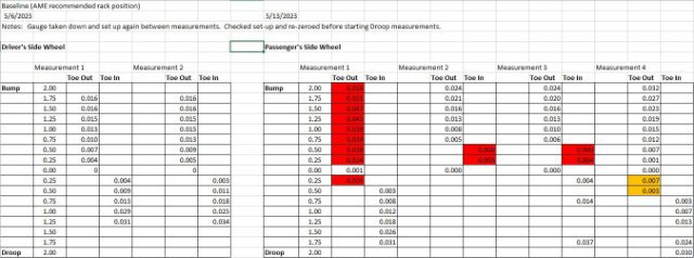
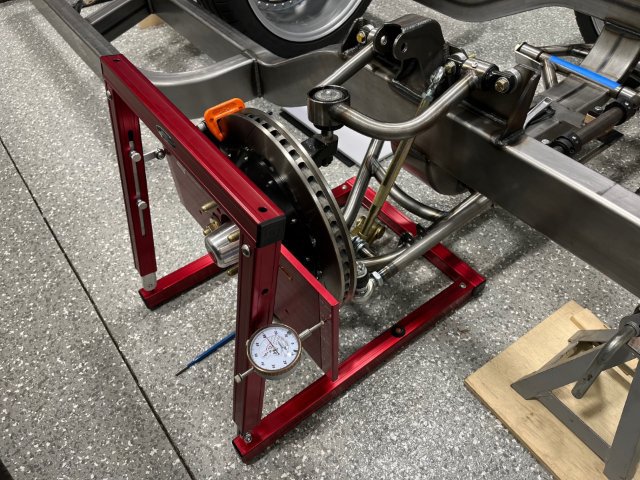
Bump Steer. I was more excited to check and adjust Ackermann geometry, but it seemed logical to first get a baseline bump steer measurement with the steering rack simulator set to the rack dimensions recommended by Art Morrison (AME), and mounted in the position recommended by AME as well. So I bought the Longacre bump steer gauge from Speedway Motors which had the lowest price. I figured that with my front suspension and independent rear suspension, I will get quite a lot of use out of this gauge so it was worth the investment. Quite pleased with the quality manufacture of this instrument, although I did have to replace a spacer with a shorter one to prevent the roller on the one side from tracking off of the measurement plate during measurements. I found the bump steer measurements more difficult to take than I had expected. Some of the difficulty was due to the fact that my suspension arm bushings and ball joints are brand new and tight, so the arms do not want to flex easily, and tend to lift the unloaded chassis when they are bumped (lifted up). So I had to add weight on top of the chassis, otherwise this movement throws off the measurements. I also found that the gauge itself has to be aligned very carefully and meticulously studied during the course of measurements, otherwise the dial indicator can run over on the radius of the edge of the plate, and give a faulty reading. Finally, any touching of the jack or anything else to the bump steer gauge will move it and throw off measurements. I also had to put C-clamps on my rotors to keep the measurement plate from rotating, since that would also, yes, throw off measurements. So there was a lot to keep track of and fix before I could get reliable, somewhat repeatable measurements. The dial indicator itself was also difficult to zero, and so I had to repeat measurements several times until I felt they were reliable. The numbers I highlighted in red and orange, I believe were influenced by one of the above factors, and are not accurate. Fun fact: I used the OE Datsun jack underneath the lower ball joint to bump and lower the suspension. Just turned it by hand. In conclusion, what AME says is zero bump steer in their sport front suspension is not actually zero. But apparently it is pretty low and would not be noticeable in a street car according to some sources I have read (Woodward Steering tech article, and "How to make your car handle" by Fred Puhn). After I was satisfied with these measurements as a baseline, I decided to move on to the Ackermann geometry.....coming up next.
-
AME complete chassis '77 280Z
lifeprojectZ replied to lifeprojectZ's topic in S30 Series - 240z, 260z, 280z
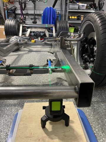
Progress on frame alignment checks, bump steer, and ackermann geometry measurements. Have been letting savings recover this year after the purchase of chassis and wheels in 2022, so with that and the rest of life happening, I have spent countless hours staring at the chassis (from many different angles), pondering the possibilities, and taking measurements which don't cost a lot of money. I will update on my progress over the next several posts. Hopefully some will find this interesting and/or useful. Would love to hear from you if you do, and any similar experiences. Frame Alignment Checks: Of course I can't just assume the Art Morrison chassis was built square and to my specs, so I have to check every part of it. I purchased a second auto-leveling cross-hair laser for about $60 on Amazon, and now am able to perform some interesting checks. My plan is to purchase a third, and mount all three on a 6.5' section of extruded aluminum rectangular tubing. With that, I can locate the center of the chassis, and check both sides at the same time. But with the two lasers (and also some other measurement techniques), I was able to verify that the front cross member of the chassis which holds the lower control arm mounts, is slightly crooked in the frame. Or, you could say the frame is slightly crooked with the front cross member. This is why the rear suspension cradle was mounted 1/2" offset to one side at AME. Something I noticed on about day 3 after receiving the chassis. I called back in to AME to discuss this, and was given a load of B.S. Long story short, I will have to correct this eventually, and I haven't put together the best plan to do it just yet, since the upper control arm mounts were welded on (crooked) but in alignment with the lower cross member. To explain this in a different way, if I were to take the Datsun body and weld it over the side rails of the frame as planned, the track of the car would not be square / parallel with the body. It would be slightly off at a small angle. I think this has to do with the order in which AME laid out and welded all of the chassis components together, and which components they held as critical references. Of course, they will never admit that or that any problem exists. The salesman had the nerve to tell me that their chassis is held to higher tolerances than an OE chassis. Photo below shows two lasers aligned over the lower control arm mounts. I spent countless hours checking this alignment with steel rules, levels and squares and different methods to make sure the lasers were centered on the tubes until I was satisfied that I had it right. So that is where I stopped, and where I will return after I finalize the steering geometry.
-
Really appreciate the responses and would love to see more. Very interesting to see what others have done and even more to know why. I may have to end up doing that for header clearance if nothing else, but am hoping to keep the firewall as original as possible. One of the big unknowns is how my weight distribution will turn out given the custom chassis, steel cage IRS with the Dana 60 differential, roll cage, etc. I hope to get it close to 50/50 but I won't know until the car is complete. Looks like I'll be getting an LS long block within the next 4 months so I'll be able to see more clearly how it will play with the rack position and firewall. Another benefit of moving the engine/ trans back would be getting the shifter in a better location. Right now I'm leaning heavily towards the Tremec TKX instead of the T-56 Magnum F as I just learned it is 40 lb lighter, and I don't need two overdrives. But the shifter is a few inches further forward. I just don't want to end up weight biased heavily to the rear of the car.....but not completely sure of that either.
-
Thank you! Is your car lowered and if so how much? Another concern I have....I had my chassis built around having the body lowered about 3" from OE spec. 51.5" roof height down to 48.5" roof height. I'm a bit concerned about fitting the LS in, keeping 4" ground clearance with the pan sump, and not having to modify the hood any. Hoping to keep original hood contour. I forgot to consider engine height before settling on the ride height for the chassis. I'll have an LS long block within 6 months, but I can't stop thinking and dreaming about how this is all going to work out.
-
I have searched and can't find good close-up photos or measurements showing me the following in LS Z-car installs: 1) Distance from rear face of block to firewall. 2) Fore/aft positioning of OE steering rack centerline relative to engine damper / oil pan. Is the damper completely behind the rack centerline, or are you lining up the centerline of the rack with the space between the rear of the damper and the front of oil pan? I am working on a full custom chassis install in my 280Z, detailed in the member's projects section, and looking right now at the steering rack positioning and engine mounting. I don't have the engine yet, but hope to order a long block later this year. Am curious to know how mine is going to end up relative to others who have kept the OE steering rack position and are using aftermarket designed engine mounts for the LS in the Z car with OE engine bay frame rails. Thanks in advance for any info you can share.
-
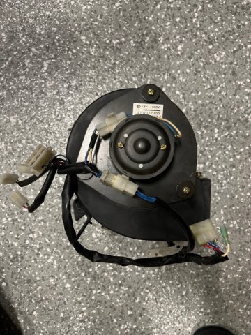
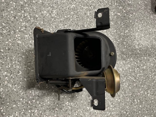
$80 including shipping anywhere in the continental US. Boxed and ready to ship. It worked fine last time I tried to use it (22 years ago when I drove the car from San Jose, CA across the US).
-
AME complete chassis '77 280Z
lifeprojectZ replied to lifeprojectZ's topic in S30 Series - 240z, 260z, 280z
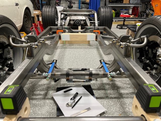
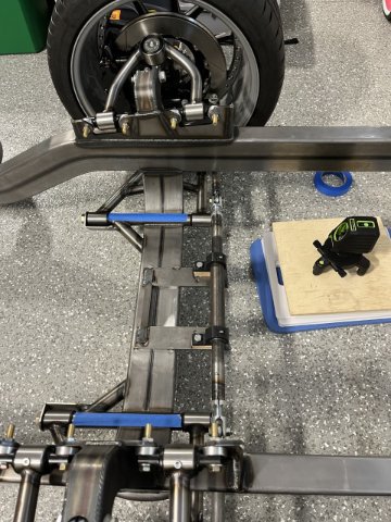
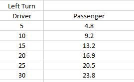
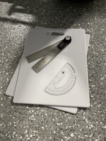
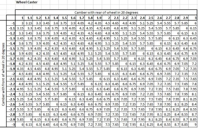
Laser planes, cutting boards, and bump steer. Not much physical work on the project over the past few months, but a lot of inspecting, thinking, and obsessing over minor chassis alignment issues, steering issues, and how to fix them or live with them. I finished a steel brace for the adjustable steering rack simulator and tack welded it to the front cross member. Now I can turn one wheel and the linkage turns the other without ripping itself apart (like the wood bracket I initially wasted my time with). The purpose of doing this was to determine the ideal rack positioning, pivot-to-pivot length, and rack gain / ratio before ordering a JL series rack from Woodward steering. I'm starting with a baseline of the rack position and specs that AME gave me, and will adjust from there to get positive ackermann geometry and minimal bump steer. They specified to locate the rack centerline slightly in front of the steering arm links, and I learned from Woodward that this is a big mistake. It results in anti-ackermann steering. Although I haven't set up to measure the angles precisely yet, I think I can see it by eye already. Rack height is probably going to stay at the AME spec. I can't go much lower if at all, or the rack boots will scrub excessively across the lower control arm mounts. Going higher would just limit how low I can mount the engine, and I don't see any benefit from raising the rack anyway. I can possibly move it back 1/8 - 1/4". But likely where I am headed is designing custom steering arms which are longer than the Wilwood ones and possibly move the link connection further outboard as well. I do have some clearance with the rotor to do that. So I am fabricating some simple extensions that I can place on the ends of the steering arms to move the linkage joints further forward and forward+outward and see how that affects my Ackermann. I calculated the theoretical ideal ackermann angles with a wheel base of 90.75" and a wheel pivot to pivot distance of 48.7". This is the distance between the spindle axes of rotation where they intersect the floor, taken from my scrub radius calculations. I probably should have extended the wheel base value due to caster, but didn't think about that until later. These are close enough: So thinking about adjusting toe settings, measuring camber and caster, I turned my attention (no pun intended) to a set of turn plates. I found cheaper ones ($200 range) that have a simple pivot in the center but allow no fore/aft or side-to-side motion for scrub. More expensive ones $800 - $1000 that do allow that motion. But the best alternative I found was on a Youtube video with a guy suggesting to use two poly cutting boards stacked together. So I bought four cutting boards on Amazon for about $6 each, and some 1/8" thick rubber matting to place between the floor and the lower board. Since I am dealing with a bare chassis with solid rods in place of shocks, this will work quite well for me, I think. With these, my tires will turn easily without restriction, and I hope to be able to measure the angle one of several ways. For the caster reading, I am going to mark several 20 degree lines on the lower board, and then I can visually align the upper board with the lower. That should be quite easy. I didn't know until recently that caster is found through a simple calculation from camber angles taken at -20 deg and +20 deg rotation, so I went ahead and made a look-up table to simplify finding caster. I can easily measure camber with a straight edge and my Wixey digital angle gauge. I soon realized that the best way of checking the alignment of my chassis as well as toe would be to use laser planes. So I bought a $55 Huepar laser level and a mini tripod from Amazon: After playing with this quite a bit, I realized quickly that I will need another one (although two more would probably be ideal). With two lasers, I can get the planes parallel and shoot them through the lower control arm mounts in the front cross member, and find the true center of the chassis. I can then confirm the upper rear shock mounts are aligned to the center, and I can also align the rear suspension in the chassis. I am hoping that I find AME already did that. I can also set toe of each front wheel with respect to the centerline. The laser plane projection is about 1/16" thick, which seems to be adequate for measuring toe to 1/32" using a steel rule with fine etched markings every 1/16". For this year, my goals are to get the steering figured out and order the rack, remove and POR15 all of the suspension arms and rear IRS cradle, and to get and mount the universal poly tank from Tanks, Inc. I expect 2024 will be the year of the engine + trans.
-
1977 280Z Front/Rear Anti-Sway Stabilizer Bars
lifeprojectZ replied to lifeprojectZ's topic in Parts for Sale
Yes. -
AME complete chassis '77 280Z
lifeprojectZ replied to lifeprojectZ's topic in S30 Series - 240z, 260z, 280z
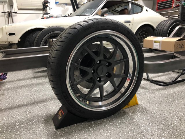
Here is a view of the left front and rear wheels with rotors mounted. The front rotors ended up further inboard than the rear. Not crazy about this aesthetically, but nothing I can do at this point. A decision I made on the rear wheel offset makes this look more exaggerated and makes the rear lug nuts stick out slightly more than the front. If I could do it over again, I probably would have made the "front-spacing" of both the front and rear wheels the same rather than going for a 1/2" deeper dish on the rear which is what I did. Front wheels are 9" wide and rear wheels are 10.5".
-
AME complete chassis '77 280Z
lifeprojectZ replied to lifeprojectZ's topic in S30 Series - 240z, 260z, 280z