

katokid
-
Posts
51 -
Joined
-
Last visited
Content Type
Profiles
Forums
Blogs
Events
Gallery
Downloads
Store
Posts posted by katokid
-
-
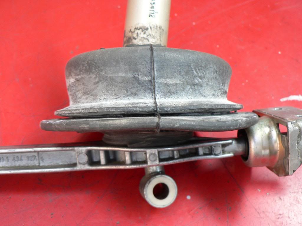
Its the front bush for an RN90 Hilux rear spring 40mm OD
-
Hi all.
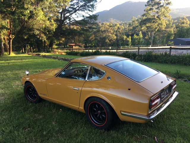
Apologies, I got so caught up in work and my build that I didn't have time to post here. Good news is that the car has been finished for a few years now and is an absolute blast to drive. No real issue to speak of and has been 100% reliable even on the racetrack.
My full build thread here : https://www.viczcar.com/forums/topic/4654-kato-kids-bmw-m3-powered-71-240z/page/41/#comments

-
Thanks for the compliments.
I like detail and love to see it in other peoples threads, no doubt there are some people that can do without the detail but hey you dont have to read it.
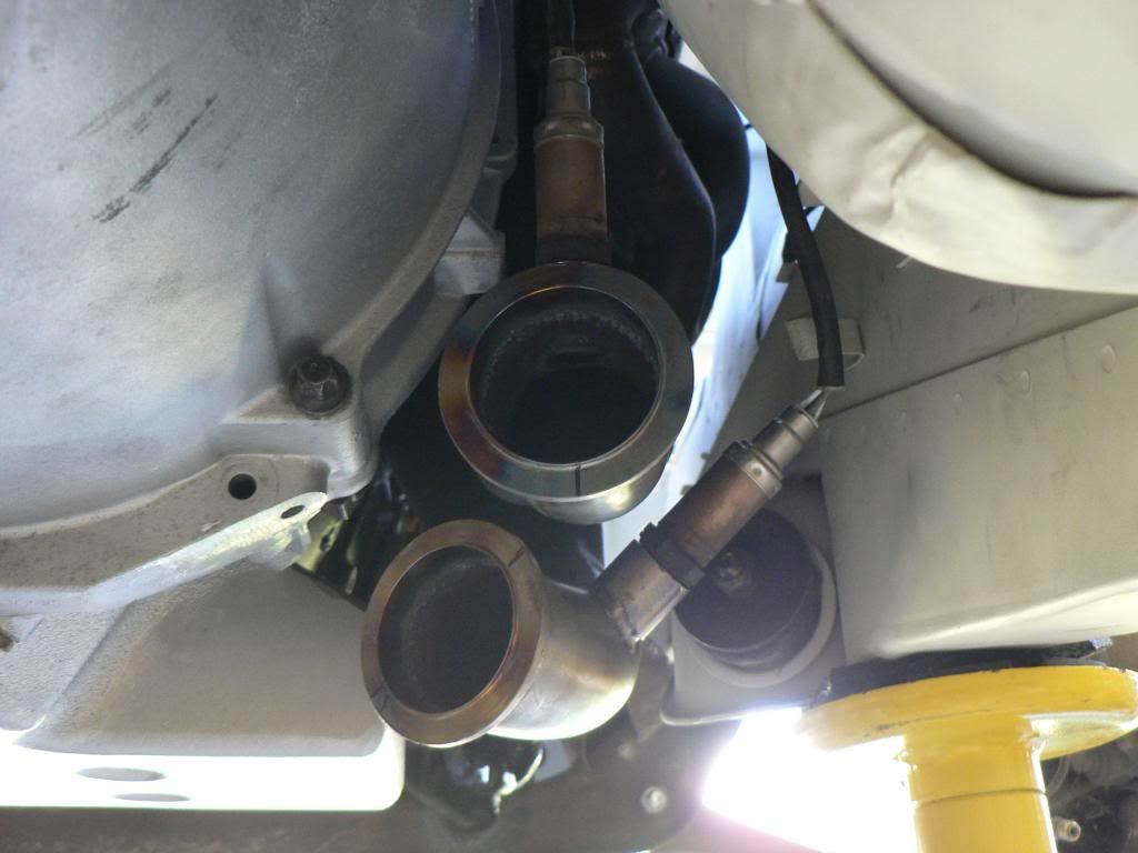
Last bits I had to do before I returned the welder to my mate was the rear mount, the tip and the O2 bungs.
The tip was a matter of measuring and cutting, creeping up on it to get just the length I wanted. I probably should have hung the rear bar on it to confirm it still looks Ok. Also included a shot of the rear mount before I added the tip.....not much room up there but it hangs just right.

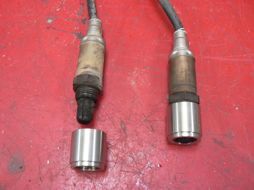
There isn't much room for the O2 sensors and I was going to put them further downstream where I had more room but luckily I did some reading up and they require a minimum of 600 deg C to work properly. They actually have heaters in them to bring them up to temp quickly so they can monitor emissions on cold start. The bungs are the same length as the factory bungs at 25mm and are pretty close to where they were on the factory headers so should be good. Also they must be pointing upwards from horizontal so that the water from condensation on start up doesn't collect and damage them.....the things you find out! -
Thanks for the compliments guys.
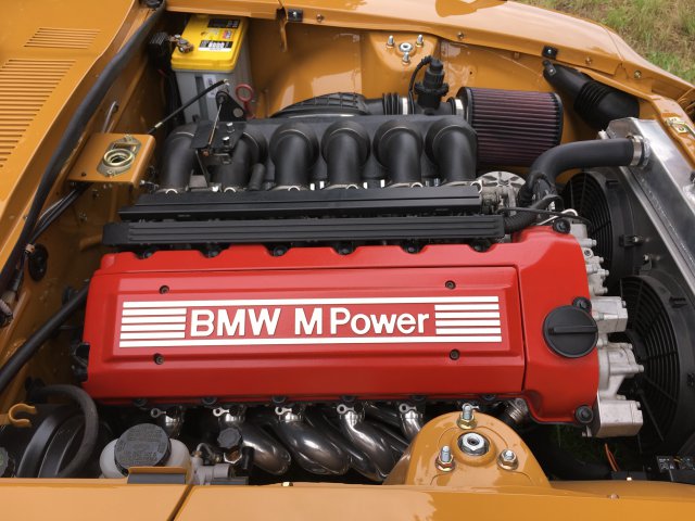
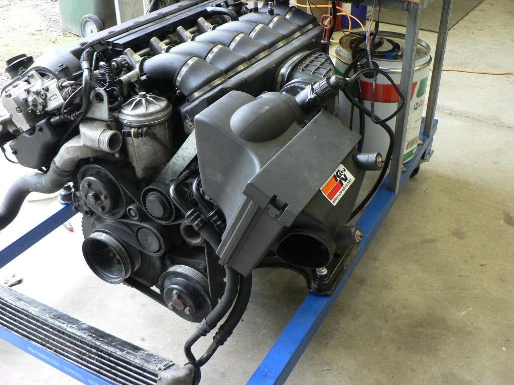
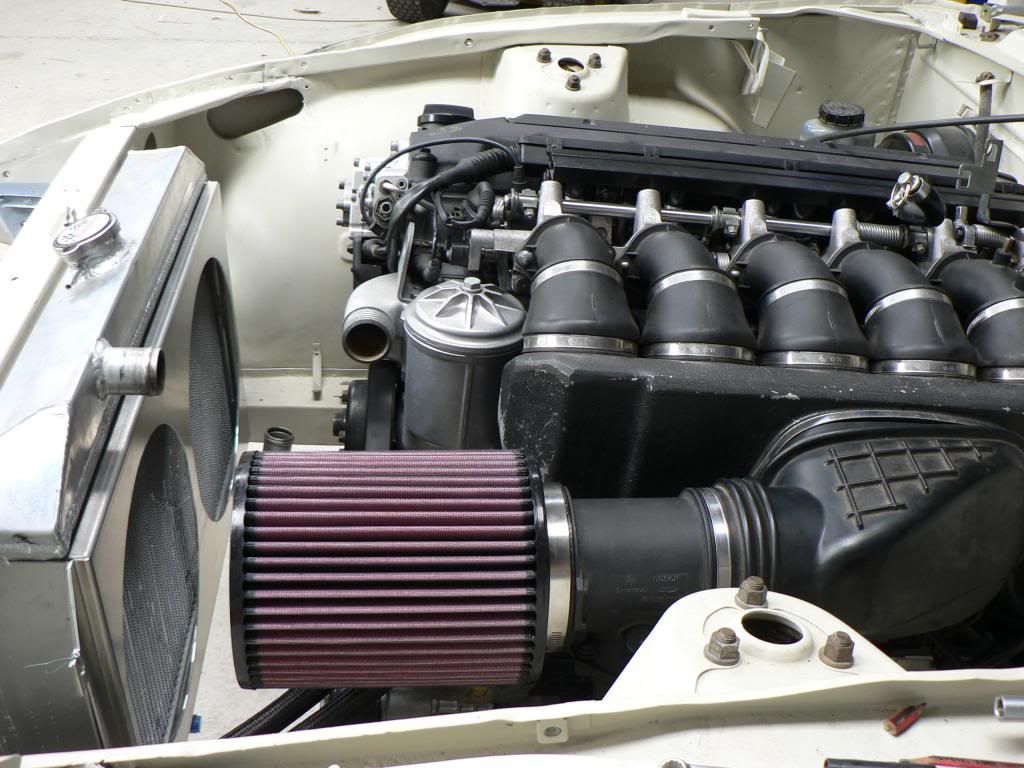
I haven't been completely idle but life and work just keeps getting in the way...I have been plugging away on the air filter and exhaust system.
There was no way the factory BMW air filter assembly was going to fit so I had to find an alternative.
Ended up with the only K&N filter in their range that had the required 92mm ID to match my MAF. Its pretty fugly and far from what I envisaged but it works and I'm constrained by the oil cooler lines that run underneath. There's a bracket which you cant see that supports the MAF and filter coming off the engine mount below.
I thought of running a tube through the radiator support panel and having the filter out front in a set up like the standard 280 arrangement but the hole in the radiator support is way too small and I didn't want to cut it up.As Ive stated previously the factory M3 exhaust system is a dual 2" system all the way and the aftermarket systems pretty much replicate this but go up to 2.25" all the way . Everything I read says that Bimmers drone like crazy with a large single and lose the signature Bimmer note if you go away from duals so I was pretty committed to staying with this format if I could make it fit..... with the condition that I had to have good ground clearance.
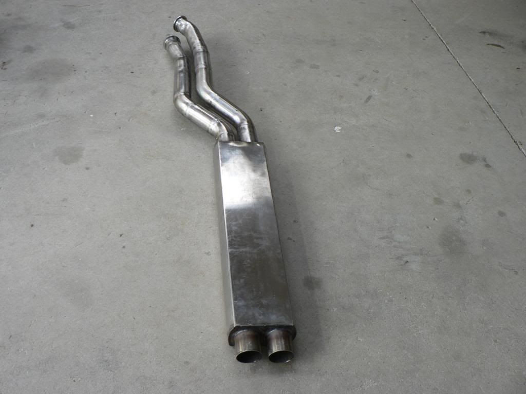
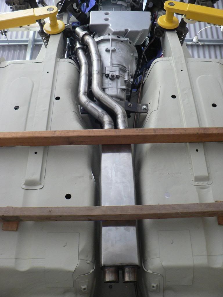
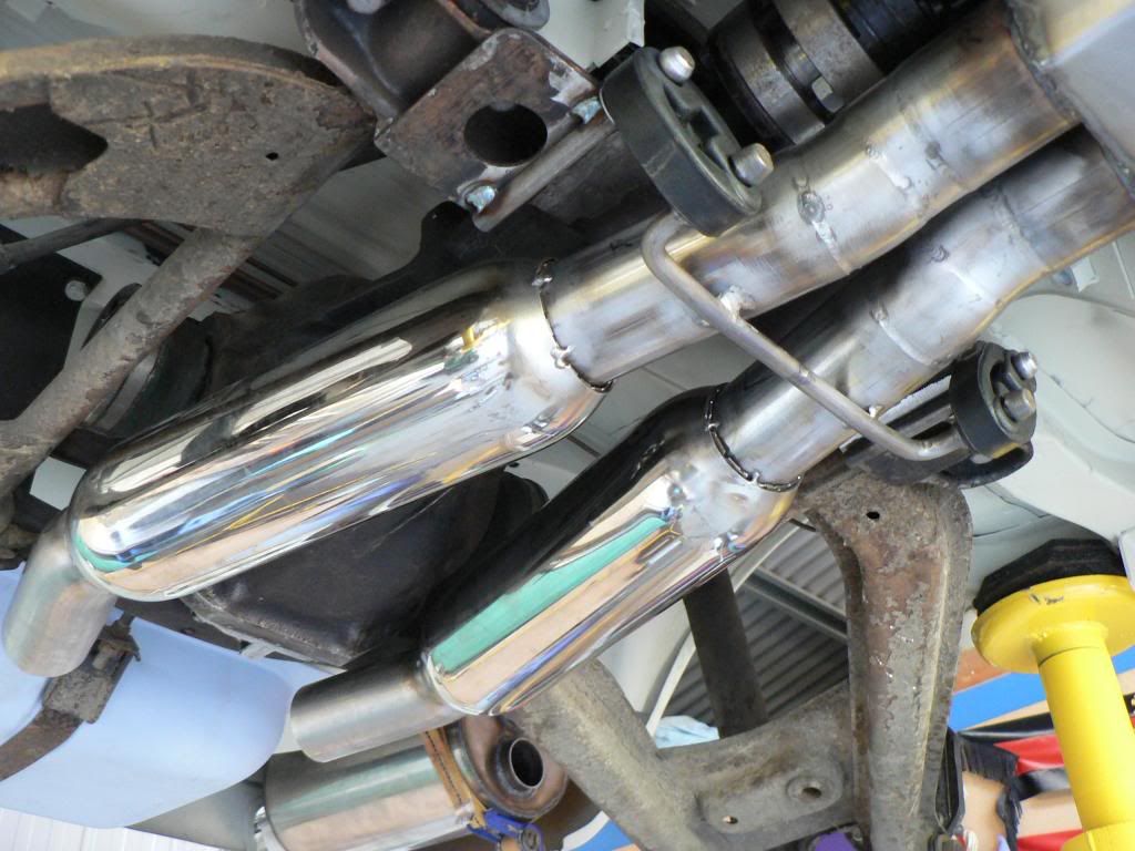
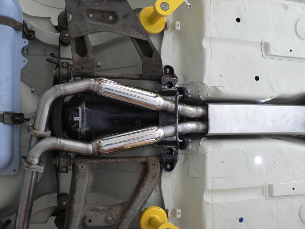
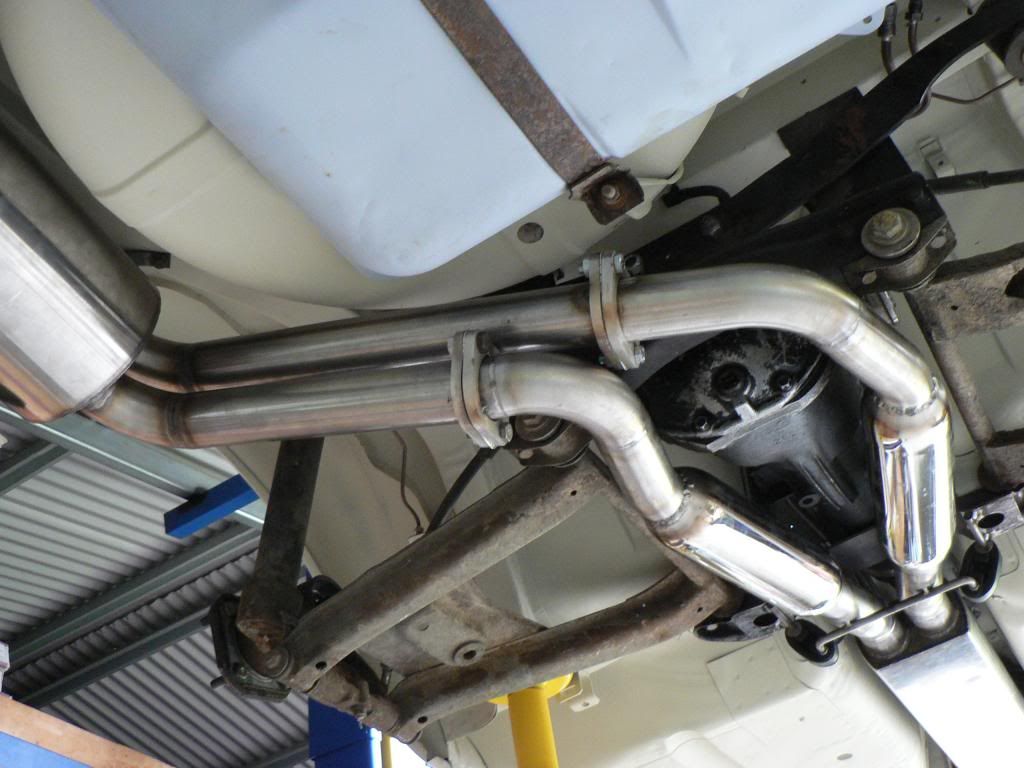
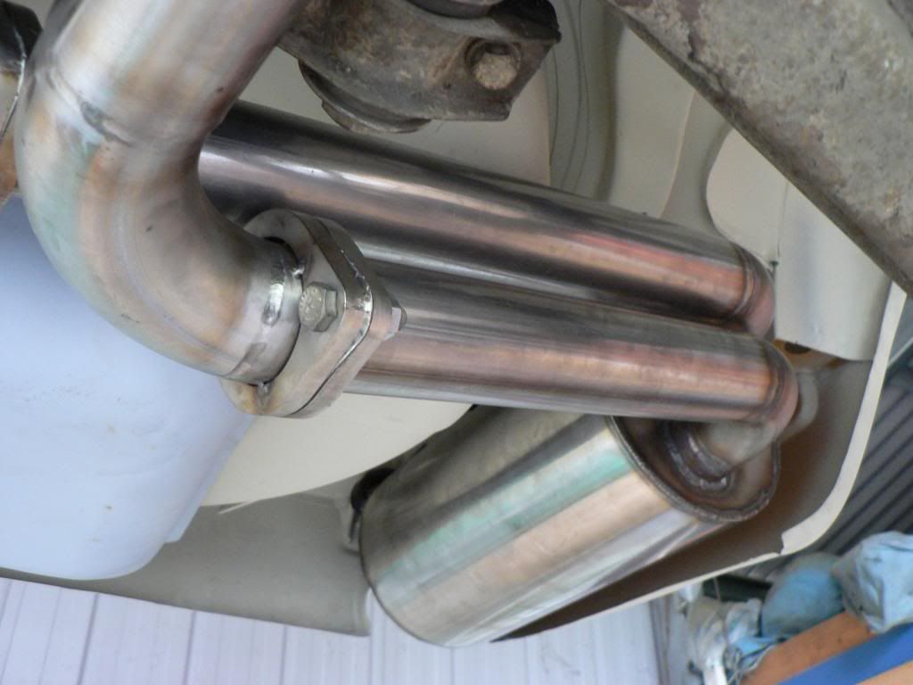
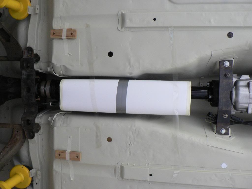
I didn't want to use chambered type mufflers so I need as much length and volume in the straight through designs as I could fit under the car and hope that will get me through rego and still sound good and be nice to drive....we shall see! I had a custom stainless mid pipe resonator and rear muffler built to my plans. Resonator is as long as space would allow, there will be two 12" hotdogs under the diff and then into as large a rear muffler as possible with dual inlets merging internally into a single 3" outlet.
I bought a bunch of 304 mandrel bends, V bands, hangers and other stuff and got into it.
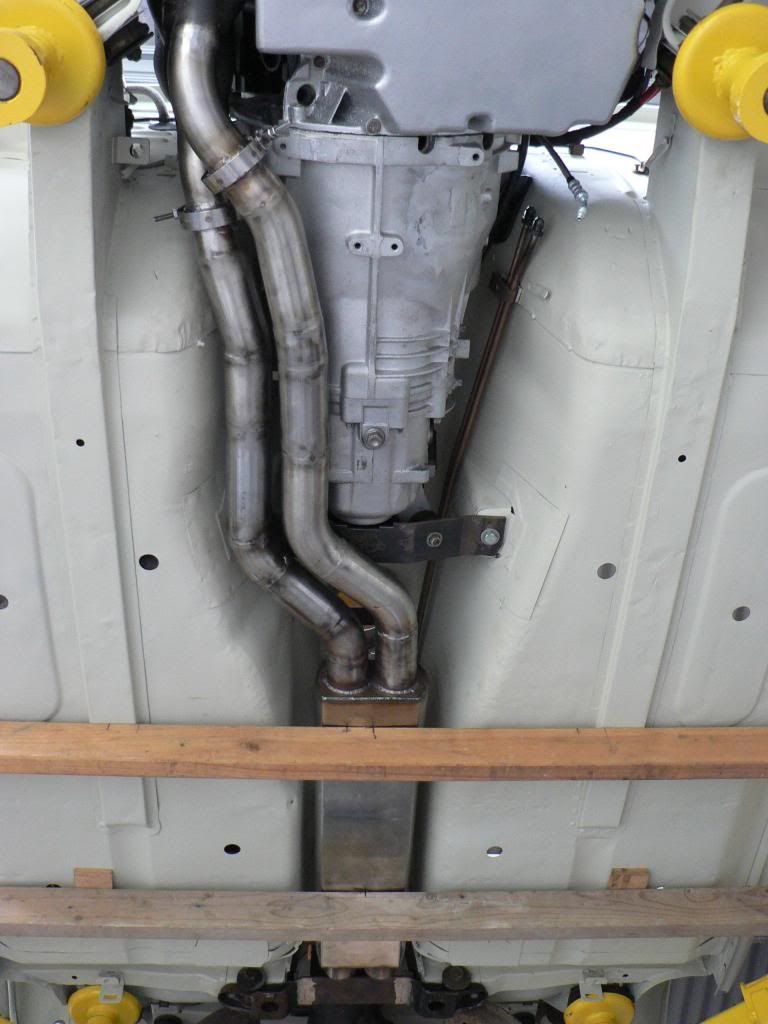
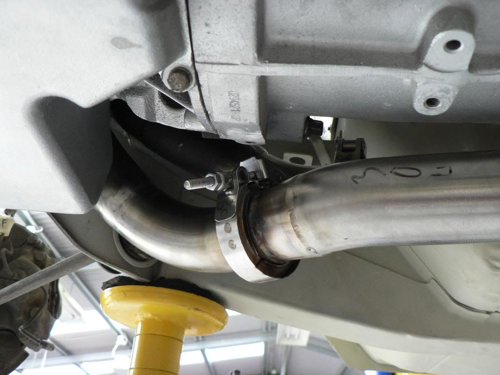
The factory headers are double 3 into 1's with the secondary pipe being 2". In order to be able to remove and refit the headers in the car I needed to have flanges as close to the end of the secondaries as possible, there was little room so V bands were the only way. Down stream from the V bands it goes straight into a 2" to 2.25" cone and then eventually via many bends and sections into the resonator.
The two bits of wood in the photos are there to position the resonator while I built the engine pipe(s) and they sit hard up on the chassis rail for the front one and the back one is spaced down the corresponding depth of the rail so the resonator sits level in the car.
After many hours of work I'm very happy with the engine pipes and the resonator fitment. Ground clearances is not compromised at all ....but things may get a bit warm inside the cabin as it is tucked up very high and close to the tunnel.I lashed out and bought Vibrant Performance V bands from Summit and very glad I did....very well made, full stainless (cheaper stuff isn't) and they have this really cool flip on flip off quick connect feature for the T bolt. I couldn't tell you how many times I have removed and refitted them in the process but it was heaps and they work brilliantly.
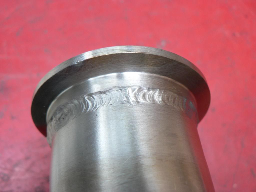
I borrowed a BOC Inverweld 140 http://www.twi-global.com/industrial-membership/industrial-members-showcase/products/boc-inverweld/ which is a small portable machine. Its really a stick welder but can be set up to use as a TIG however it has ZERO features (hand or foot amperage control, pre flow, post flow etc) that you normally find in a decent TIG. I had never TIGed before so figured I would tack it with this and have someone experienced finish weld but after a bit of mucking around and going down to 1.6mm tungsten's I found I could get a pretty decent weld from it so have decided to do it all myself. As long as you get very good joins with no gaps you can just fusion weld with no filler, most of the time I enjoy it but every now and then it gets a bit ugly but Ive learned heaps and pretty confident now.
Ive used generic "Toyota" rubbers which use 10mm push on rods. Ive used cheap mild steel rods for the top rods that have been welded to my modified suspension/front diff mount cross member as they will be painted but had to spend $70 for 10x stainless rods for the lowers. Mounted at 45 degrees it relies on the weight of the system to keep things central. There is some lateral movement as expected but its not enough to be a problem (I think) given the tight tolerances (I'm working with half an inch as minimums) and they are nice and soft so hopefully should provide good NVH insulation.
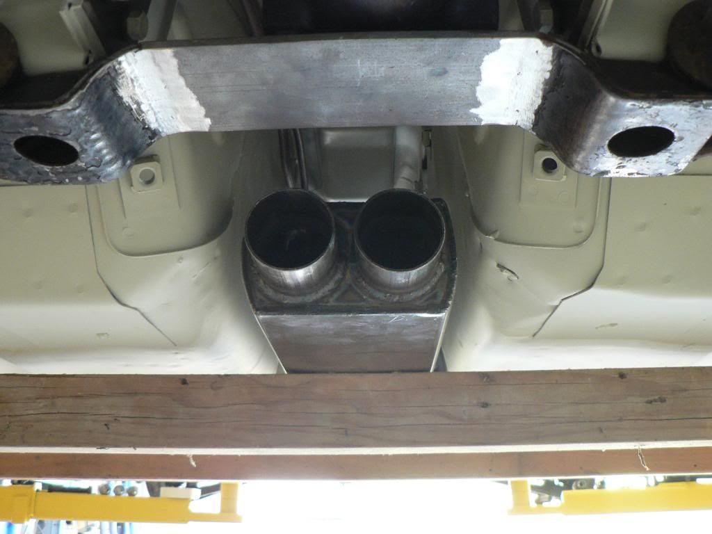
Its not easy to see but there is a step down from the exit of the resonator to the inlet of the hot dogs, required to optimize the ground clearance for the resonator and the positioning of the hots dogs to clear the R200 diff. Also required was the turned in exits from the hot dogs to clear the the rear suspension. The step down loses me some about half an inch of ground clearance but cant be avoided.
Exhaust is virtually finished, just need to make the front mount for the rear muffler and do the O2 bungs.
Its been a much bigger job than I anticipated. Making it a dual system makes it much harder because you have to mirror everything ...if its a single system there is no reference so it always looks right but as soon as you introduce a dual system you can see where things diverge or converge or don't match and look pox if you don't take the time, especially so for this rear section.
If I was doing this again I would do it in mild steel and coat it, stainless is just that much harder to work with. The welding bit is fine its the cutting and fine tweaking to get a no gap join so that you can fusion weld is the really time consuming part as stainless is so much tougher (hardness) than mild.
Anyway I'm pretty pleased with the way it looks....just hope it is quiet enough and sounds good! -
You are building my perfect S30, David.
When you're done it'll retain all the wonderful sounds and feel of the original, while having the response, drivability, and NA simplicity of original, yet turn 12 second 1/4 mile times, rev to the moon, get better fuel economy, and not gain a single pound of weight. Pure tactile and aural bliss combined with supercar performance. Can't think of a more intoxicating Z experience than this one.
Ron, thanks for the kind words.
You've summed up much better than I could the way I feel about this project. I was so tempted to go with a more powerful engine (RB, JZ, LS) but so glad I stayed true to the NA in line six heritage of the early Z's.
I just hope it runs true to your predictions and my aspirations!
Thanks again for the inspiration and help.
-
I'm slowly working away on all the little things before I disassemble the shell and send it to off for final paint.....getting closer.... just the exhaust as the last major piece.
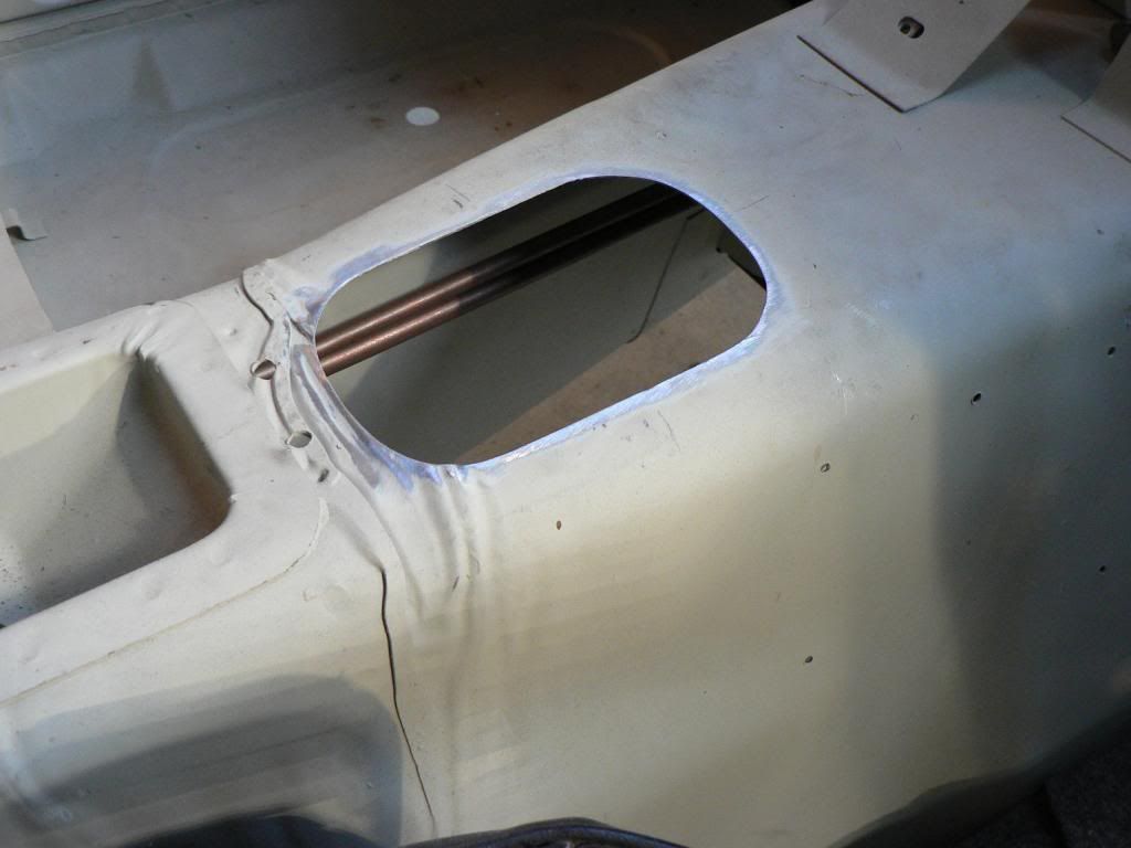
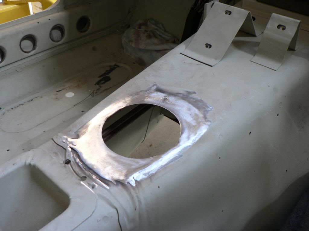
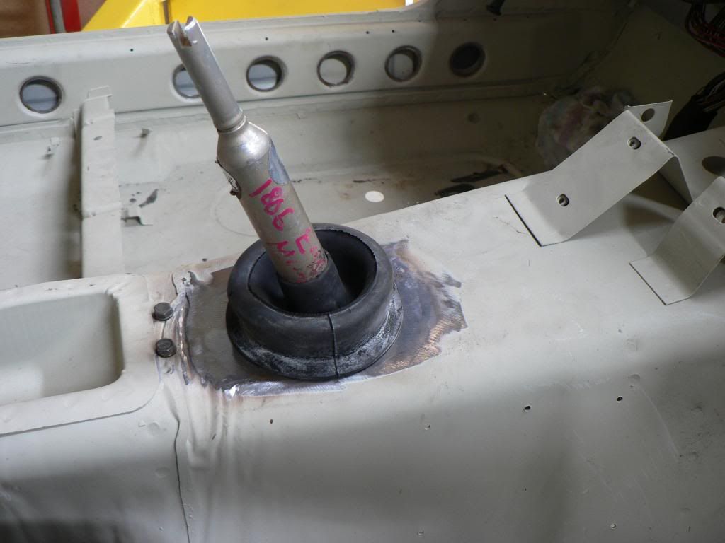
The BMW shifter has an inner and outer seal. The inner seals on the base of the shifter fulcrum and the outer seals on the gear lever and to the body by means of a recessed flange in the boot. No bolts or screws....the boot just pulls through the tunnel and seals very tightly on the recessed groove. Fortunately the original hole in the Z tunnel is exactly the right width for the correct diameter of the round hole that the boot requires so I just had to add a bit at the front and the rear. -
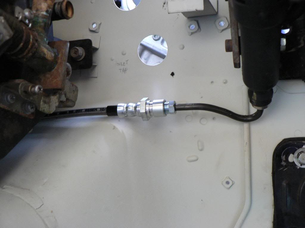
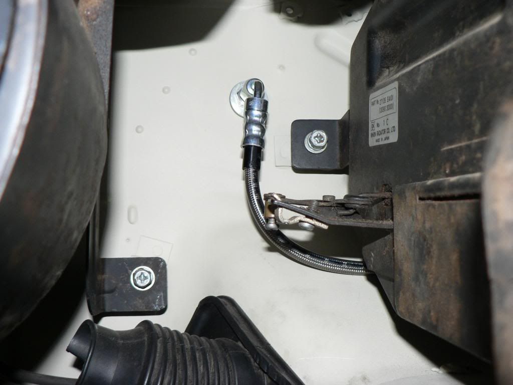
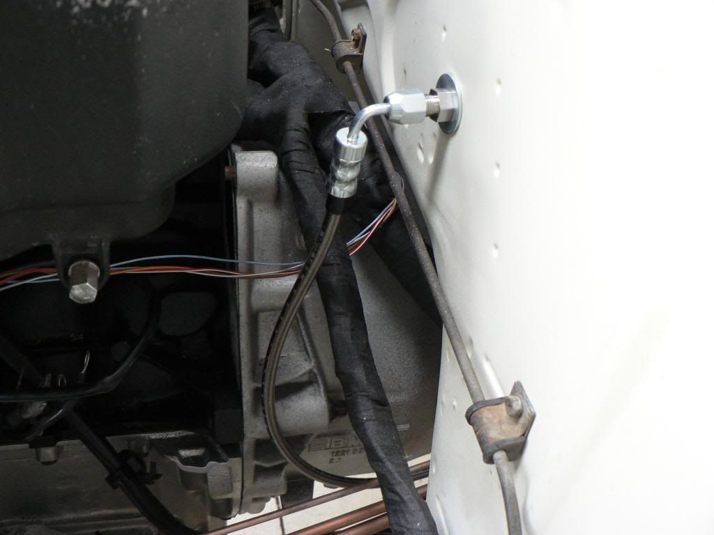
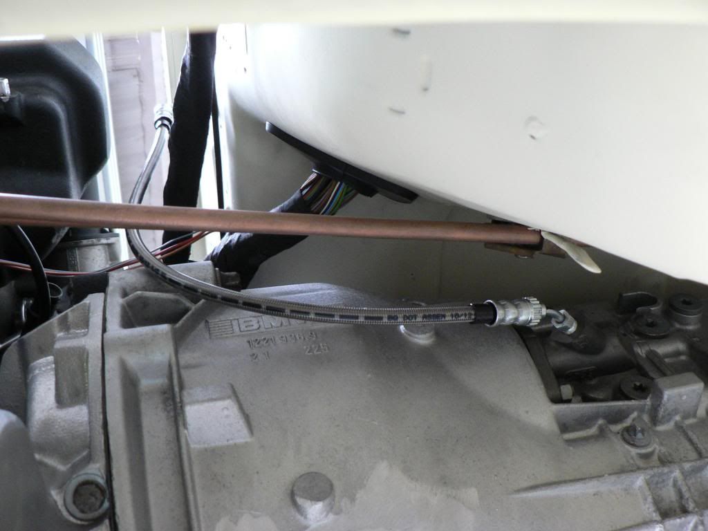
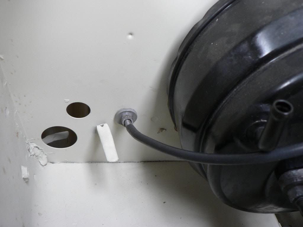
At least the clutch line was cheap. Two sections made up by Better Brakes in Bayswater......one from the master cylinder under the dash then behind the heater box to a firewall fitting which uses the original hole where the choke cables went through. Second part goes from the firewall down to the slave cylinder.
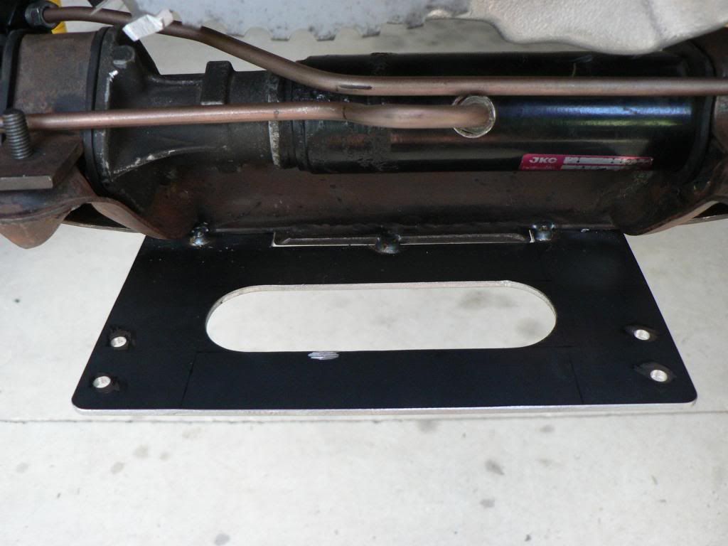
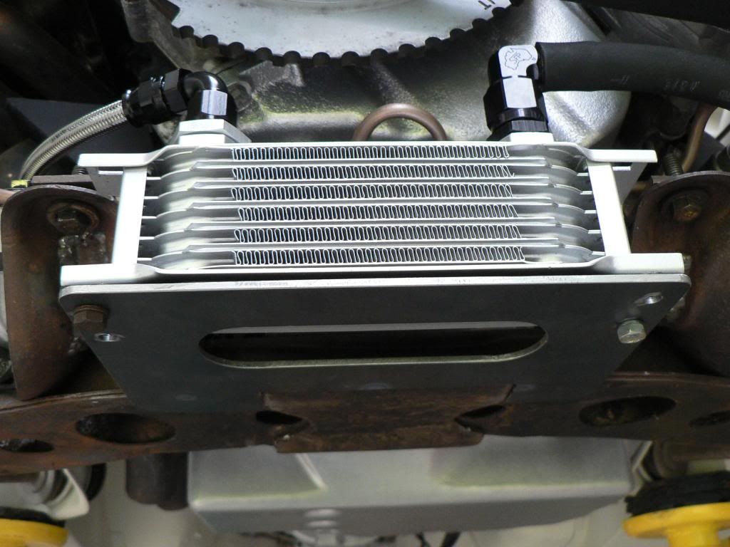
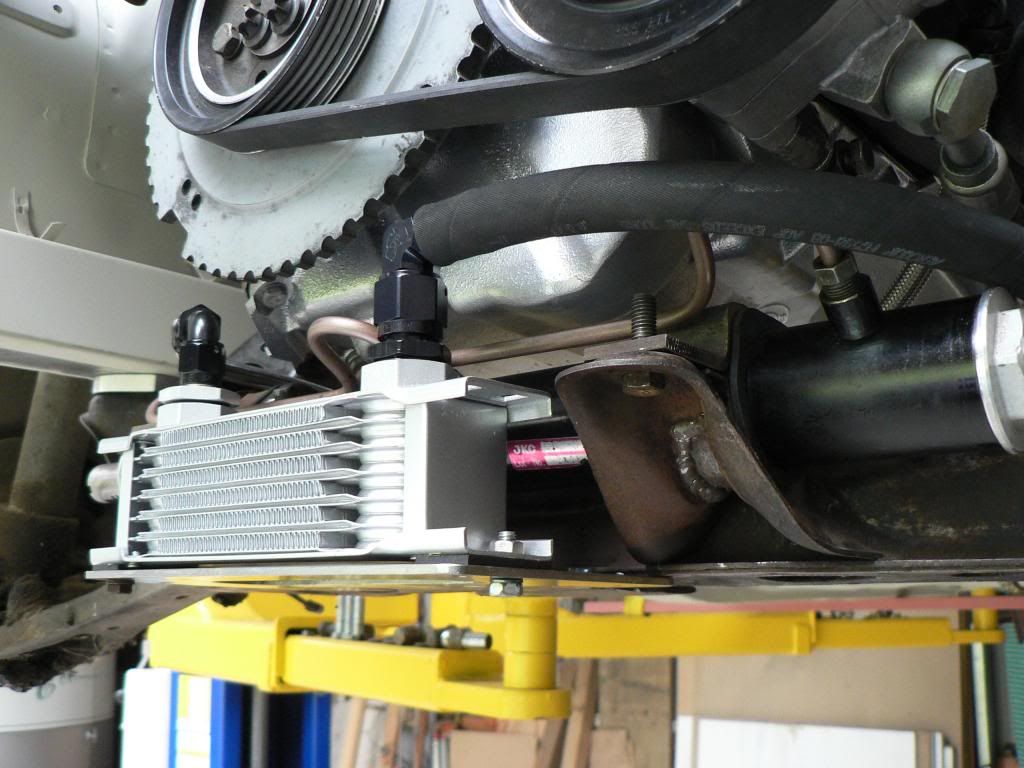
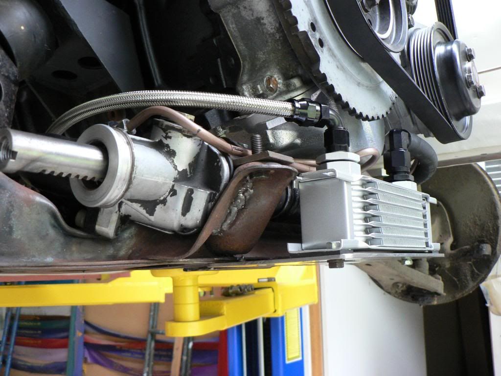
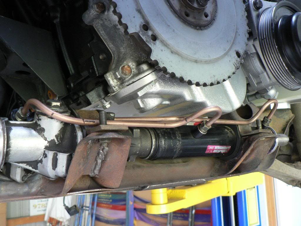
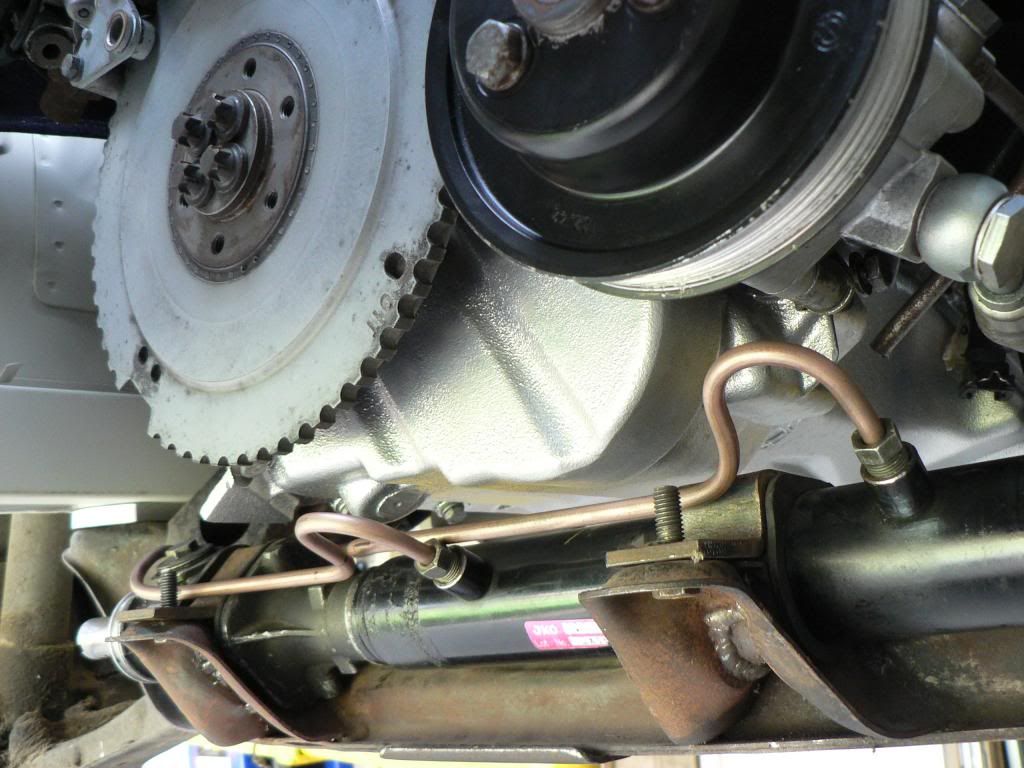
BMW power-steering systems are renowned for overheating if the cars are tracked, most punters install a proper power-steering cooler in place of the typical loop of pipe (like most cars) that normally serves as the cooler. Under-driven pulleys are also an option but don't really fix the issue. Either way I couldn't use the original BMW loop of pipe due to a lack of space so a proper (albeit small) cooler was going to be needed. The original BMW loop cooler sits in front of the rack on the cross member and this logically is the best place for a proper cooler.
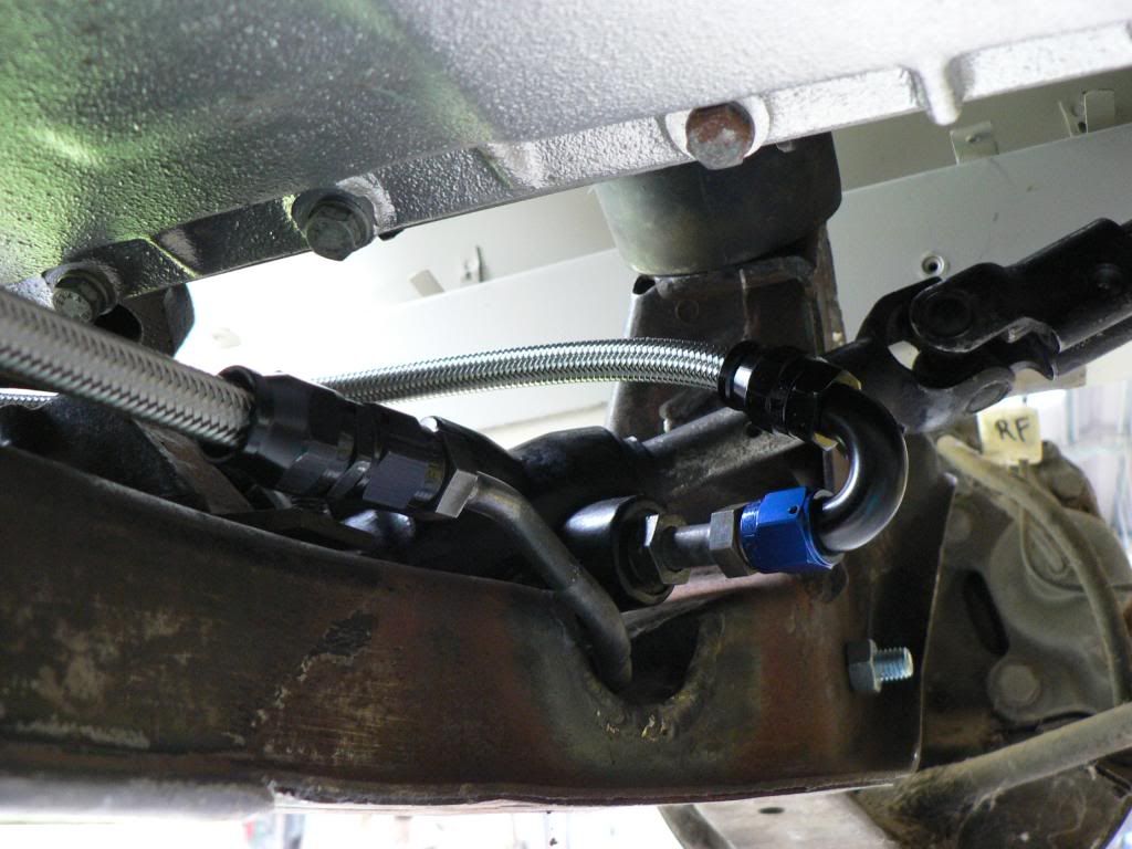
I fabricated a bracket from 3mm plate that is welded to the lower front edge of the cross member and the cooler sits on top of that using rubber isolators top and bottom of the mounts. In the photos the bracket is just tacked for now and I need to get some nice stainless domed Allen head bolts and nylocks to finish it off.The cooler is the largest I could practically fit in the available space....Harmonic Balancer sits very close at the top of the inlet and outlet hoses which required the cooler to be offset slightly for clearance. Lines are braided teflon -6 from the pump to rack and then to the the cooler with a -8 hose tail and rubber hose back to the reservoir.
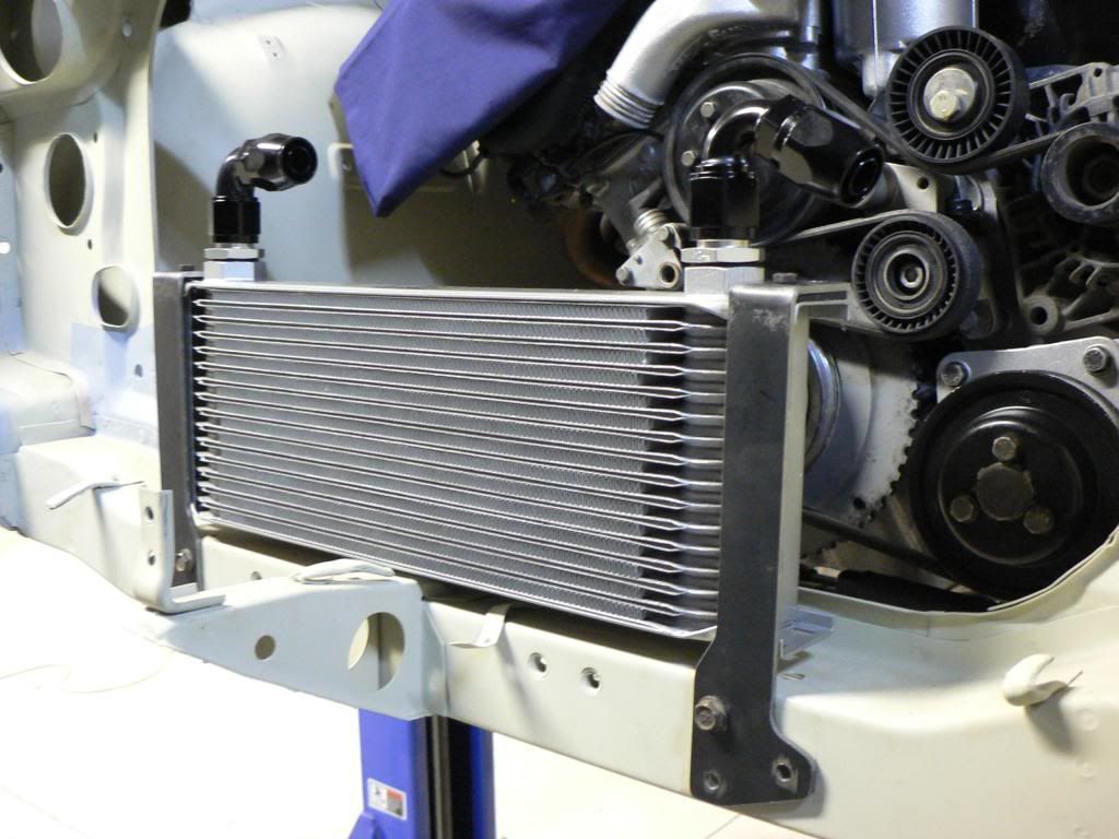
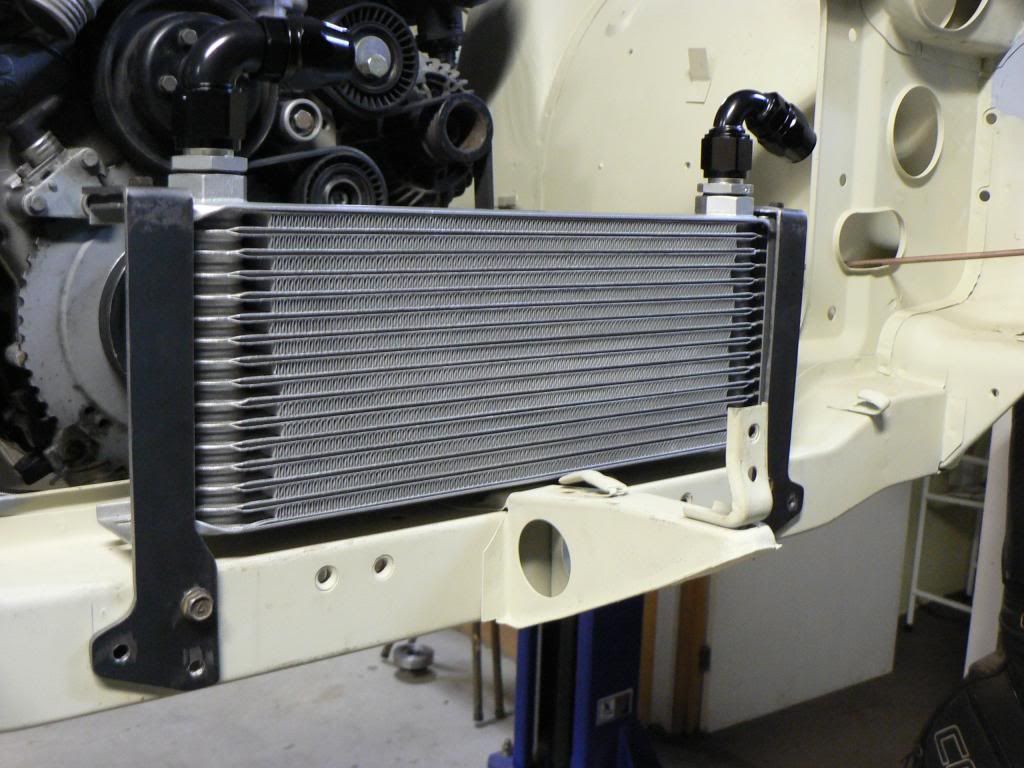
M3's come standard with a pretty substantial engine oil cooler and there is a thermostat built into the oil filter housing where the cooler lines originate. The M3 oil filter housings and coolers are a popular add on for anyone modifying a lower spec M50/S50 series engine as they are a bolt on. The original M3 cooler is the same width as the radiator which it sits under but its only about 70mm high so its wide but narrow and again I couldn't use it as the front of the Z is just too small.
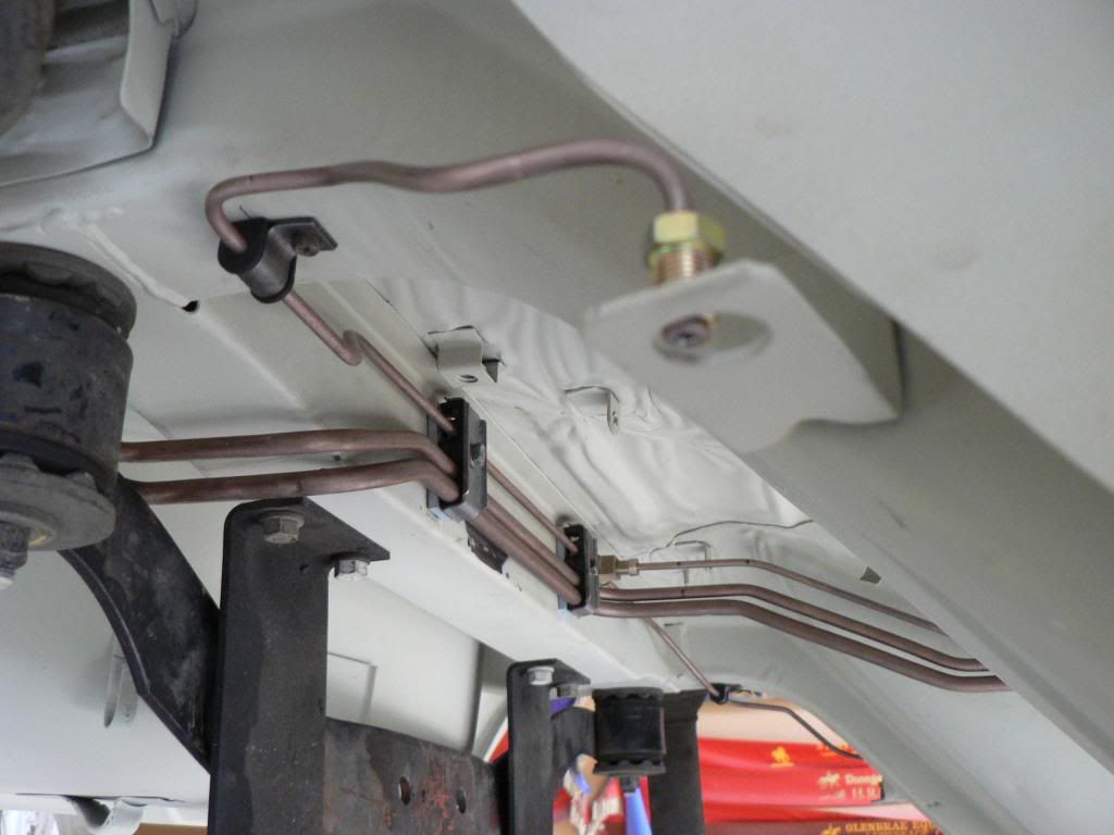
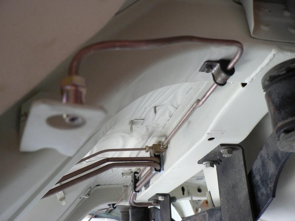
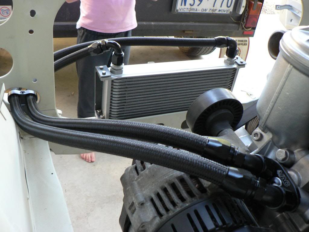
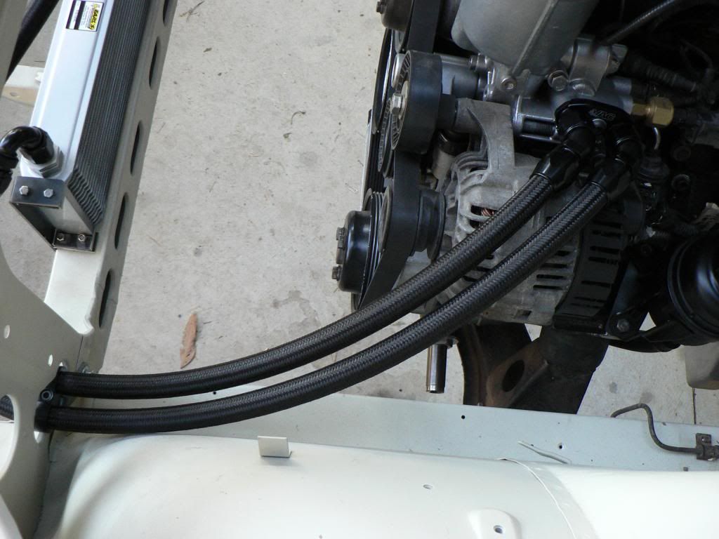
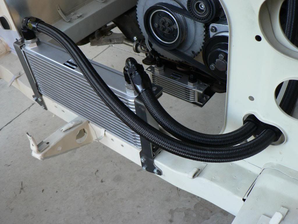
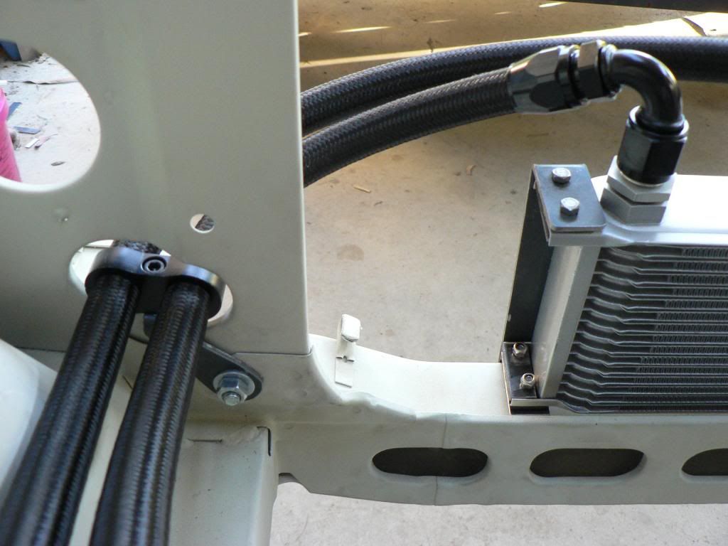
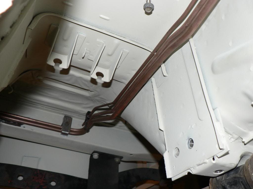
In front of the radiator was the only option for me. There are three holes arranged in a triangular pattern on the front of the radiator support cross-member which lined up well with the Earls cooler I had chosen so like the PS cooler I used some 3mm plate to fabricate brackets and made the same rubber insulators as the PS cooler. Still need to add a lower bracket and the -10 hoses.Plumbing at the back of the car is nearly finished....new brake lines on both sides and new T piece from the front line.
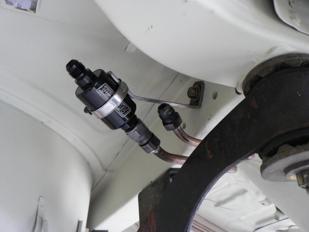
I'm using a Russell inline fuel filter where the braided line from the tank meets the hard line going forward. The filter is small and light weight but I didn't want to leave it just hanging off the hardline so I made a bracket to support it. The clamp will be insulated with some 3mm nitrile rubber to protect the filter. Second hard line is the return from the pressure reg and will connect with braided line to the tank.Time to run the engine oil cooler lines....
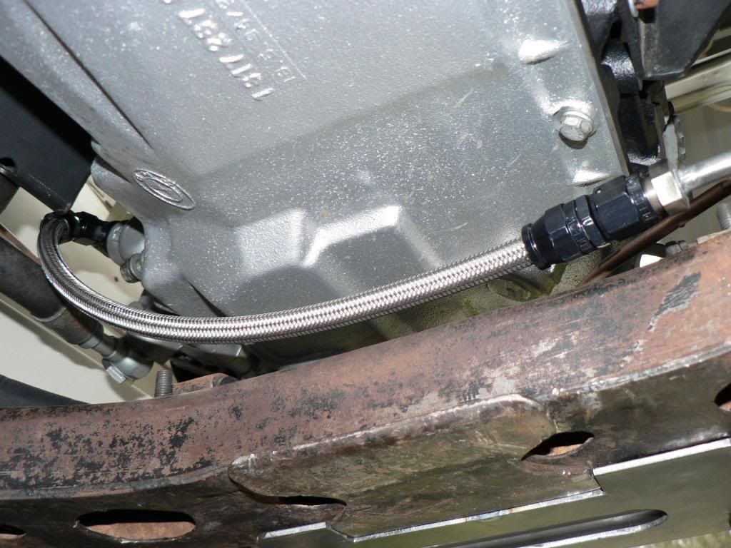
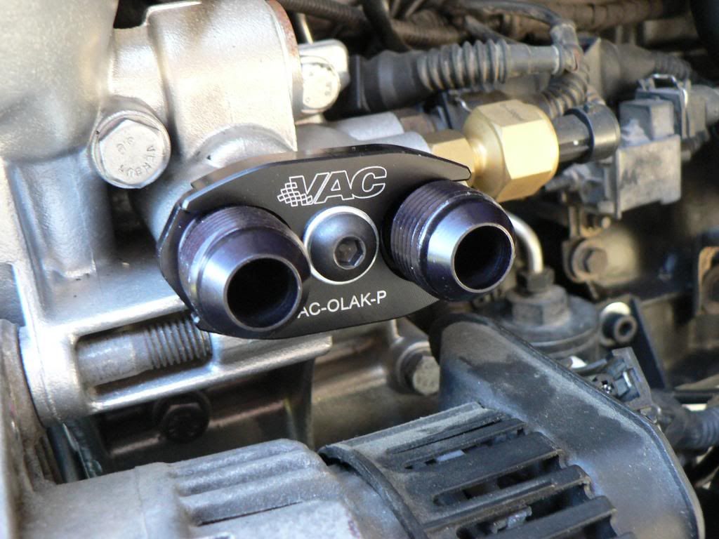
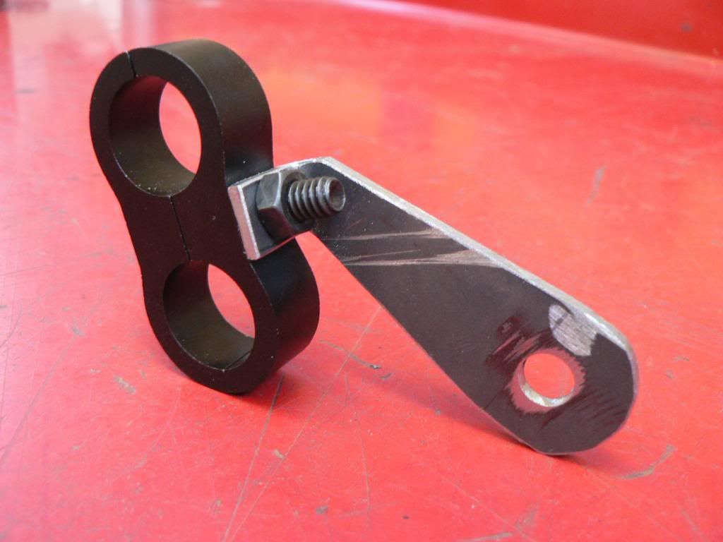
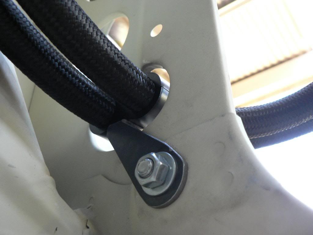
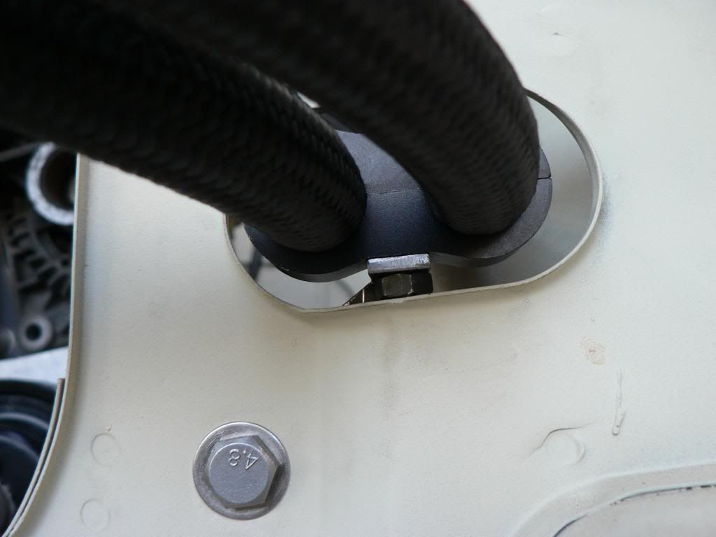
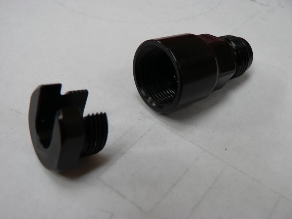
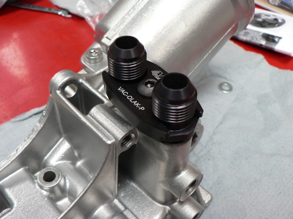
The factory oil cooler lines use a unique O ring set up which cant easily be modified, plus the factory cooler and lines wont fit anyway so Ive used an adapter made by VAC Motorsport that allows -10 AN lines to be plumbed from the factory oil filter housing.Getting the cooler lines through the radiator support was a bit of a mission. Had to keep the lines from rubbing on the inner guard, rad support and have the right angle for them to join the cooler so I made a bracket which bolts to the lower radiator attachment hole and used an overly expensive "billet" double hose clamp (which worked perfectly).
-
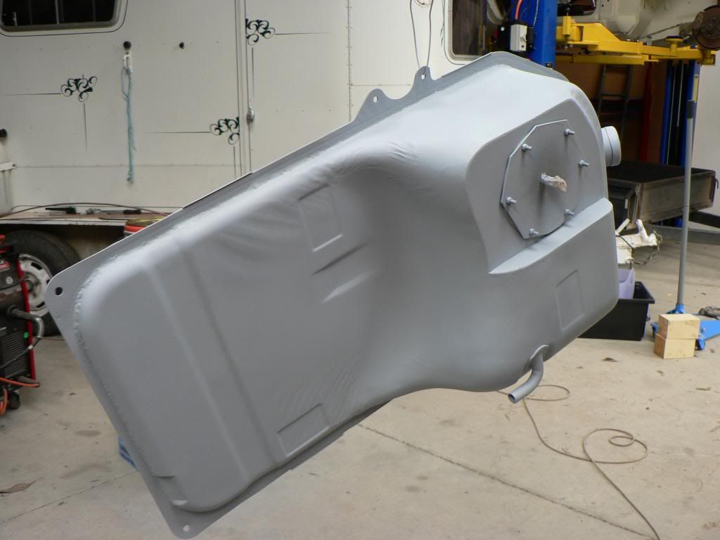
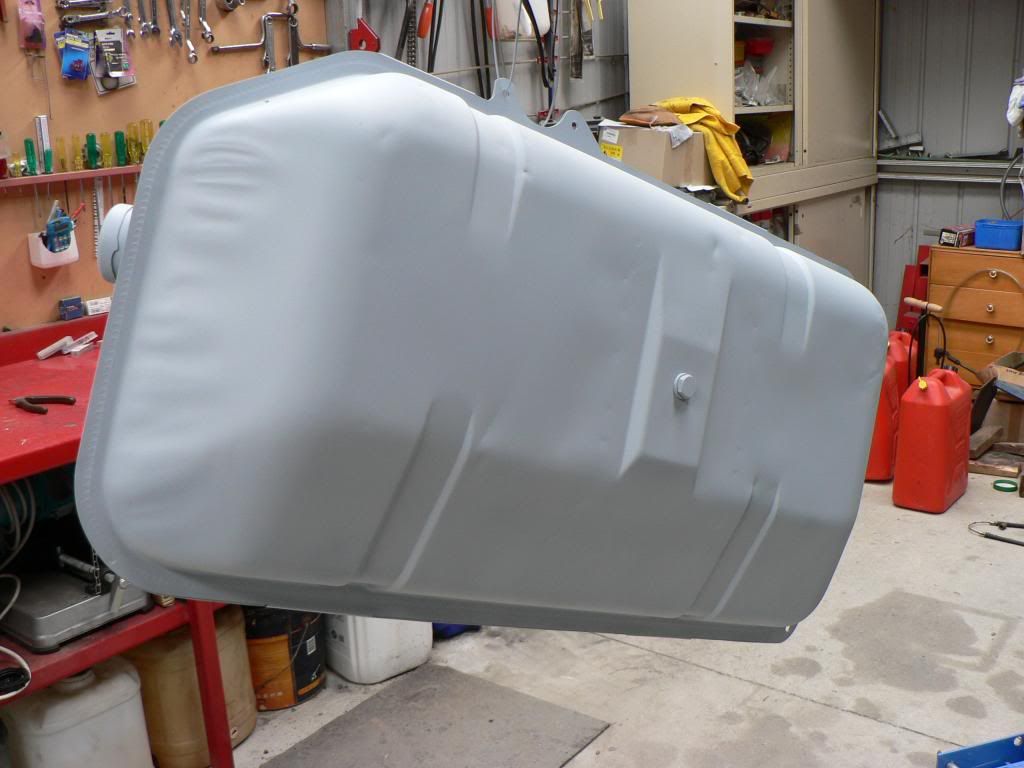
So, took my fuel tank to Melwide Radiators as there was plenty of rust and scale inside after sitting with no fuel in it for nearly 20 years also had a decent dent in the bottom and I needed the original fuel sender and pipes covered over.
They quoted $400 to cut the tank in half, media blast inside and out, tin the whole of the inside so it wont rust again, weld it all back together weld in the plate for the fuel module and cover over the original sender and pipe holes.
They cut the tank on the top side of the original flange where the factory joins the two halves so the welds aren't seen from underneath the car. In the first photo below you can see the welds, not the greatest looking but he pressure tests and guarantees no leaks. He did a good job on the lead filling and covering of the original sender and pipes.
Reasonably happy with the outcome given the hours they put in, only thing I would do differently is pick it up as soon as its finished because in the week I left it sitting there the acid they use to tin the inside had put surface rust on all of the media blasted outside! Managed to get it inside my blasting cabinet and give it a clean up then gave it a coat of etch primer straight away.
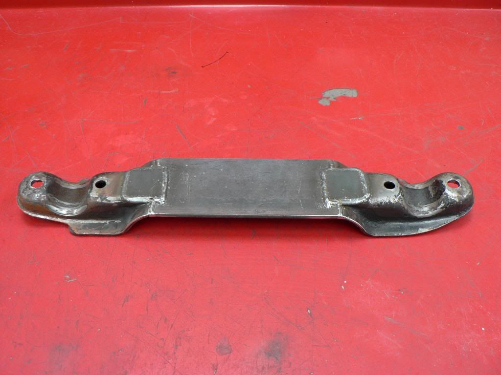
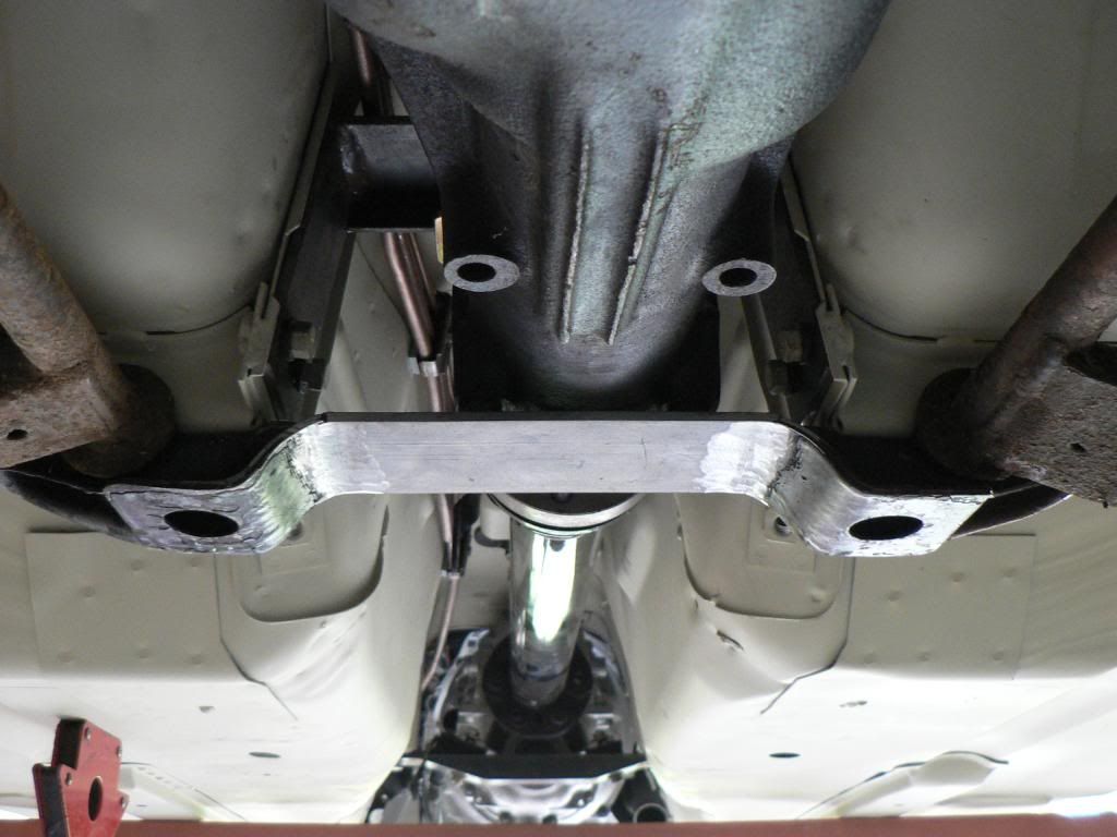
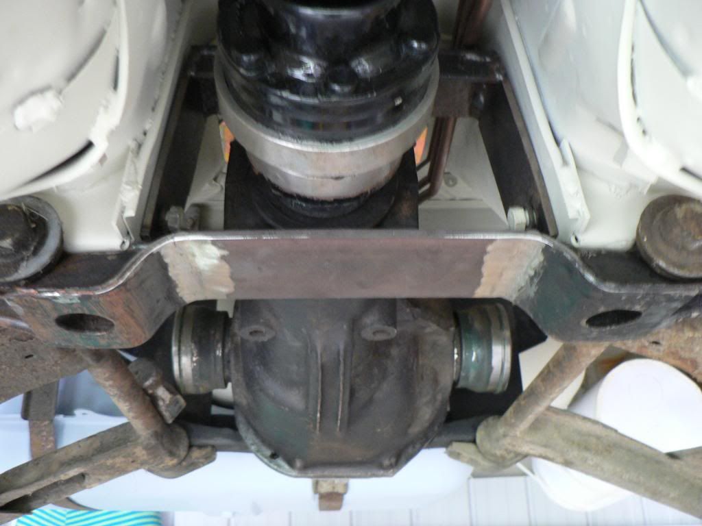
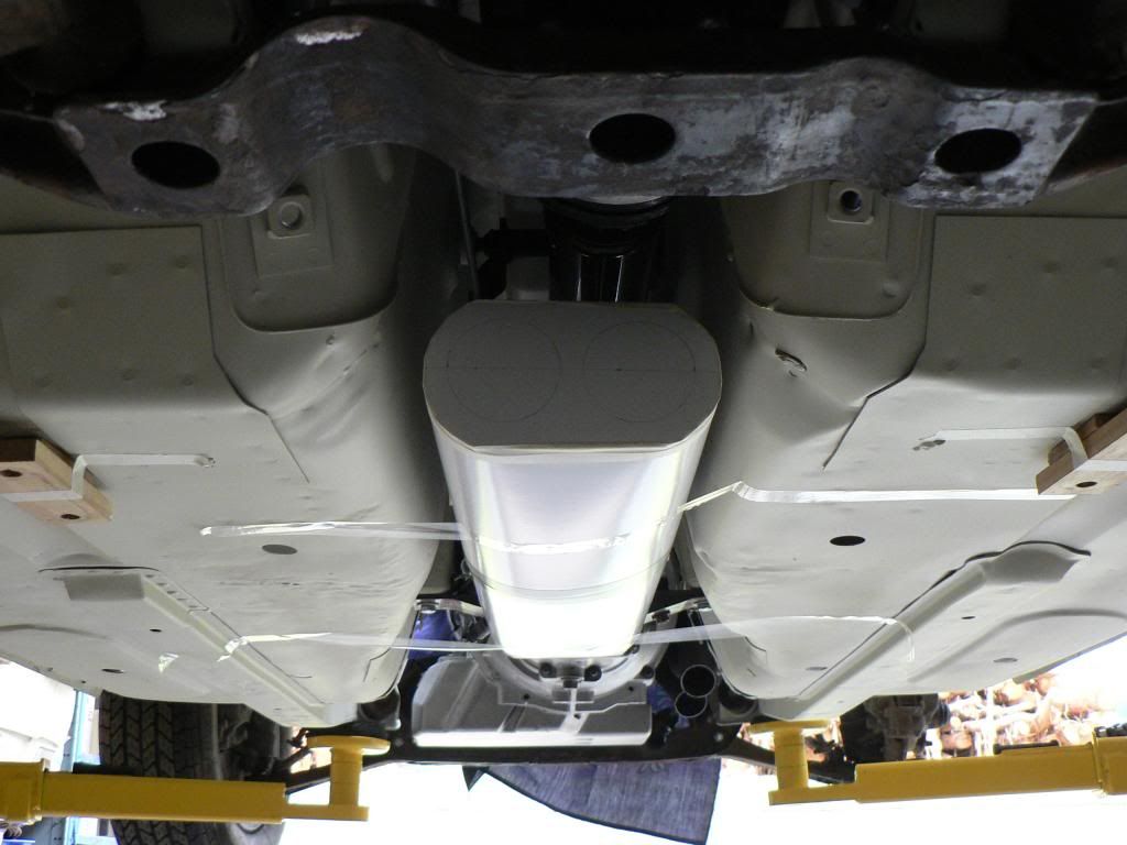
Couple of little dings that will get a wipe of bog before it gets properly painted.So I need to get some clearance for my dual exhaust where it goes under the diff crossmember.....
1. Take two perfectly good crossmembers.
2. Attack with cut off saw.
3. Weld in 5mm plate and brace on back side.
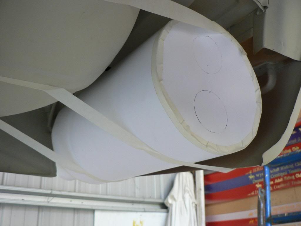
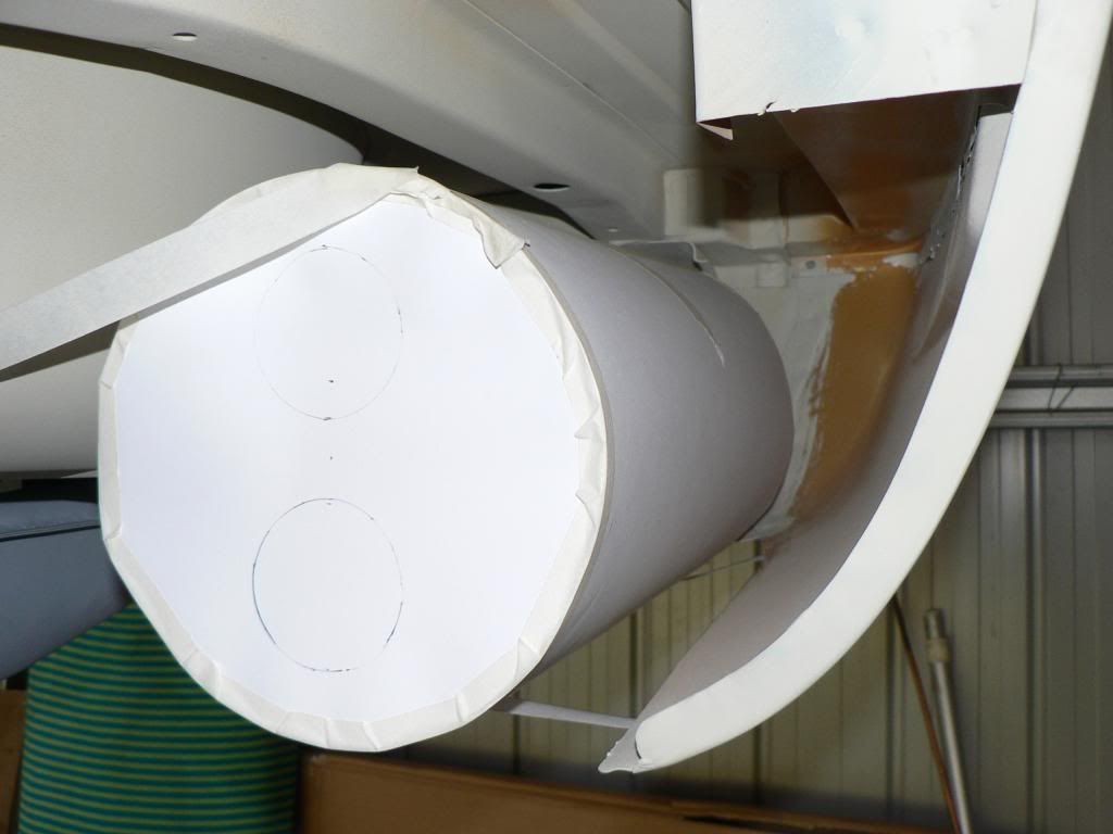
4. Hey presto plenty of exhaust room.Ive mocked up a couple of versions of the rear muffler as I just cant bring myself to like the stacked twin pipes ala 432 style. After speaking with Mick from Devonport I'm going to go with a muffler the same size as the Reinhard rear muffler with twin 2 1/4 inlet and the pipes merging inside to a single 3" outlet with a down-turned tip.
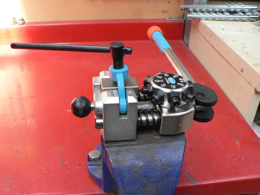
Given the amount of brake, fuel and oil lines I need to run I lashed out and bought an Eastwood flaring tool. A very nice piece of kit and brilliant to use.
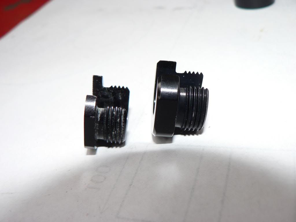
Because I have rotated the control valve on the top of the WRX steering rack 180 degrees I had to make new hardlines to the cylinder. I wish bending was as easy as flaring!A box of stuff arrived from Summit which included my Russell EFI adapters http://www.russellperformance.com/mc/adapt_fit/fuel-efi.shtml . After reading a few comments about the ones without the screw on end caps coming off I thought this the safer way.
One problem I didn't anticipate when trying to fit them to the BA/BF Falcon fuel module was the lack of space between where the tube comes up out of the module and does a 90 degree turn and the collar which the adapter end cap screws down on to. The "head" of the screw on end caps is 5mm thick which is plenty so I took 2mm thickness off this and it gave enough room to fit the end cap over the tube.
Had to do this on two of the tubes, middle one was OK so all good now. -
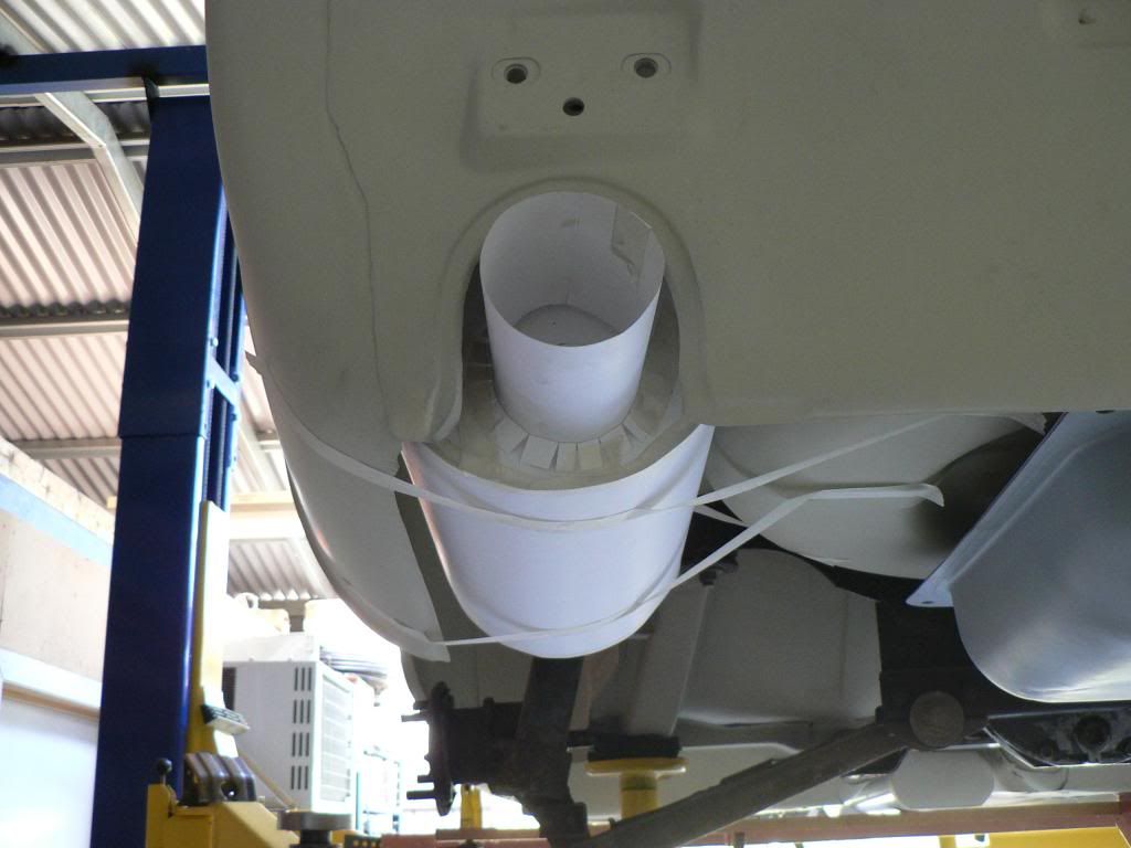
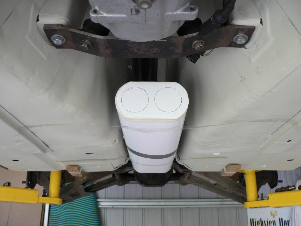
Ive done a fair bit of research on the BMW forums and its pretty clear that dual pipes front to back are the way to go to retain the unique exhaust note that the M3 engines have. A large single system would be cheaper, lighter and probably make the same power but they sound pox and drone badly.....so say the forums...and its telling that all the aftermarket systems are dual pipes.
As the car needs to be engineered it also needs to meet noise limits ...96DB I think is the number so making an exhaust that is legal and sounds good is going to be a challenge. I'm going to need to maximize the size and volume of the resonator and rear muffler as I want to stick with straight through design if possible. I made a cardboard mock up of the resonator to confirm the maximum size that will fit in the tunnel and maintain the best ground clearance. I'm going to use 2.25 inch stainless for the pipes. I'm comfortable with making the exhaust system but would prefer to have someone else make the resonator and rear muffler if possible, I reckon I could make my own but the time it would take is the killer.On to the topic of fuel and brake hardlines. A pet peeve of mine is cars that people have put huge amounts of time and money into and their fuel system looks like a last minute and poorly executed add on, dogy P clamps self tapered into the floor and cable ties don't cut it for me. It can be difficult to get an outcome that looks good and is properly safe.
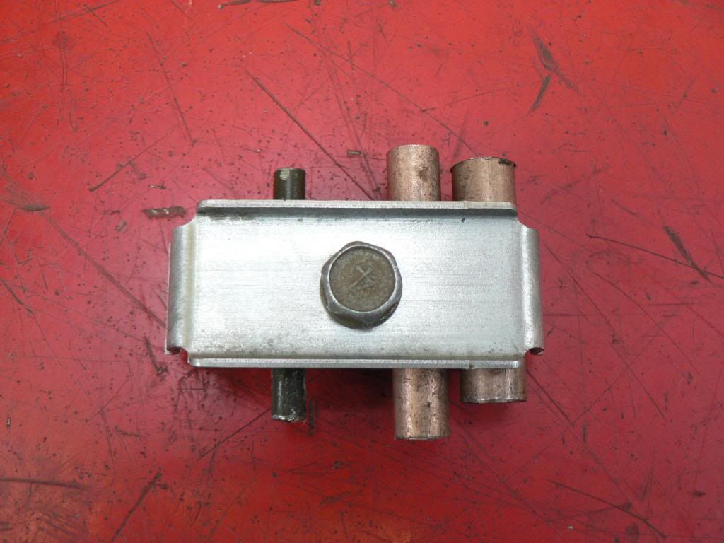
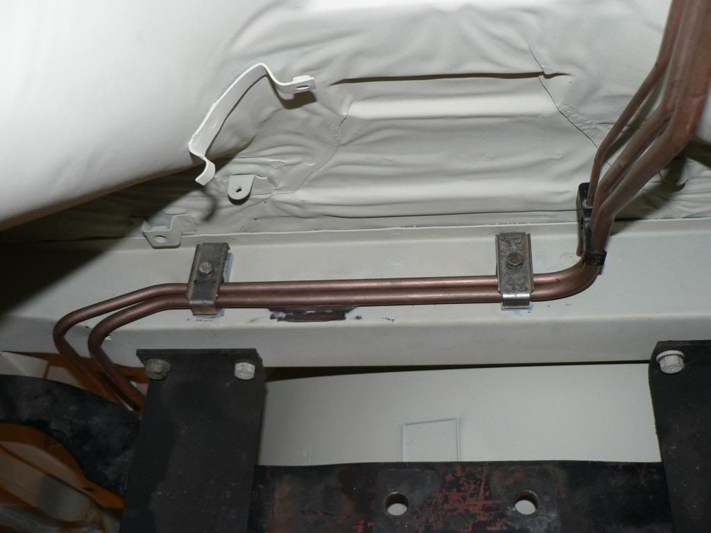
Because the BMW engine is offset to the drivers side I have no room in the tunnel where the fuel and brake lines ran originally and also the exhaust is on the wrong side so I have to move them to the other side. I also need to run bigger fuel 3/8 supply line and 5/16 return lines.
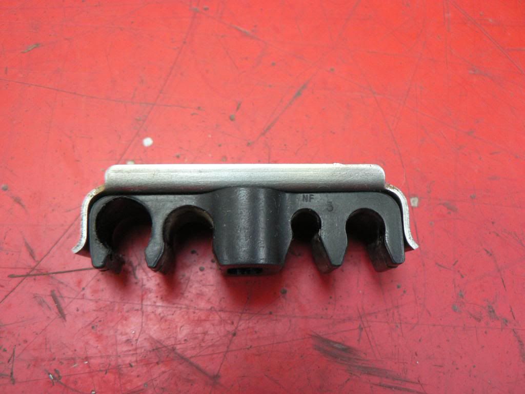
I want to use factory type pipe clips but I also don't want to drill holes and have bolt heads or rivets etc in the side of the tunnel either so I went to pick a part and spent ages crawling under cars in the mud looking for something that will work. Ended up with clips from a mid 90's Pajero, it has four slots but I only need three, two for fuel and one for brake. On one side it has 2 x 5/16 slots and the other has a brake pipe slot and one other, using a drill it it was pretty easy to enlarge the outer 5/16 slot to 3/8 and they all clip in really well and are well retained.
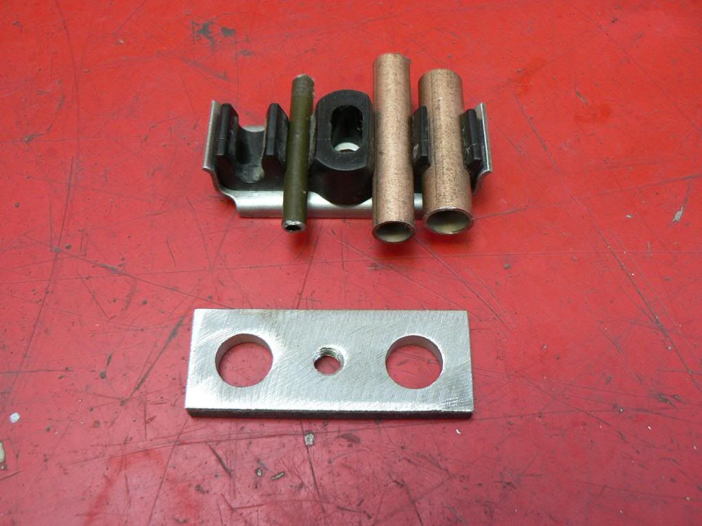
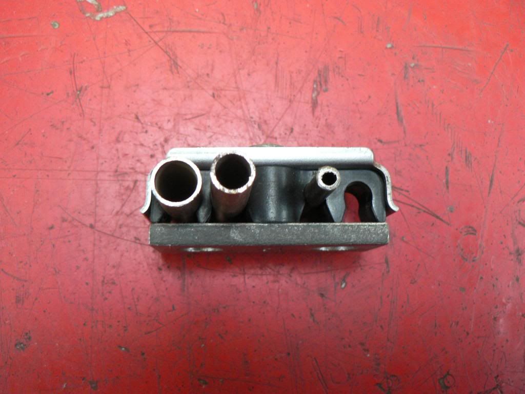
I made a base from 5mm x 20mm strap, drilled and taped the center hole for the M6 bolt and then drilled two larger holes which will be used to place a small weld to attach the base to the tunnel, this way you will see no welds once the clip is bolted down.
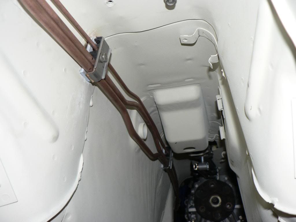
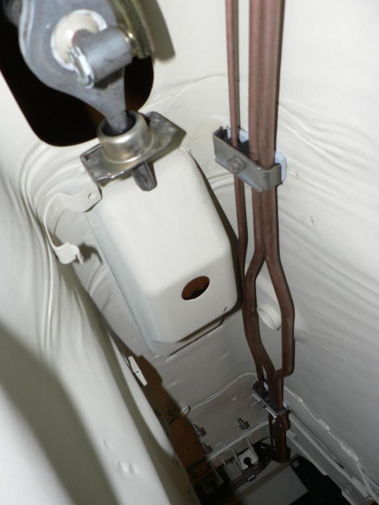
Ive got my bundy tube and bender so that's next.Pipework in the tunnel is done. 3/8 fuel supply on the bottom, 5/16 fuel return in the middle and 3/16 rear brake line on the top. Took some time to get it looking straight and very happy with the clips/brackets which worked perfectly. 3/8 required a good quality bender which my brother already had. 5/16 was easier and an elcheapo bender did the job, the 3/16 just needs fingers!
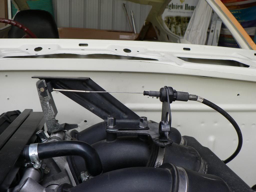
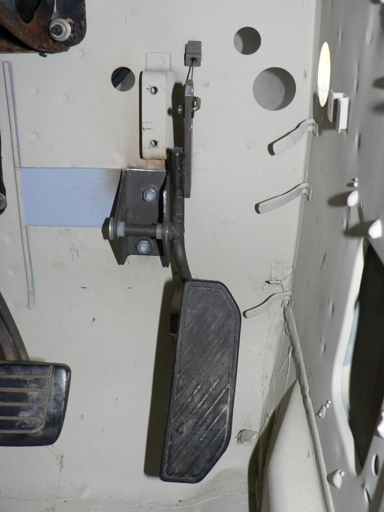
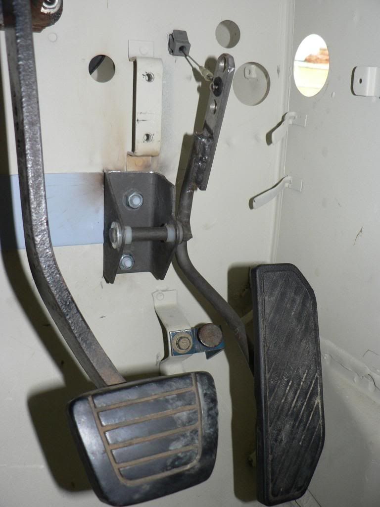
Its only steel bundy tube but Ive seen a picture on another forum where the guy has had his lines powder coated black...looks grouse against the body colour underneath the car so I'm going that way.Got the accelerator pedal finished today. Couldn't believe how long it took ......... the BMW cable enters the firewall on an angle so took some time and lots of measuring to ensure the hole in the firewall was in the right place and that the pedal was in the right place. Used an ED Falcoon accelerator pedal with the top cut off and adapted to suit the BMW cable end, added some additional holes so I can fine tune the feel and travel but don't think I will need to as I replicated the BMW pedal ratios and it feels spot on. I had to add some additional reinforcement as the whole firewall was flexing way to much. I need to get a new cable though as the one that came with the engine was just ripped out and they damaged the outer...$65 for a genuine cable incl freight from Schmiedmann in Europe so not too scary.
Sat in the car and changed gears and made brrrm brrm noises as I pushed the new third pedal for a few minutes just to keep the motivation up! -
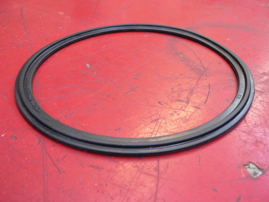
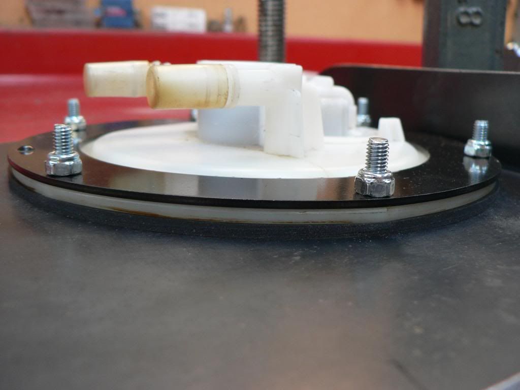
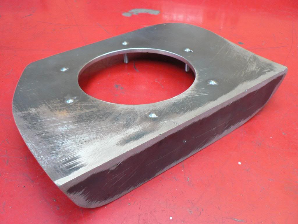
The module has a steel reinforcing ring that sits over the top to spread the load when you tighten it down and in the original Ford installation the seal has a ridge which fits into a grove in the tank to ensure sealing, I couldn't replicate this so I bought some 3mm Nitrile rubber from Purple Pig and fabricated my own but it does rely totally on the steel reinforcing ring to spread the load for a good seal....we shall see... I may have to make a stronger reinforcing ring as I fear it wont provide the even tension on the seal.
The tank has a good dent in the bottom side which I need to fix and in addition I need to close over the original sender hole and pick up pipe so Ive decided to farm this out to "experts", Mossy has recommended http://www.melwideautoradiators.com.au/radiators-aircon-heaters-fuel-tanks/fuel-tank-repair/ for this so I'm going to take the tank to them and see what they say.
-
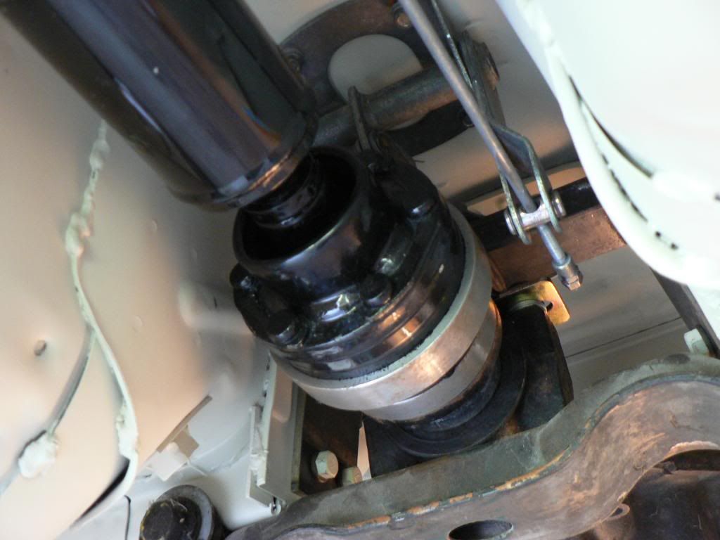
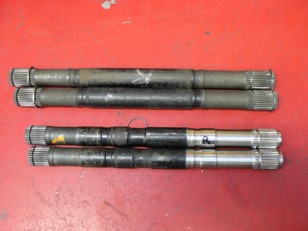
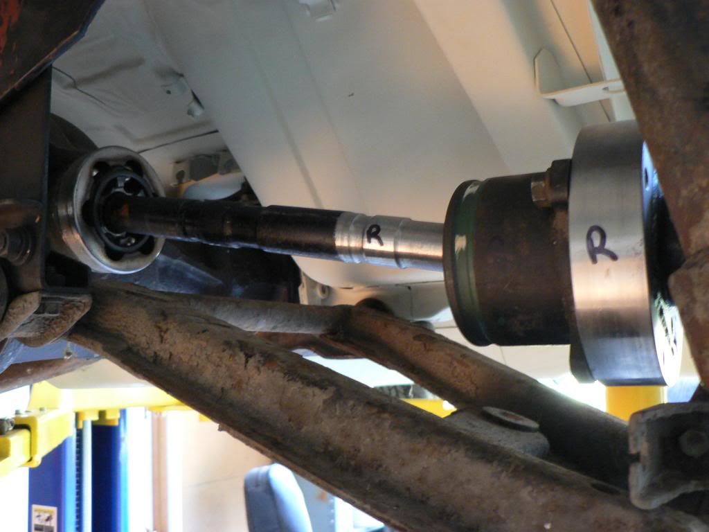
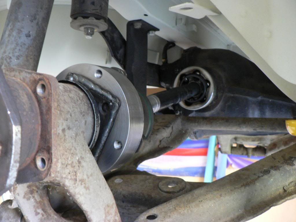
Well, happy to report I now have a complete driveline from engine to wheels, meaning my tailshaft and CV shafts are done.
Tailshaft was shortened by Knox Driveshafts. Jeff, works from his backyard, very reasonably priced, knowledgeable and used to rally Z's many years ago. Tailshaft uses the standard rubber BMW guibo joint at the front and the BMW CV joint at the rear using an adapter to mate with the R200 pinion flange.I'm keen to make the driveline as bullet proof as possible so I wanted to go with CV's for the driveshafts.
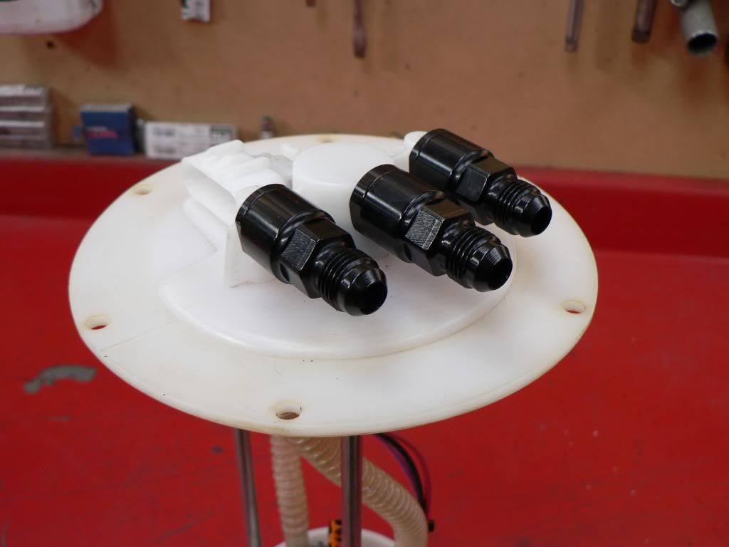
After reading about people having issues with the Z31 turbo shafts being a smidge too long and causing handling issues and damage I mocked mine up in the car and found I only had 2 - 3 mm of clearance which wasn't enough in my book. I considered Wolf Creek but didn't like some of the reports and wasn't prepared to pay for the SW Motorsport version so when a member here advertised some R32 Skyline shafts that had been shortened and resplined I took the plunge. They aren't perfect and took some time to find circlips that will hopefully do the job but they are 35mm shorter than the standard Z31 turbo shafts and then I had Rob Crichton http://www.viczcar.com/forum/index.php/topic,1861.0.html make up some 25mm wide adapters. I now have a minimum of 10-12mm of clearance at all suspension travel points. Grease and new boots and they ready to rock.I'm taking no credit for the fuel system here, this was all Mike's (NZeder) doing, Ive just copied his great ideas! Thanks again Mike.
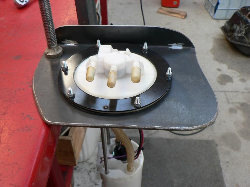
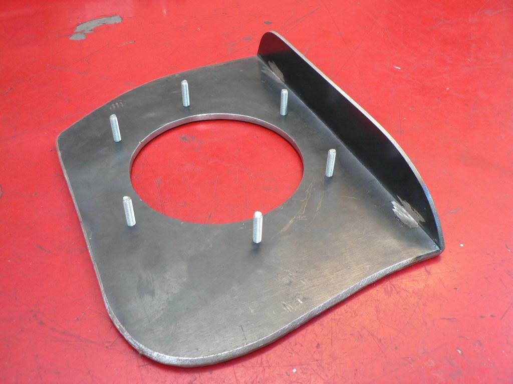
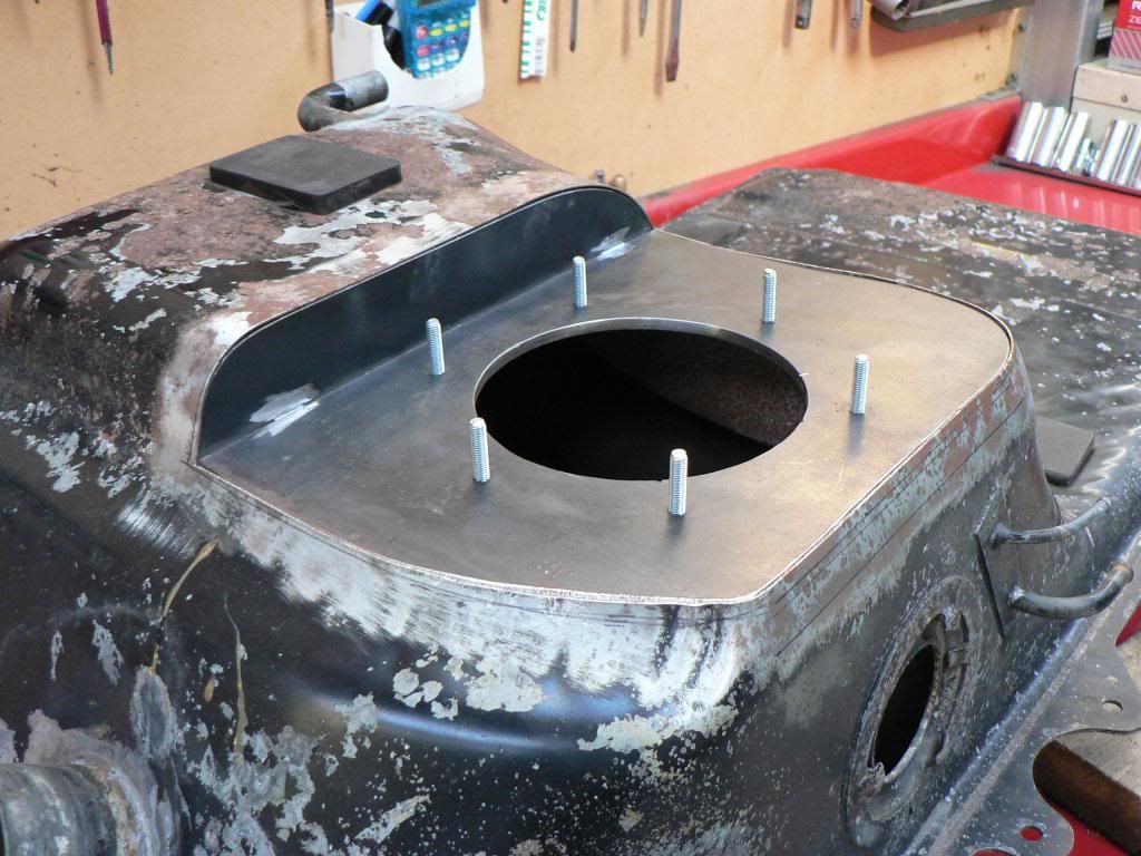
I'm (we) are using a BA/BF Falcon wagon fuel module which incorporates the fuel pump, swirl pot and fuel level sender all in one unit and will hopefully provide quiet and reliable fuel delivery without the noise and fuel smells associated with some external installations. I have already installed a high volume/pressure Walbro in this module earlier in my thread.
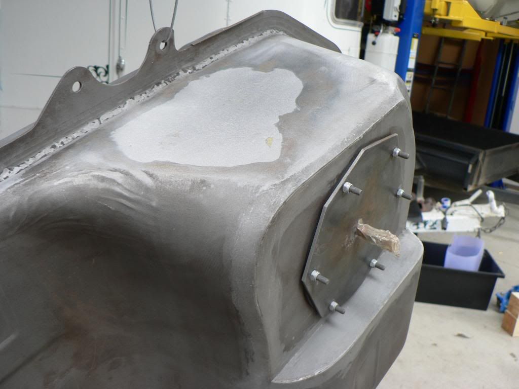
First off you need to give the top of the tank a bit of a haircut and then fabricate a flat section that will be welded in to mount the module on. I ended up using 5mm plate for the horizontal piece and 3mm for the small vertical piece, 5mm is overkill but I wanted to ensure that the module sealed well and 3mm may have distorted when the module was tightened down or when it was welded into place on the tank. Stud holes were drilled and tapped then a plug weld in the bottom to ensure no leaks. -
Its been a long time since Ive updated this thread. I promised Ron (RTZ) that I would keep this thread up to date and Ive been negligent of this responsibility....so here goes:
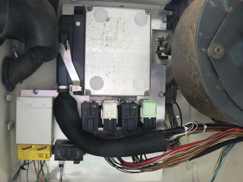
I cut up some 3mm alloy sheet to make a mounting board for the ECU, EWS bits and relays. Used the fan mounting points on the RHS and there is a single 5mm captive nut on the firewall (no idea what its used for) for the other side.
Drilled and tapped two holes to mount the ECU and cut the original plastic relay mounts from the M3 fuse box and riveted that to the plate. The relays now just clip on. Its tight for space and the fuse box and the speed simulator will need to be mounted on the side kick panel.
Still need to make all the connections from the ignition switch and the EWS box to the 12 pin connector but that can wait. -
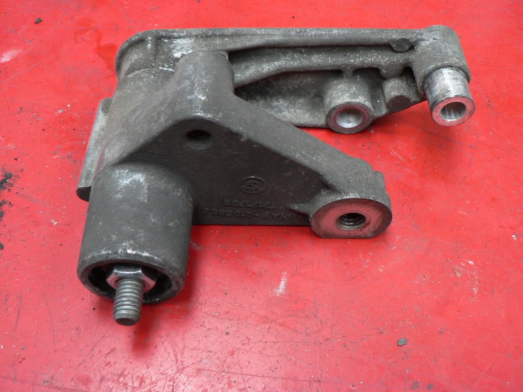
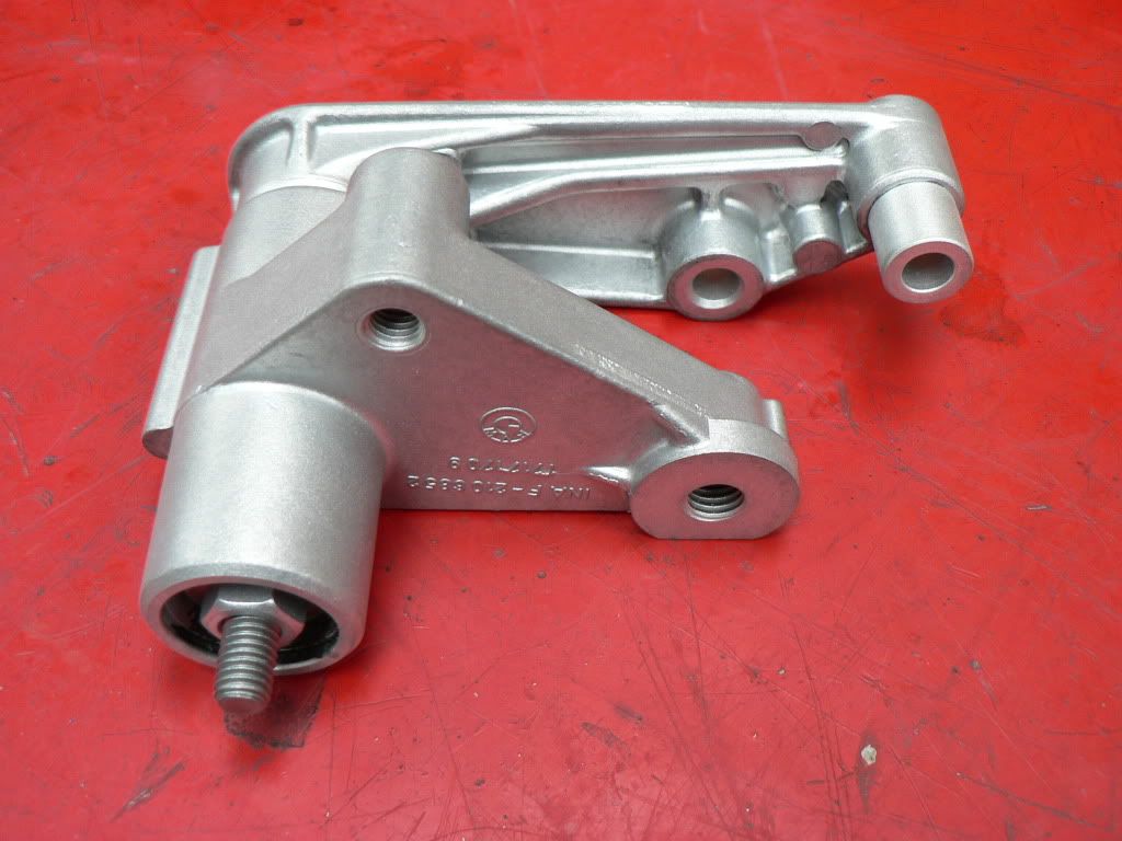
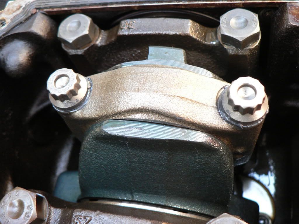
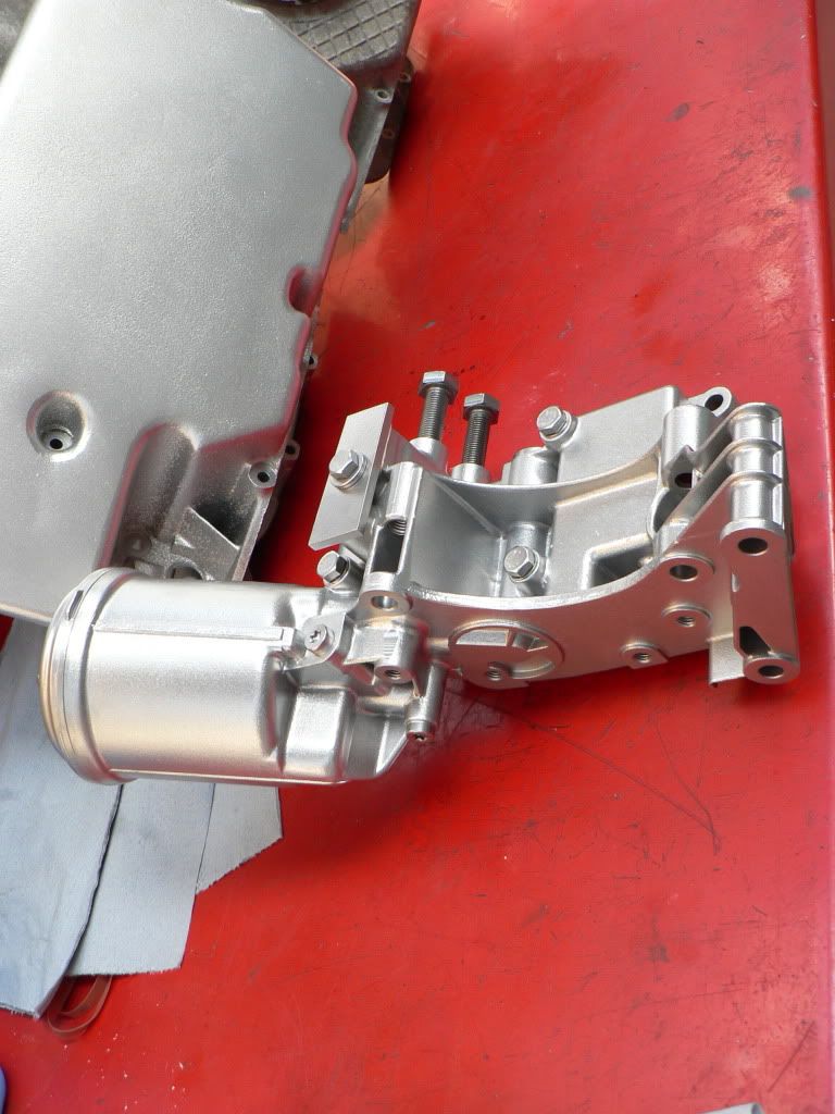
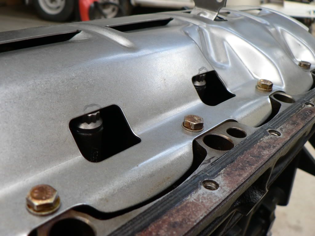
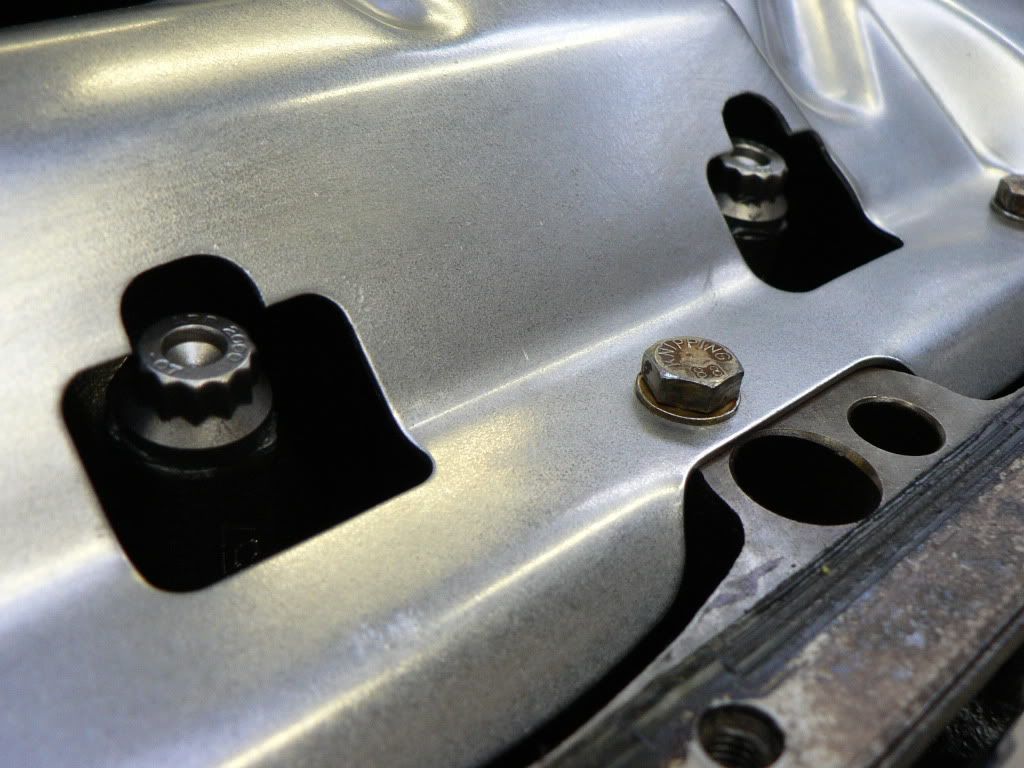
Nice motor mounts
Thought they looked familiar!
-
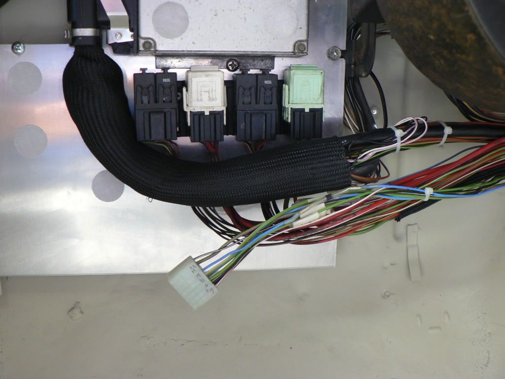
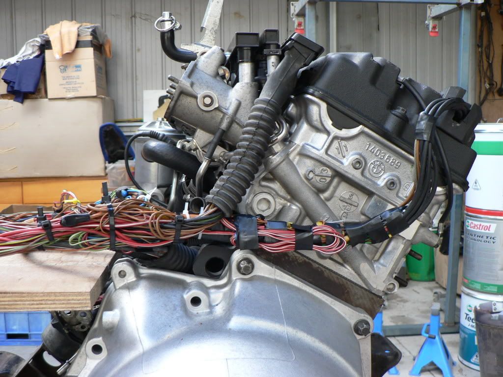
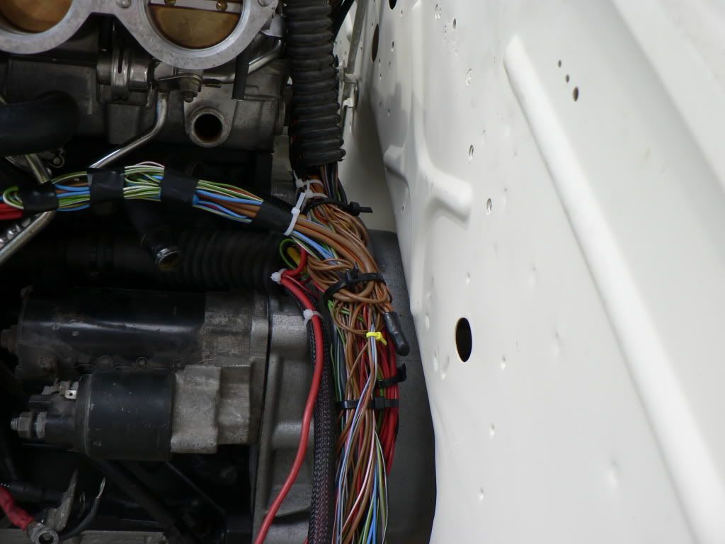
Wiring time!
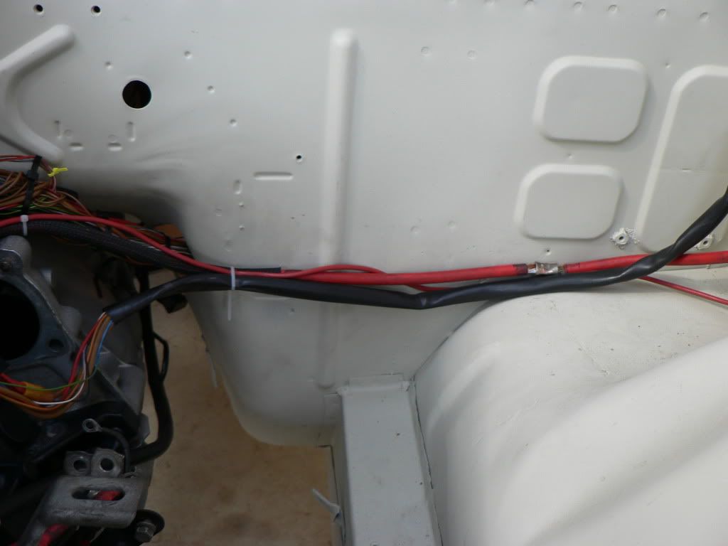
In the last pic above you can see how the standard engine wiring harness is housed in a big ugly plastic box, which in the M3 engine bay hangs from the firewall and sits over the back of the cylinder head. The box doesn't look out of place in the M3 engine bay as there are plenty of other plastic trims and covers but its wrong in the Z bay. I want to keep the engine bay as clean as possible without going to the extent of completely hiding all the wiring, in addition the +ve and -ve cables to the battery are on the wrong side and the other issue is that the plastic box sits right where my bonnet catch bracket is......so time to redo the harness.
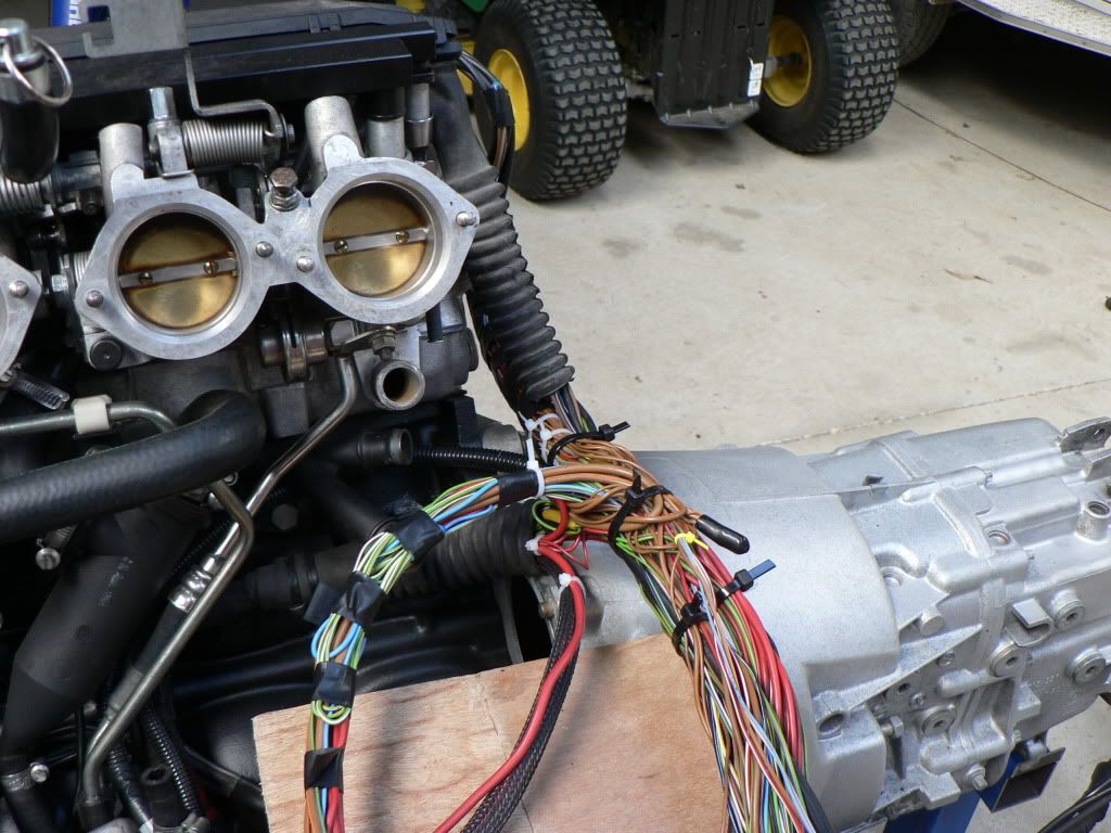
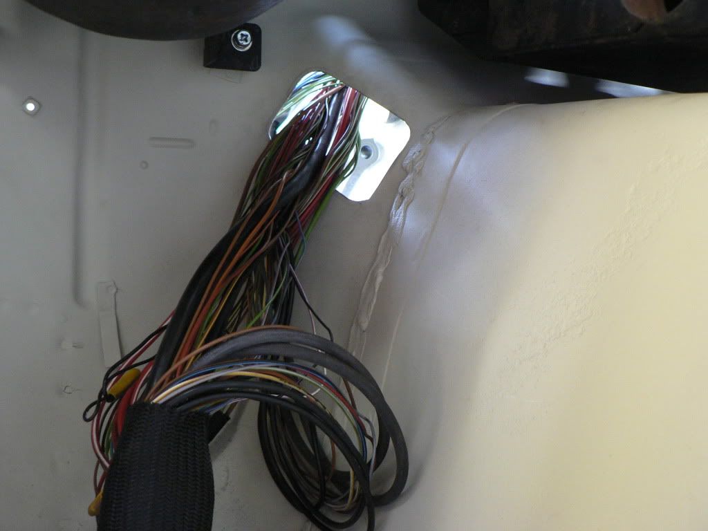
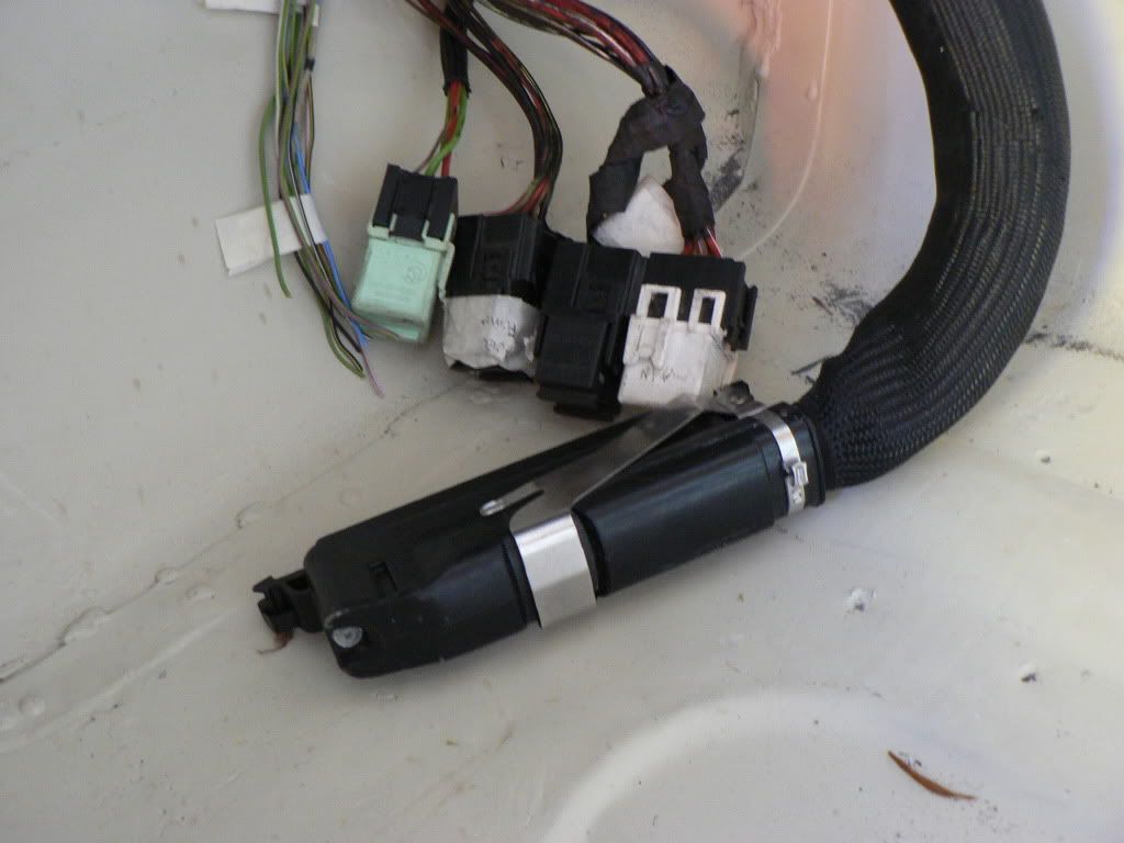
I need to bring the battery cables across to the correct side, route the main harness down and behind the cylinder head so it cant be seen and then bring the main ECU plug, relays and the plug that normally connects the engine harness to the body harness inside the cabin. These also need to be easily unplugged for engine removal.
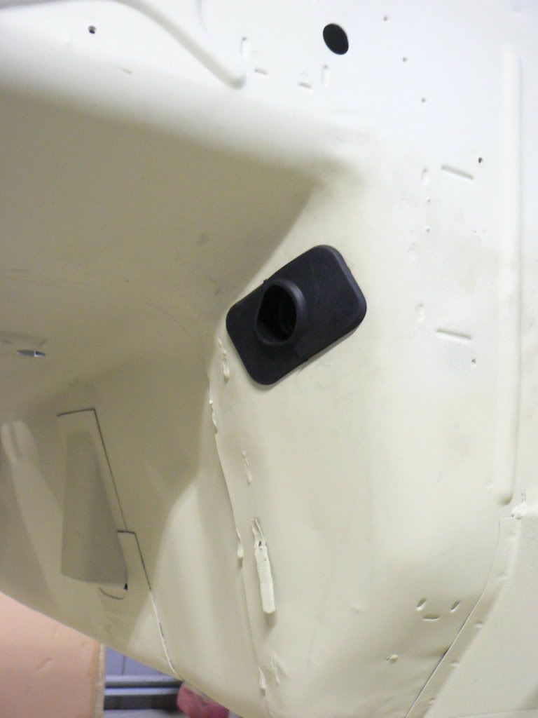
On the M3 the ECU, relays and harness plugs are all in waterproof compartments in the engine bay and understandably so as there is probably 120 wires all up, this results in a very thick harness that I need to bring through a grommet into the cabin and the transmission tunnel is the best place to do it. After lots of research on the interwebs and 3 trips to pick a part I found a good grommet which came from a 2002 BMW 535. The shape and OD is big enough to get the bulky plugs and relays through and the ID is just the right size for the harness.I still need to do a final tidy up of the harness and add some split conduit but it all sits well and will look OK when its all done. Once the airbox is in place the only thing you will see in the engine bay is the battery cables running across to the battery in the approximate position of the last photo.
The next thing will be to mount the ECU, relays and all the EWS security bits on an aluminium panel above the passenger foot well.
-
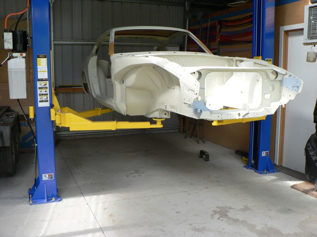
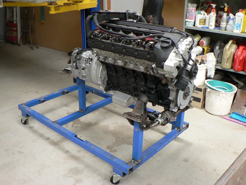
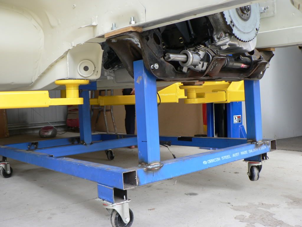
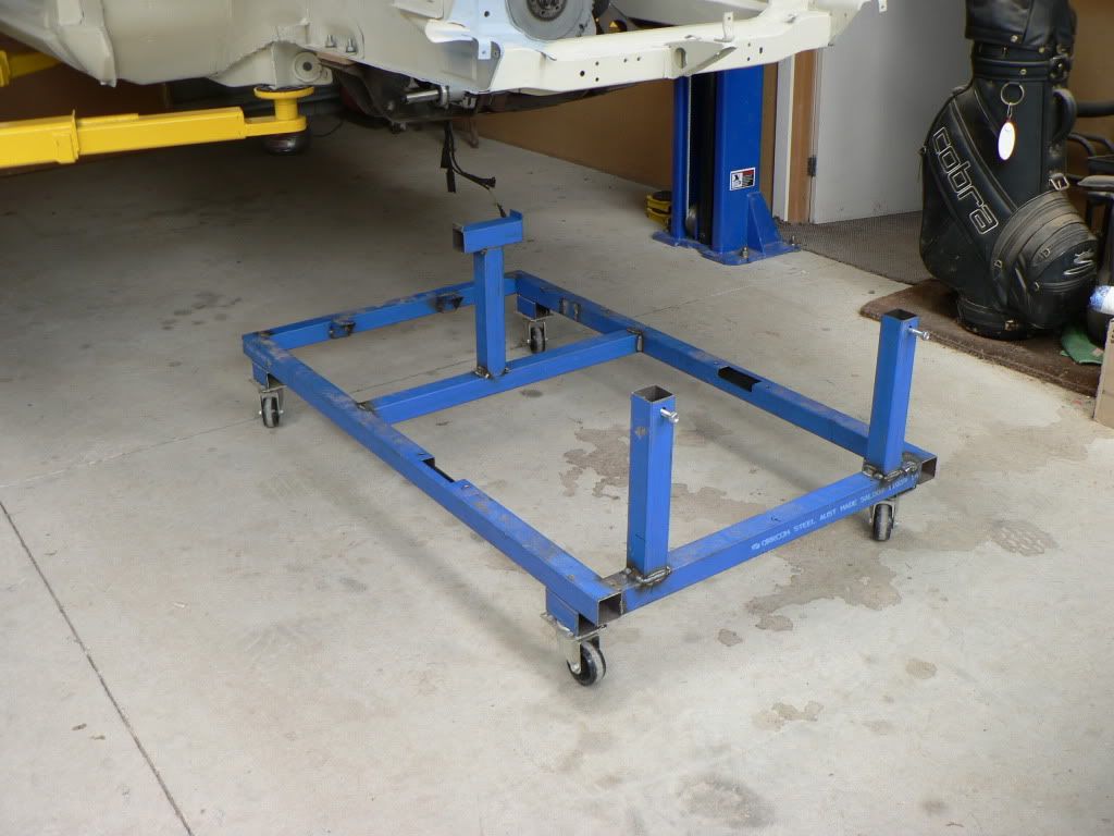
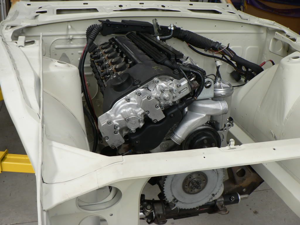
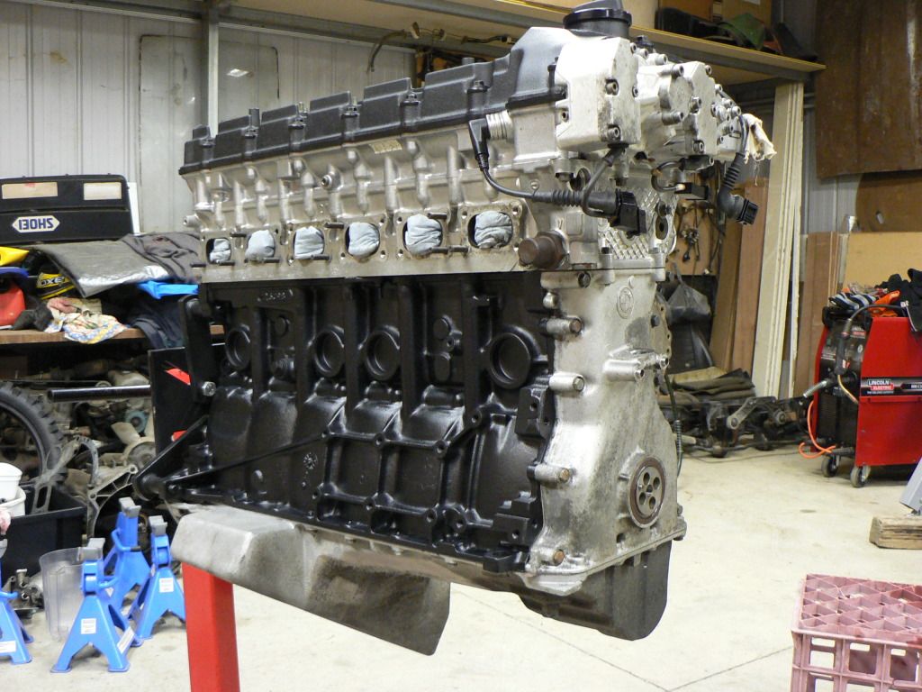
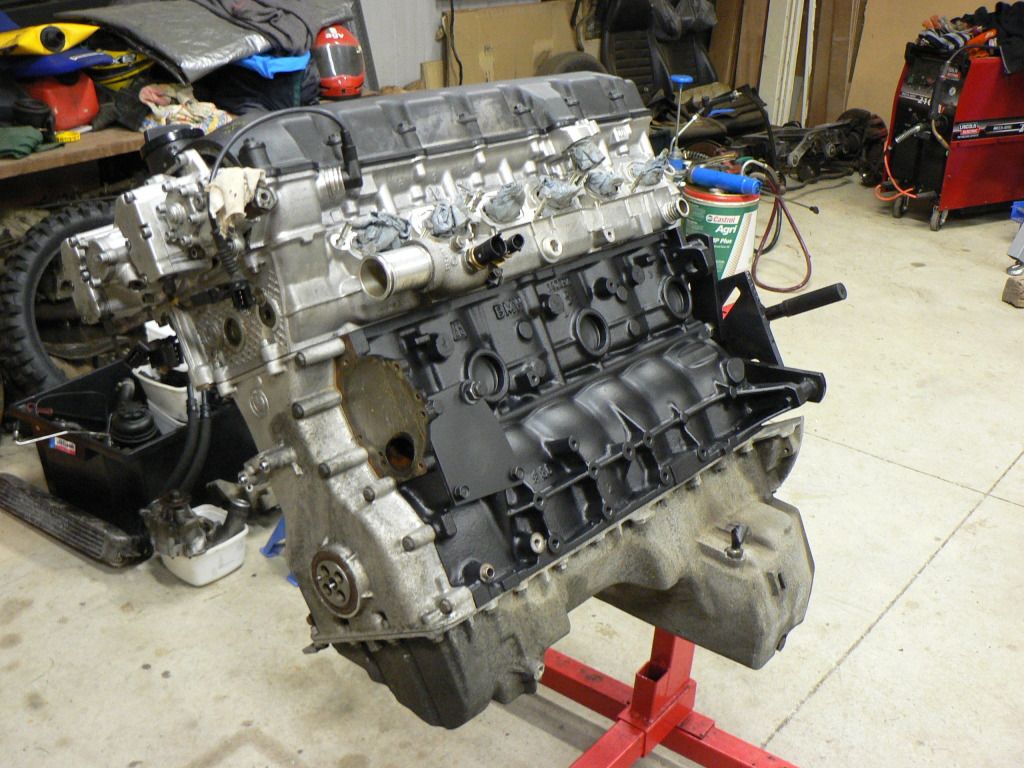
So 5 weeks ago I bought myself an early Christmas present. Had it bolted into the floor the following weekend and just needed a sparky to wire it, my brother suggested his brother in law so I approached him and he was happy to do the job as long as I wasn't in a rush, which I wasn't as I had plenty of other things to do.Eventually I had done all these things (more rust repairs) and was really ready to use the hoist this weekend and as luck would have it Mr. Sparky turned up and had it wired pretty quickly. Spec's called for a 30 amp circuit which seemed like overkill and was....... a load test revealed it was only pulling 7!Anyway, very excited to get the Z on the hoist finally. Will make life much easier for the Z and servicing other cars.Had a bit of inspiration last night after putting the car on the hoist for the first time........the engine and gearbox was sitting on the test stand next to it and I realised that it would be pretty cool to be able to load the whole lot from underneath by wheeling it under the car and dropping the body on the hoist over it.So this morning after an early coffee I decided that the engine test stand had done its duty as a test stand as the next time this engine runs will be when its ready drive in the car. I put the Z crossmember and mounts on the engine and raised it up 30cm to give me enough height to get under the car on the hoist and do up the transmission crossmember. I used the lower control arm holes in the crossmember for the extensions and just made a cradle to sit under the back of the trans at the back.Pretty chuffed with the way it worked out, it took all of 5 minutes to drop the body over the engine and do up the 6 bolts to secure it in place. I'm hoping that this will also work with the exhaust headers in place as well so that in the future if I ever need to pull the engine or gearbox I will be able to do it this way.It sure was good to see the engine back in its place again, gave a real sense of progress to see it there. I will be asking the engineers to come and inspect this ASAP. Looking forward to this with some trepidation!I needed to check a couple of things that have been niggling away at the back of my mind. I had never actually confirmed bonnet clearance for the engine....it looked like it would be OK but it was time to confirm so I pulled the old bonnet out and dropped it on......the throttle lever which the accelerator cable attaches to is the highest part of the engine and it just cleared as did the rocker cover at the front of the engine....phew!
-
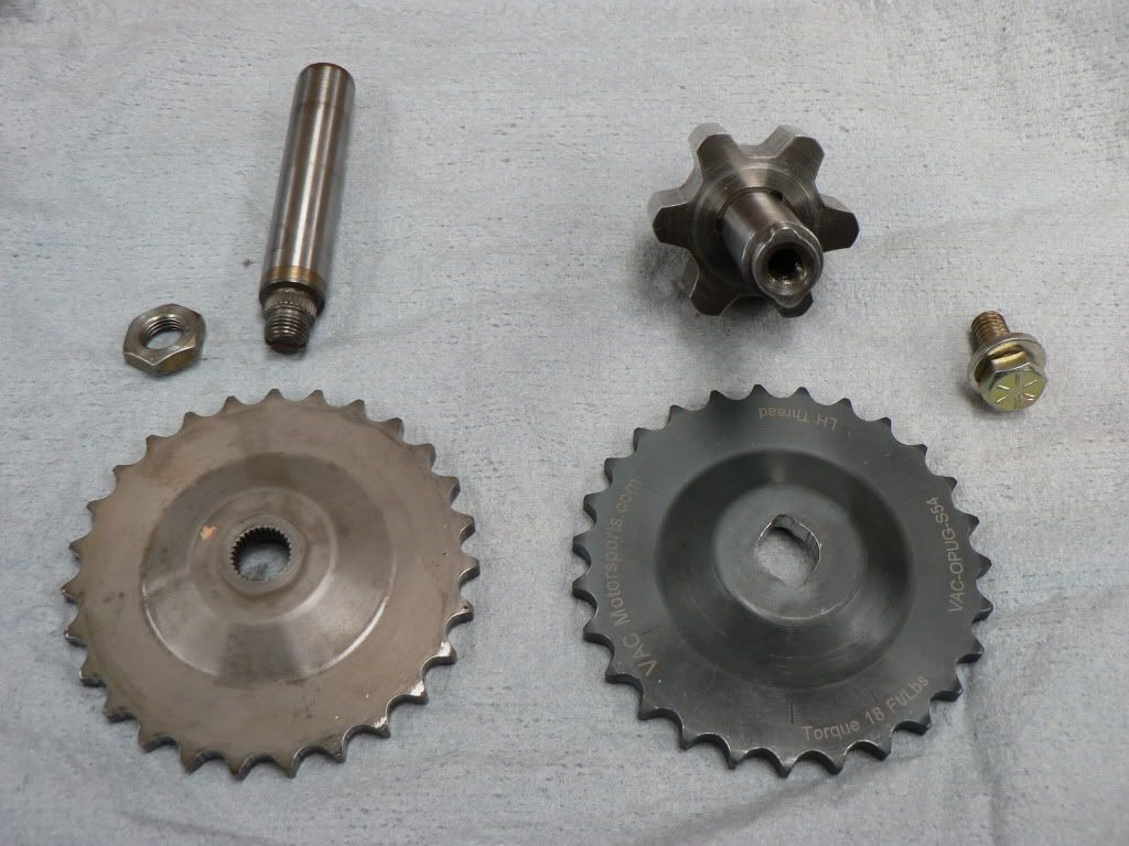
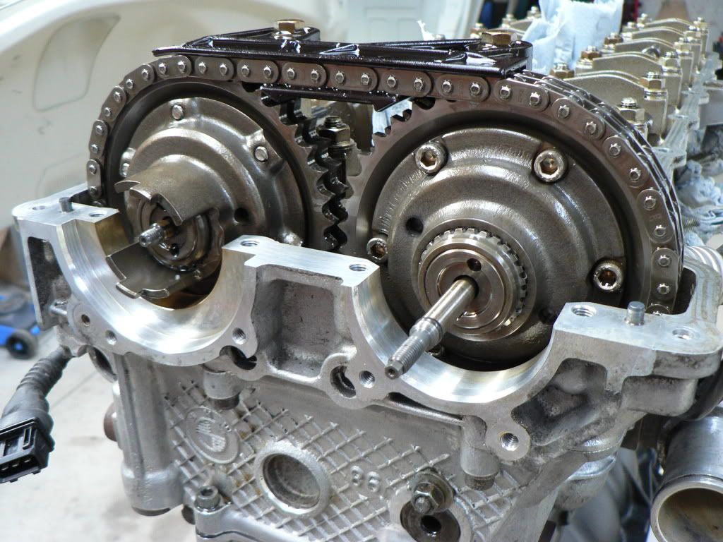
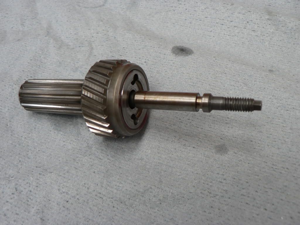
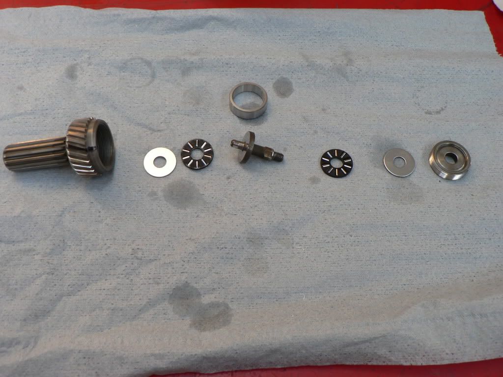
One of the other issues the BMW engines have is that the nut that holds the sprocket on the oil pump shaft comes loose with catastrophic results, this can easily be fixed by lock wiring or welding the nut however under extreme use they can also break the nose off the shaft off. While I'm not intending to race this thing I will use it for some track days and other events so I'm keen to do the most to ensure its as bullet proof as possible so I'm going with a VAC Motorsport oil pump drive which uses a keyed drive verses a tapered spline which solves both issues of the nut coming loose and the nose of the shaft snapping off.
While I was ordering the VAC Motorsport oil pump drive I also ordered one of their -10 AN oil cooler line adapters which is required if you cant use the factory oil cooler lines.
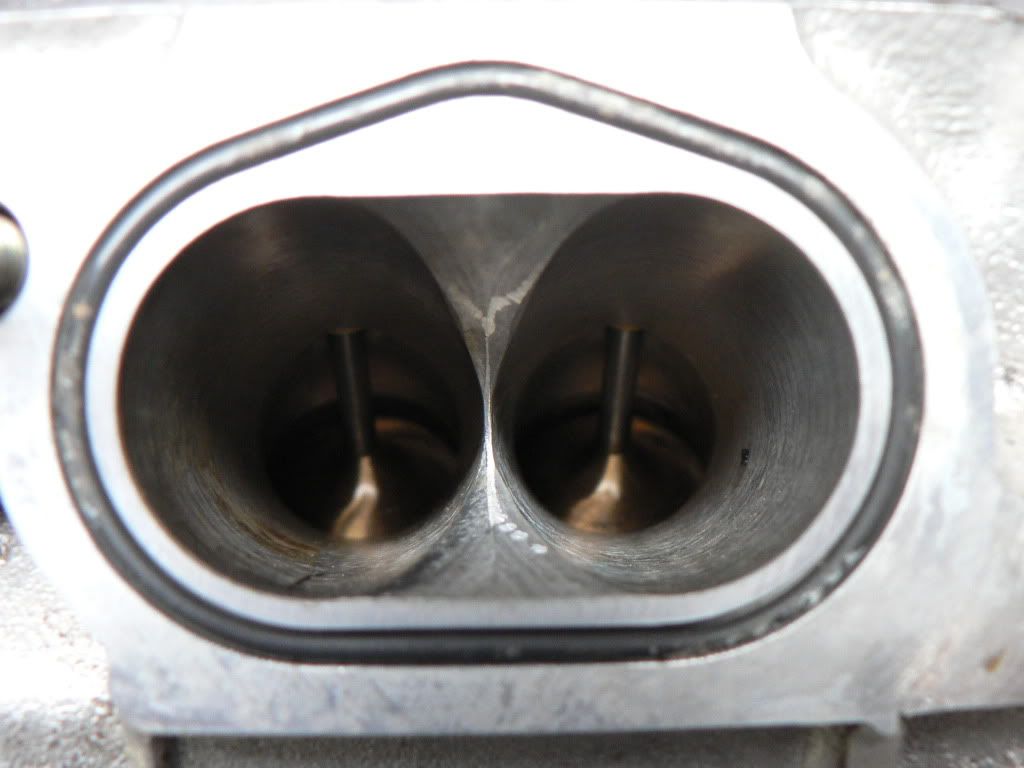
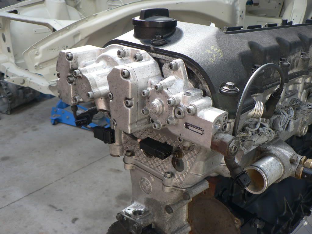
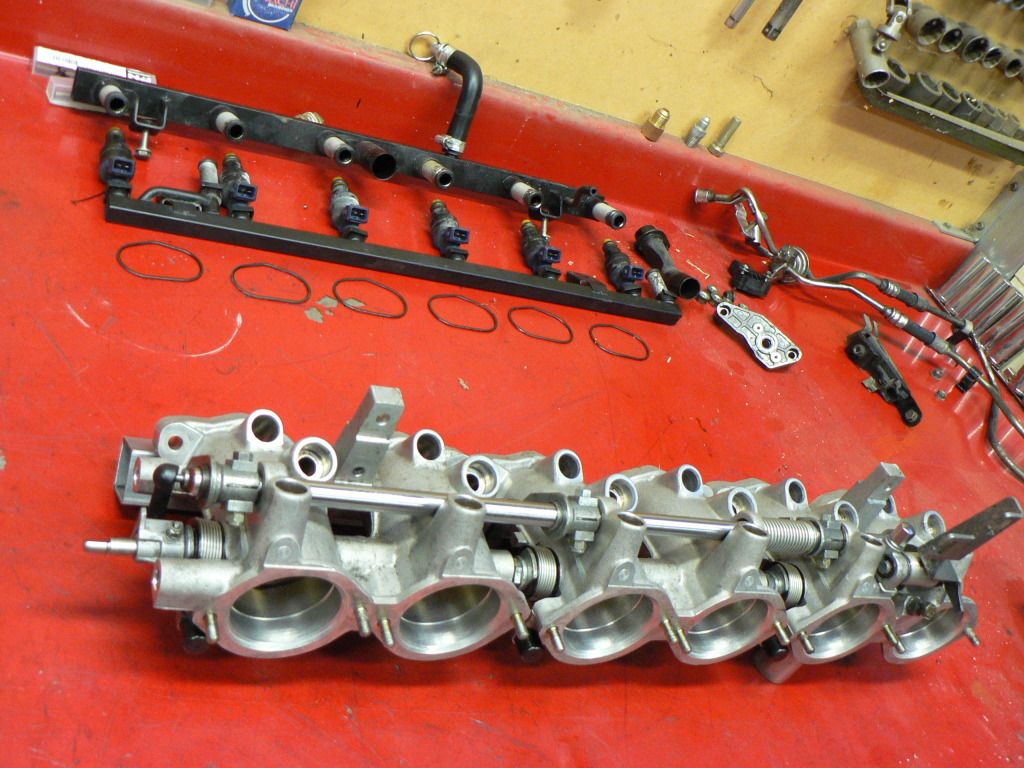
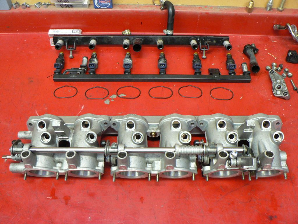
The top end is back together as is the bottom end with new front and rear main seals so I'm now reassembling with new gaskets and O rings where ever possible. I was putting the ITB's back on and thought I would share a photo of the inlet port....pretty nice for a production engine.
Hare & Forbes had a discounted offer on these https://www.machineryhouse.com.au/S302 in the last issue of Street Machine........
My poor misguided brother has a thing for FX-FJ Holdens and has two restos on the go at the moment, a ute and a sedan so between the two of us he needs one of these more than I do! He also has a big ass compressor at his factory so we struck a deal and will share the blaster at his factory. I figure it wont take long to recoup what it cost and the convenience of having one to use at any time will be brilliant as I start prepping and reassembling the drive train and suspension parts.
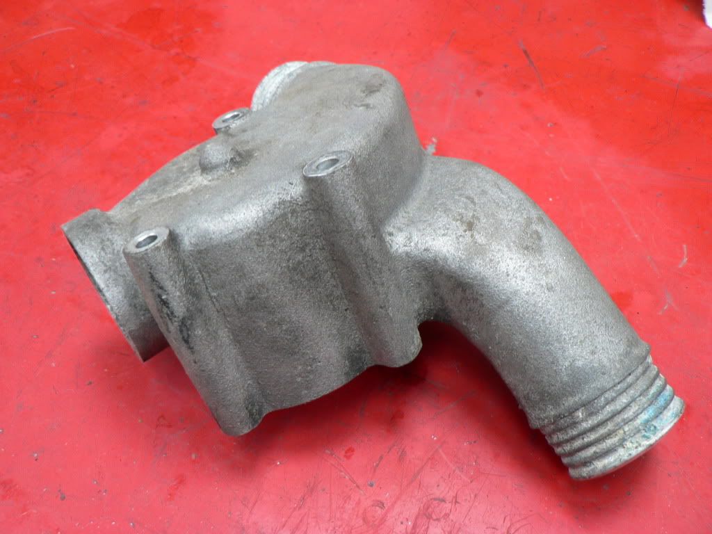
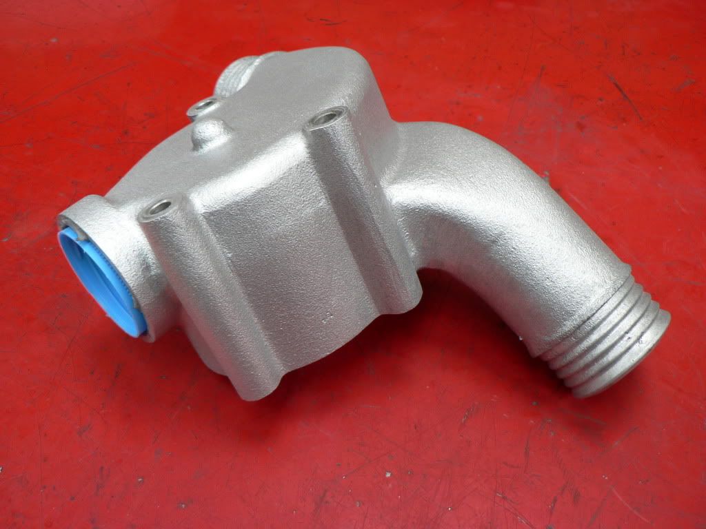
The sump and oil filter housing I had Hydroblasted, came up fantastically but it wasn't a cheap option and the guy is a long drive from my place so I bought some glass beads for the blaster and gave it its first run on my badly coroded thermostat housing and the serpentine belt tensioner. Very, very happy with the outcome. It was easy to use and very controlled and the end result was nearly as good as the Hydroblasting, not as shiny but a more factory finish anyway.
Before's and after's:
-
Hi Frank.
Thanks for posting pics of your B30 sump mods. Ive sent you a PM asking fior more detail.
Just to be clear my engine is a S50B32 but I have to run the S50B30 sump to clear the steering rack. B32's alreday come with the restrictor installed from the factory.
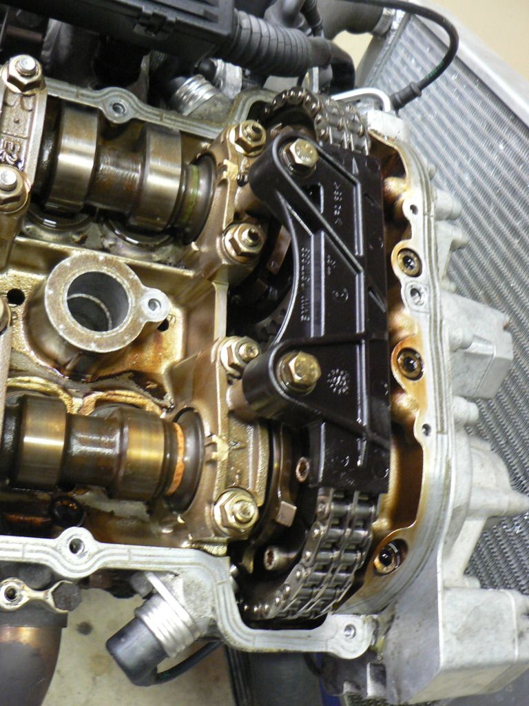
The M3 engine ran fine when it was on the test stand but they do have issues with the Vanos (variable cam timing) system. The Vanos system has solenoids controlled by the ECU that directs high pressure oil (there is an additional oil pump inside the Vanos housing to boost pressure over what the main engine oil pump provides) to cylinders either side of a piston that is connected to helical splined gears on the camshaft, as the piston moves back and forward the helical gears then either advance or retard the cams. First issue is the seals inside the cylinders are underspeced for the application and they degrade and then leak internally which results in the cams being in the wrong place at the wrong time so poor performance.
The second issue is noise. The 'diesel rattle' that is heard can be attributed to the helical splined gears that fit at the back of the vanos. Each splined gear has a bearing assembly inside which allows it to spin freely with the camshaft. These bearing assemblies are designed with a very loose tolerance from the manufacturer causing them to rattle or resonate at certain RPM's.
Besian Systems markets both seal kits and rattle kits, which cost $200 all up delivered from the US . Figured I would have to do this eventually and its better do the job with the engine out of the car.
The job isn't particularly difficult but takes a long time (second time would be much quicker) and its easy to miss time the cams if your not careful. The procedure instructions on the website http://www.beisansystems.com/procedu..._procedure.htm
http://www.beisansystems.com/procedu..._procedure.htm are very detailed and accurate and if you take your time and double check everything you wont go wrong. Hardest part was installing the Teflon seals....stretching them without breaking or damaging them.
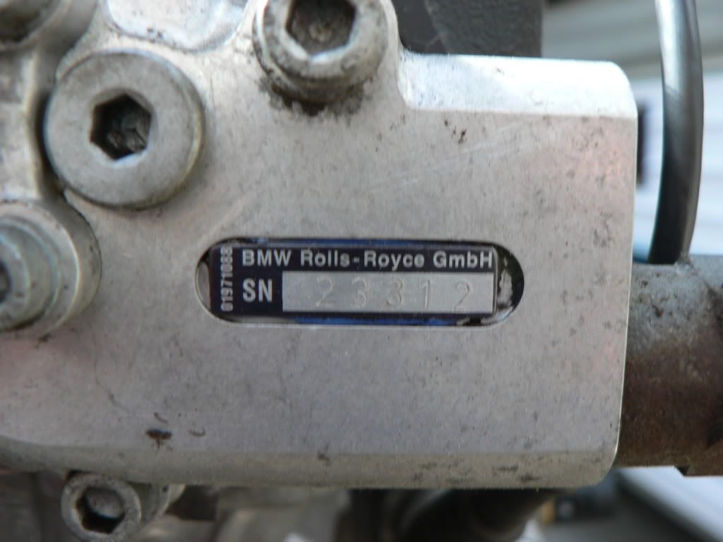
The reason why Vanos units are problematic.......Rolls Royce is involved! Like many things RR build its over complicated and quirky. I work in the aviation industry and their large turbofan engines are more complicated than everyone elses, when they work they work very well but they aren't the most reliable either.
The inlet cam piston seal which normally gives the most problems was definitely shot on mine so I'm glad I did the seal kit.
The rattle kit was pretty straight forward but like the seal kit took a fair bit of time to get the clearances just right and the tools that Besian sell are a must have.
It takes a few assemblies and disassemblies to get the clearances spot on. The aim is to have a slight amount of preload on the torrington bearings once the end cap is torqued down so you have to keep taking small amounts off the ring to sneak up on it.
Back together again.
I'm going to run the engine on my test stand again just to be sure its all good. My engine definitely had some Vanos rattle, not too bad but it will be intersting to compare with the rattle kit fitted.
-
Looking good! The s50b32 oilpan modification is very common on s50b30 track cars here all you need now is the same as my track car... A CSL type airbox
(carbon) and alpha n software. It ups the hp about 20 hp.. And in à light s30..you will notice it. Plus it raises the rev limitor to 7800 And THE best.. THE sound!!!!Once the car is sorted and running well I will go with a carbon air box and alpha N tune.....not for the 20 hp, just for the sound!
Unfortunately Im stuck with the B30 sump due to the B32 sump interfering with the steering rack so will go with an Accusump for insurance.
-
You mean the transit engineers will sign off on the engine swap but not the rear end swap ?? That's backwards isn't it ?
Not really, the engine swap is a bolt in deal that doesnt effect the structual integrity of the chassis. Fitting the whole BMW rear suspension would require major structual changes and re engineering. On the other hand fitting the BMW diff would be a lot easier and I did contemplate this but good ratio's are very expensive and hard to get. Its not likely I will break the R200 anyway.
-
Would keeping the whole BMW rear be too complicated? I read somewhere that the BMW is only 3" (7 cm) wider than 240. Couldn't that difference be compensated with wheels?
Thanks liro, keeping in the spirit and staying with a NA six was the reason I went with the M3 engine. Hoping it turns out to be as much of a buzz to drive as I hope.
Anthing can be done with time and money but you have to ask if its realistic and truly beneficial. Engineers need to sign off my car so I can leagally drive it on our roads so while the whole BMW rear could be fitted it would make it much harder to get signed off by the engineers compared to staying with standard suspension and an R200. Just not worth it in my books.
-
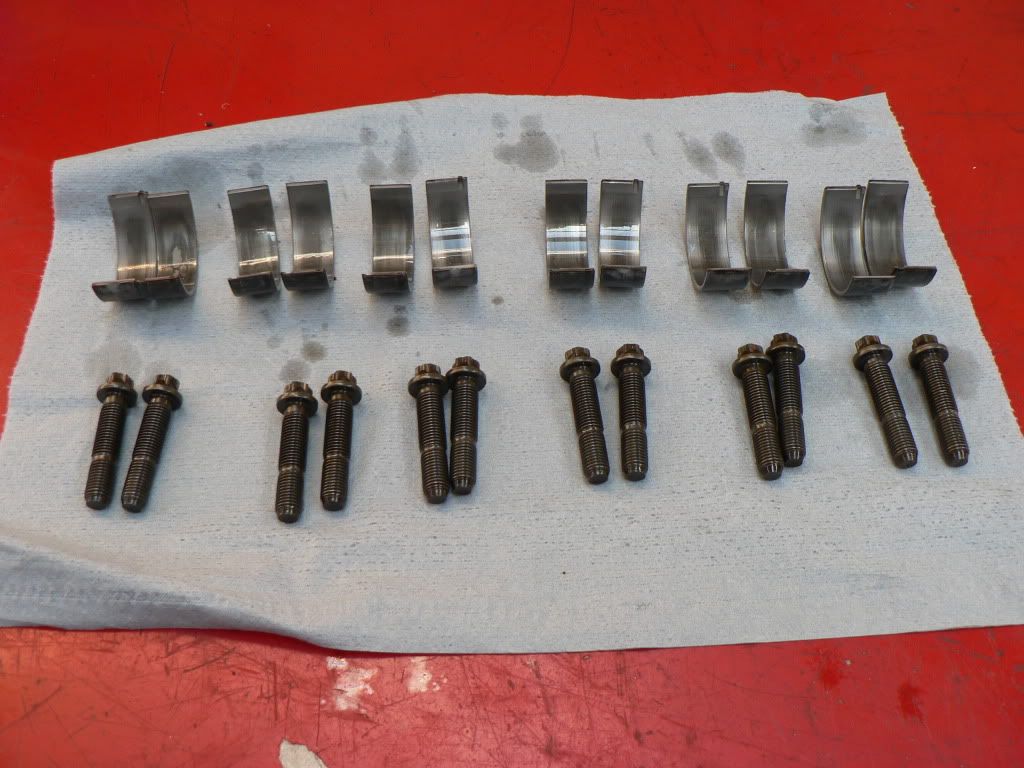
Big end bearings and ARP rod bolts are fitted.
BMW use colour coded bearing shells to get the clearance exactly right but they wanted $50 per half shell and they were ex Germany. Also I was doing the replacement with pistons still in the block as I don't have the special tools or the desire to remove the head so measuring and selecting colour coded shells was a no go.
I did lots of research and checked with BMW specialists in the US and Europe and found out that many re-brand and sell bearings under their own brand and turns out these are actually ACL Race Series bearings. They all (as expected) recommended them so I took the plunge and bought a set through Bursons. They come in STD, STD + .001 and two undersize so I just ordered a set of STD, for $176 if they didn't give me the clearances I want its not a big deal compared to the minimum $600 from BMW.
The old BMW bearings measured up with 1.5 thou clearance using plastigauge for all six, even the one with the top layer starting to come away..... you couldn't feel this with your finger nail so it looked worse than it was. Old bearings and bolts below.
The ACL's measured up at 2.0 thou across all six, a little more clearance but still well within the BMW spec which is 1.0 - 2.7 thou....got me stuffed why they have such a broad spec given they go to the trouble of coded shells?
I also bit the bullet and bought a rod stretch gauge, only a cheapie for $89 from VPW but the dial gauge spring wasn't strong enough to support its own weight so a couple of strategically placed rubber bands fixed that and it worked well after that. ARP quote 50ft/lb for these bolts but are adamant that stretch method is the way to go so it was interesting to see the variance in torque required to get the desired .0065 - .007 stretch. Lowest was 50 ft/lb and the highest was 62 ft/lb with most around 55 ft/lb.
It all turns nicely so that's a good thing.
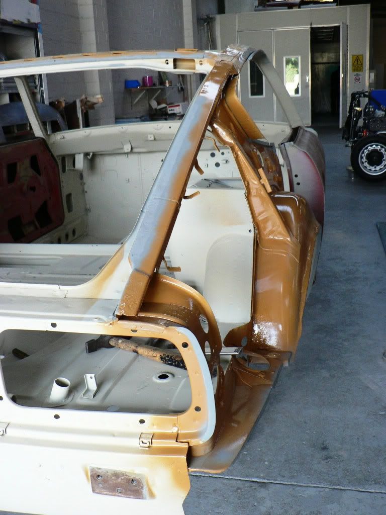
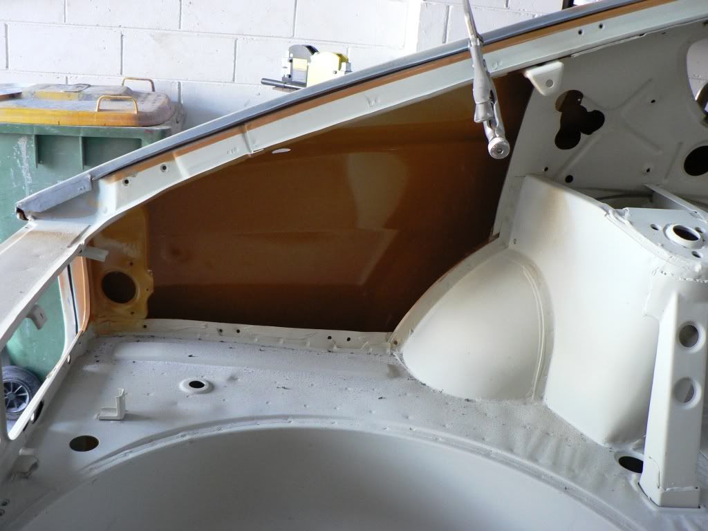
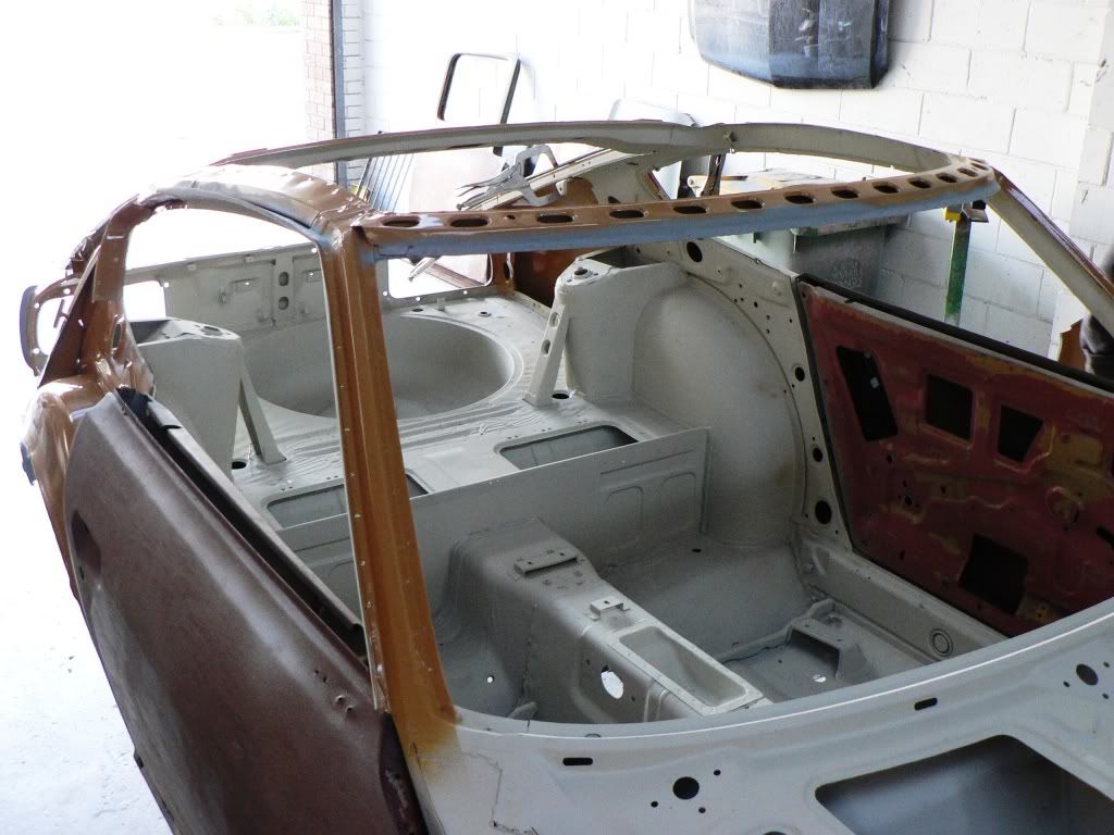
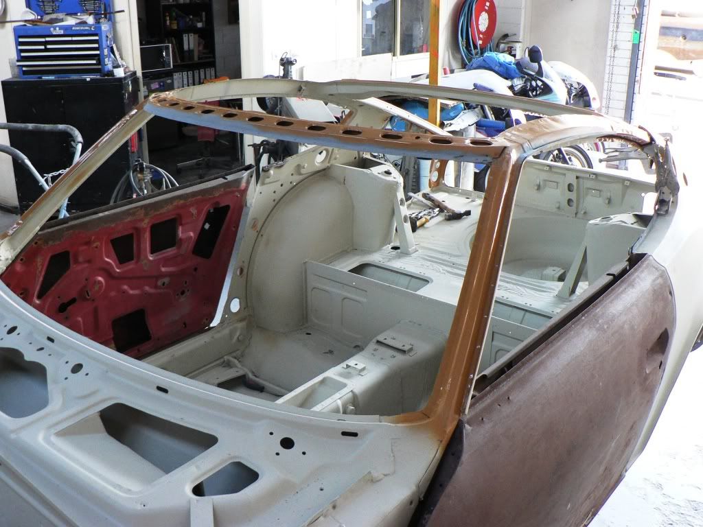
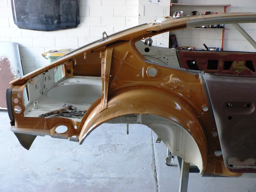
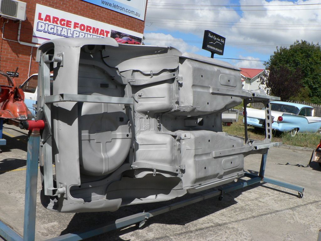
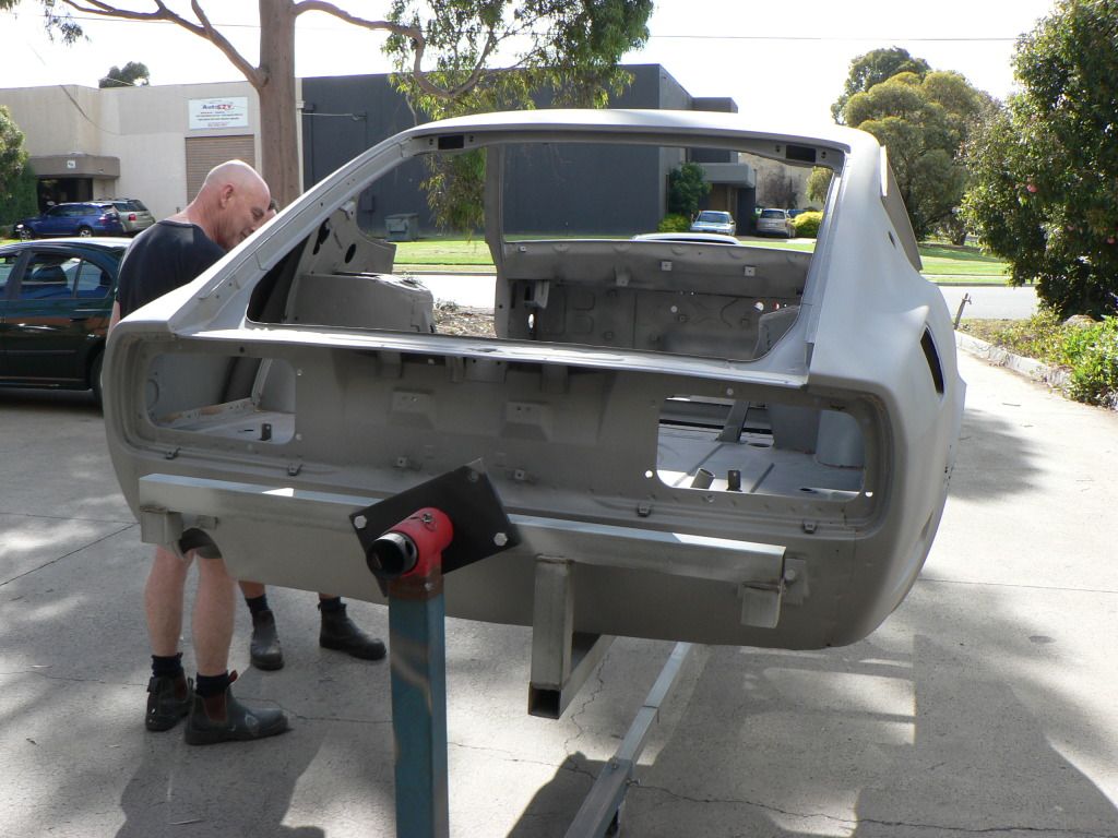
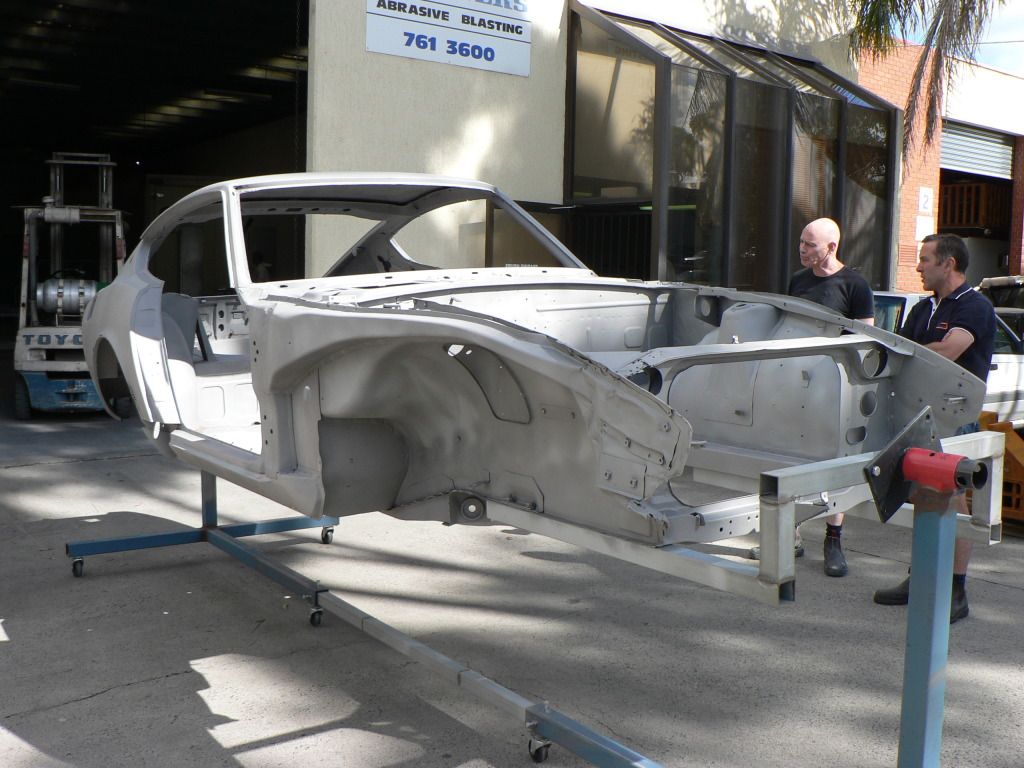
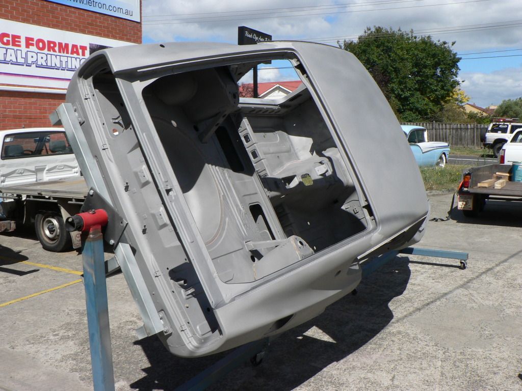
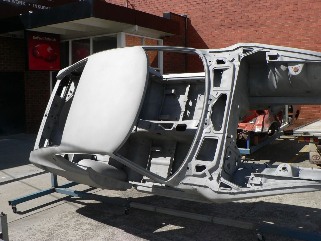
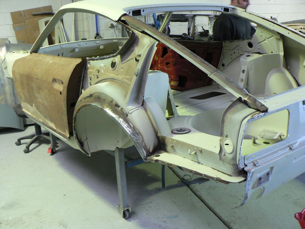
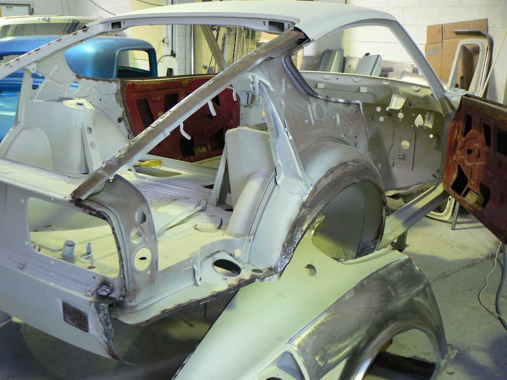
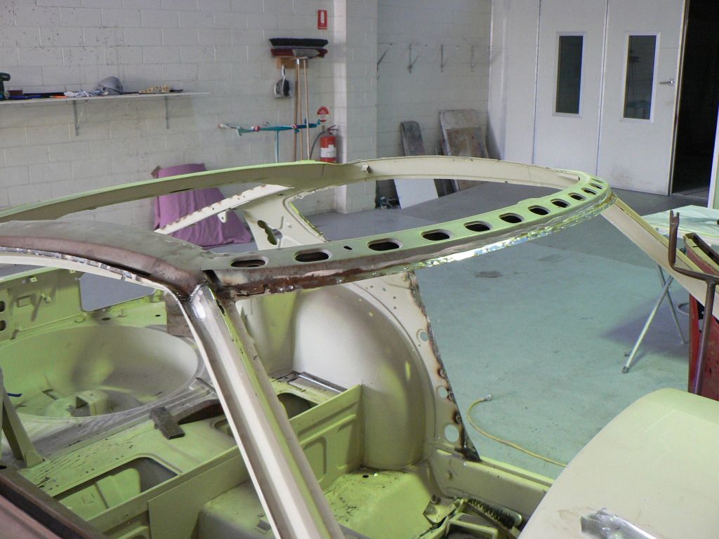
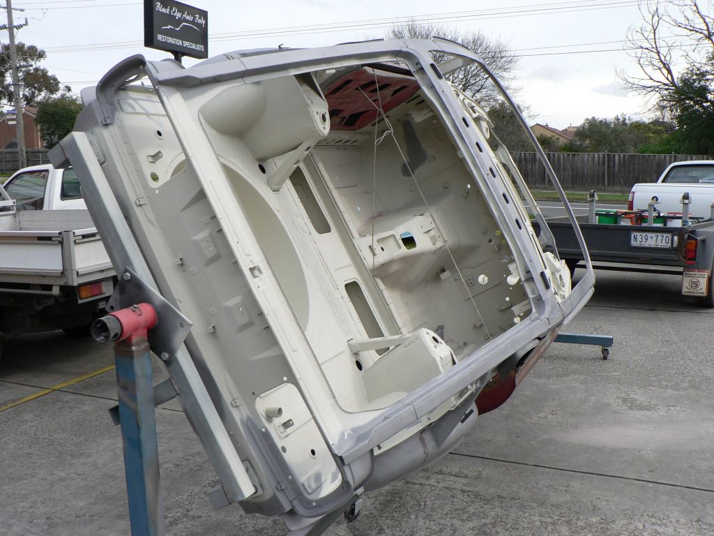
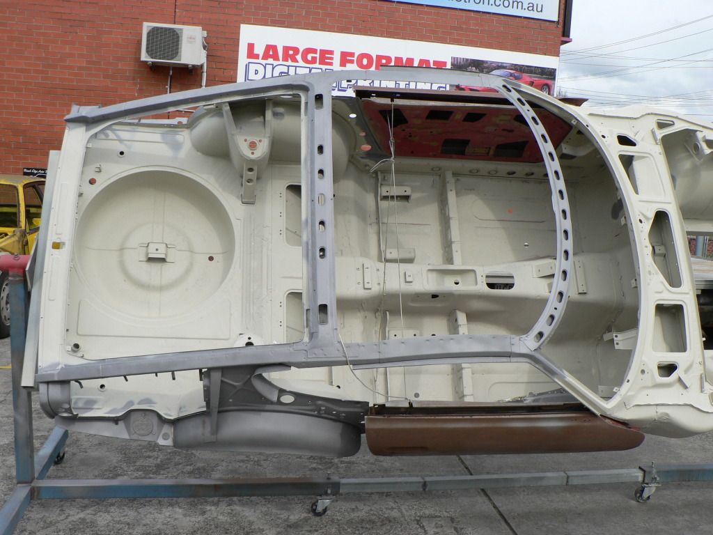
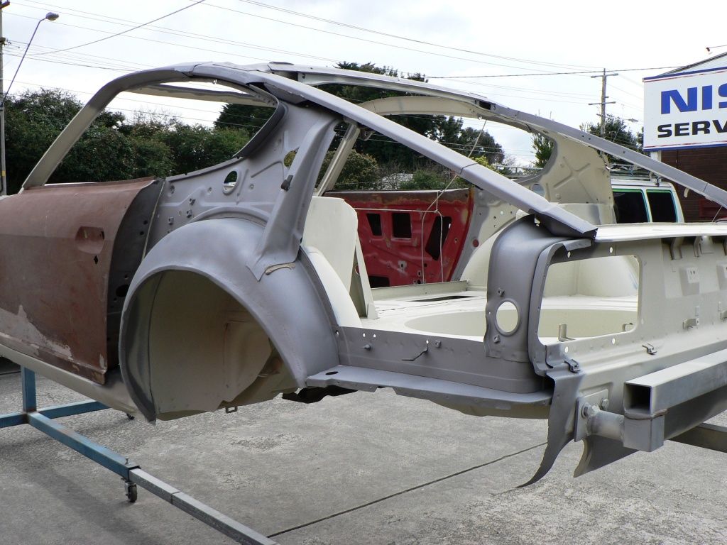
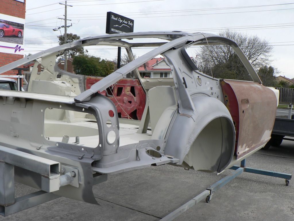
Quarter panels and roof skin are about to go back on. They painted everything that had been exposed and blasted during the removal and used weld through primer in the required areas. Will hopefully have the car home again in a couple of weeks so the engineer can inspect all the mods and hopefully give the OK!
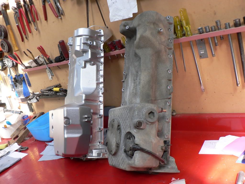
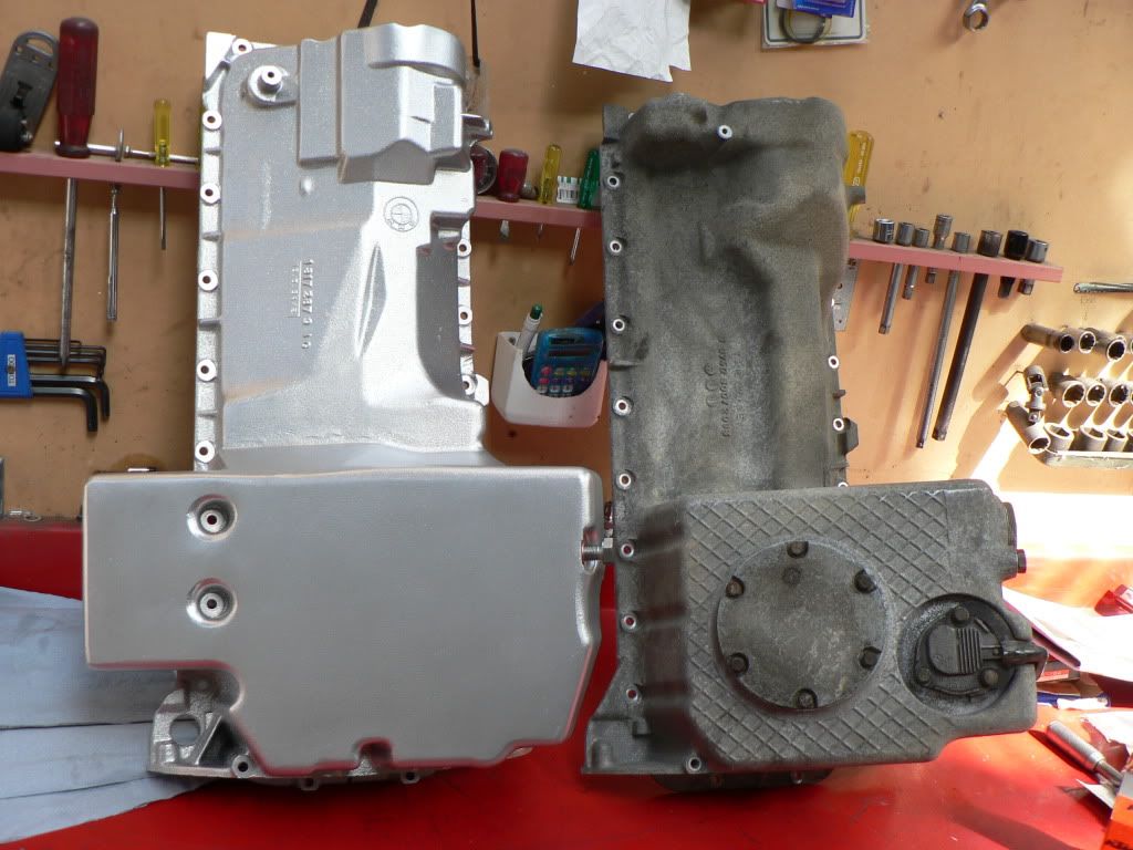
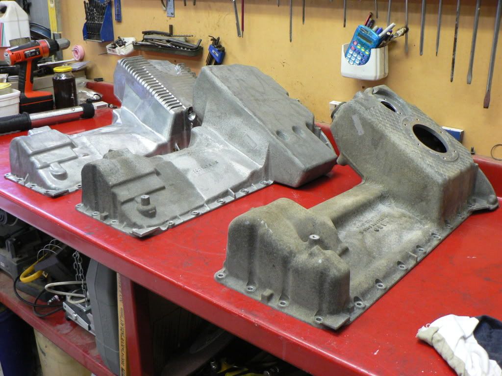
I had been looking at alternatives for cleaning/restoring the sump and oil filter housing as they were badly corroded from the salted roads in the UK. Research says that hydroblasting is the way to go to get an as new finish. Im blown away by the quailty of the finish, it actually looks better than new, nearly fake its that good.
Hyrdroblasting is like glass bead blasting but using water rather than air.
Cost is $1.00 per minute, both items ended up costing $150. Not cheap but I think well worth it for something that looked terrible before.
On the right is my old S50B32 sump for comparison.....the S50B30 sump was actually even worse beforehand.
The oil filter housing was just as bad.
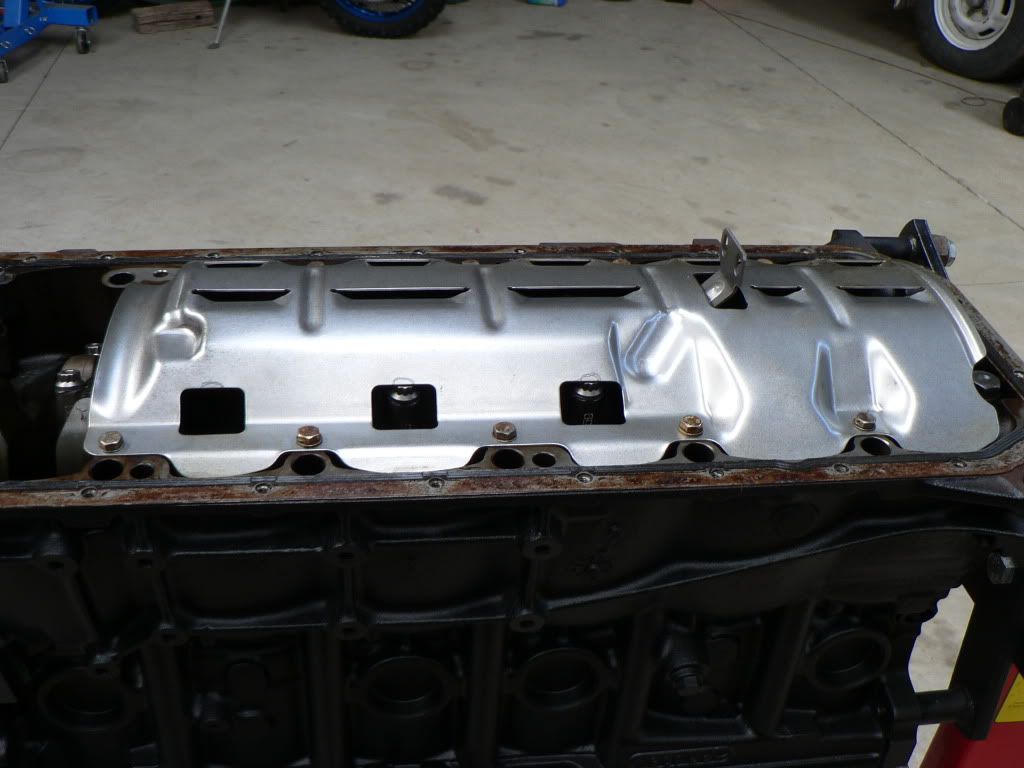
Now that the bottom end is back together I could refit the windage tray that gave me a heart attack when I first started the engine on the test stand. This tray is from the S50B30 engine and the longer stroke on the B32 engine means there isn't sufficient clearance.
The ARP bolt heads also stand a bit taller than the factory rod bolts so the rods 2, 3 and 4 were hitting the windows in the windage tray much more than previously. Some judicious filing and checking had it fixed and turning over with no other clearance issues.
-
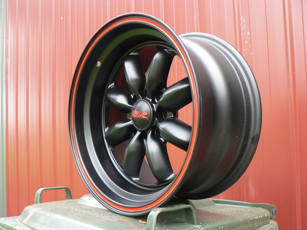
Some how 18 months have gone by!After getting the engine running on the test stand I wanted to check for any codes it was throwing. I used a Peake tool and it was throwing the following codes:A2 Synchronisation Cam SensorOA Output Camshaft SensorIt was throwing other codes but that was to be expcted as it wasnt seeing lots of body related inputs but that was inconsequential.I figured the two codes are related as the ECU needs to know positions of both cams relative to the crank at all times, logic being that if one sensor is crook it will spit that code as well as cause the lack of crank/cam sync. So looks like Ive got a crook cam position sensor...but which one? there is no way of testing the actual sensors without going on the you beaut diagnostic computer at a dealer so I was looking at replacing both sensors. Took a month (they were ex the fatherland) but Pelican Parts came through with 2 x genuine BMW cam position sensors @ $97.00 each plus freight, to my door was $220 vs $800 from the local stealer. Should be a law against that obscene mark up!What I thought would only take a few minutes took an hour as I had to pull the rocker cover to get access to the Allen head bolt for the inlet sensor and even then it needed a cut down Allen key and a bit of patience to get it done.Gave it another run with the Peake tool and all was good, no more codes of any consequence!Meanwhile, a member on the viczcar forum had some wheels for sale. Hadnt seen these before but fell in love when I saw his add. I want old skool but tuff and reckon these fit the bill perfectly.Ron provided the drawings and a keen Z enthusiast who owns an engineering shop soon had this whipped up.I was contemplating using the M3 diff as the ECU needs the road speed signal from the sensor on the rear diff cover which is sent to the dash (for the speedo signal) before it is modified from a simple square wave to a signal that the ECU can use. If the ECU doesn't see this signal it goes into a limp mode with reduced RPM's, the signal is also the 155mph speed limiter. In the end I found a company in Belgium that makes a box that produces a synthetic signal for the ECU that also removes the speed limiterThe speed simulator isn't cheap but without a donor car and an oscilloscope there was no way for me to reproduce the modified signal and while I could make the BMW diff fit the cost of custom CV shafts and the extra weight and attention this would attract at Rego engineering time just wasn't worth it.While all this was going on was doing a lot of rust repair work. Work that I felt competent enough to do anyway. The plan was always to have a panel shop do the final panel work, prep and paint so the next step was to get the whole shell blasted. I was promised by the blaster October 2011 which then was delayed to December and then into January of 2012. Finally it was done early Feb, I was pretty pissed off with the delays but the horror stories I have seen and heard about warped and damaged panels made me determined to wait as this blaster hed a great reputation. I was stoked with the job the blasters did, very very thorough and no damage to any panels. It was well worth the wait.Shell was shot with epoxy etch on the same afternoon after it was blasted.Time went by and after a couple of months of no action at the panel shop I cracked it and read the riot act and pushed then to get into my car....they have a lot of cars in the shop and its only a two man show....Glen the beater and Allan the painter but that is testament to the quality of work they do.As expected the blasting revealed some dreaded cancer that wasnt evident before hand....and thats why you do blast....so you really can see what you are working with. Blasting revealed that there was significant rust in the lips of both rear guards. There is a big chunky bead of seam sealer that the factory filled between the inner and outer guards all the way around the lip and this just collects moisture and has the obvious effect.I talked with Glen about options and he was adamant that removing the rear quarters was the only way to tackle the repairs properly...rebuilding both the inner and outer guard lips. They have a matching numbers E38 Charger in the shop with the same issue and Glen showed me what they had done and I after seeing this I was convinced that this was the best route so ff they came......And the roof skin for the same reason!By now most of the repairs that Ive asked the panel shop to do are nearly completed and the rear quarters and roof skin were now ready to go back on but before they do the car went back to the blasters so all the newly exposed bits can be blasted.Had to go to the panel shop, take the car off the rotisserie, put it on the trolley, put the car/trolley on the trailer, drive to the blaster (only 5 minutes away luckily), take the whole show off the trailer and stick it back on the rotisserie, have it blasted then repeat and return to panel shop! Phew!Photos are after blasting back at the panel shop. As with their previous work the blasting was very thorough and top notch.Blasted bits will be back in epoxy etch by now and then these areas will get shot with final colour before the panels go back on. Weld through primer will be used for the areas that need to be spotted back together. I keep trying to convince myself its all worth it.....I think it is.So back to the BMW stuff...The engine has been on the test stand for nearly a year, Ive run it a few times just for kicks and to keep it dry and lubed. One thing I hadn't done was check if the engine speed signal from the BMW ECU would drive the Speedhut tacho, turns out after selecting the correct pulse type it works fine. Pretty cool tacho....fully programable, recall, shift lights etc cant wait to drive it for real.Next thing on the agenda: is to strip the engine, do big end bearings, ARP rod bolts, VAC oil pump drive, front and rear oil seals, CO2 blast all the discoloured aluminium housings including the sump, new gaskets where applicable, paint the block etc etc. To do this I had to remove the engine wiring harness, its a one piece pretty big bastard loom and took some doing to remove. Will be stripping out all the non required bits and also doing what's necessary to rewire to suit the Z battery location and to install the ECU inside the cabin as in the BMW the ECU sits in the engine bay.I had a sudden attack of OCD and spent hours in the shed cleaning throttle bodies. Mine were pretty disgusting, plenty of built up crud and generally just looked less sexy than they deserved. Used a kero based solvent and brushes (mainly tooth brush) to do the cleaning, it was a PITA but worthwhile. Didn't want to use any aggressive chemicals as there are seals for the butterfly shafts and I didn't want to discolour the aluminium finish either.OCD was still raging so I spent many hours degreasing and cleaning the engine. The exhaust side was pretty easy but the inlet side was a pain, plenty of rust and crap from the lovely salted snow and slush off the UK roads. Preped it as best I could then hit it with some matt black VHT. Came up really well.As you can see the cast alloy sump looks like a POS. Its been hot tanked but didn't do much to get rid of the dark oxided/staining. I'm looking for the as new factory cast alloy finish and Ive done a fair bit of research. Dry ice blasting was a good initial choice but its too expensive so I'm going to give Hydrablasting a go.Sump is now off and I pulled all the rod caps last night and all the big ends were showing some minor marks but #6 upper was the worst with a small section of the first layer starting to come off, nothing really serious and the crank was fine but reinforced that it was wise to check. The BMW fractured rods are the first time Ive had hands on experience with this design and they are freaky weird things!!! Looks just plain wrong but I understand the logic and benefits behind it.End of a long post but this brings me up to date.Cheers.David .
-
SeanD.
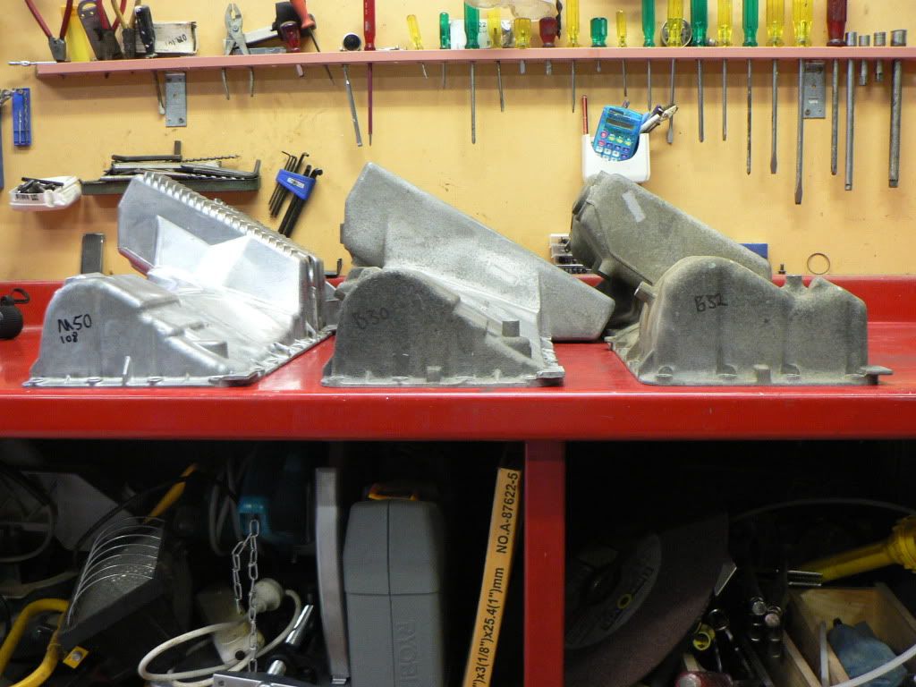
The S54 uses the same dual oil pump and semi dry sump as the Euro S50B32 and this sump interferes with the front cross member and steering rack. You could make it fit but your driveline angles will all wrong. Ive used the sump and single oil pump from a S50B30 (earlier 3 litre euro M3) but you could also use a standard M50/S52 set up as well.
Picture shows how much deeper the S54 sump is at the front. Left to right are M50/S52 then S50B30 and then S50B32 (same as S54).
Check my build thread for more details. http://www.viczcar.c...c,6400.135.html
Hope that helps.
-
Momentous occasion for yours truly..... and I was inspired enough to post my first YouTube video.To say I was relieved when it started straight away is a massive understatement. Bit of pain along the way but lots of win in the end!Watch all about it...


S50B32 Euro M Powered 240
in S30 Series - 240z, 260z, 280z
Posted
Took a while longer than expected Ron but got there in the end.
Thanks again for all of your help.