

Kirby260
-
Posts
46 -
Joined
-
Last visited
Content Type
Profiles
Forums
Blogs
Events
Gallery
Downloads
Store
Posts posted by Kirby260
-
-
So I need some new axle nuts and I would prefer the 280zx style cone-nut style.
I called Nissan spares here in Australia and they wanted $22 FREAKING DOLLARS (+ TAX) EACH!!!!! for a NUT!
eBay didn't have any listings and there wasn't many other avenues here. Anyway pretty much any US Nissan parts site has them for >$5 + shipping.
All you have to do is choose your favourite Nissan parts retailer, buy 4 of them and ship them to me in Australia.
I will paypal you all the costs + some beer money for your trouble. But the real payment is the warm fuzzies you get from not having Nissan Australia violate me for almost $100 for 4 axle nuts.
And if you ever come to Australia I will also buy you additional beer.
First person to volunteer gets the gig.
Thanks.
-
Dean,
Trying to get some info on your swap. Check your PM's.
-
So I sent an email to speedway engineering for parts:
0090-046 (12.437") (driver's side)
0090-046 (12.937") (passenger side)From the other thread, I got a response this morning.
They still have drawings (they just are no longer a stocked item), price is $217ea machined to order, 3 week lead time.
Almost to easy.
-
Hey Guys,
I was wondering if there had been any progress on the axle part numbers, I currently have:
- A Z32TT R230 VLSD (3.69 ratio)
- Techno-Toy-Tuning Forward Diff Mount
- Techno-Toy-Tuning Machined Mustache Bar
- 4 matching 6-bolt CV joints (from 4x 300zx driveshafts)
- Chequred Flag Racing 27-Spline companion flanges.
The only thing I'm missing are the axles and the modified C.V. end caps to adjust the plunge.
I was getting ready to order these from Ross, when he got sick and stopped accepting orders.
Its the last little bit I need to finish!
Apparently there is a speedway engineering axle that suits, but I don't have enough information, the C.V. end caps might be a custom machining job.
Anyone?
-
Hey Guys,
I'm hunting for a dimension from the rear hub geometry of a 1976 260/280z.
Specifically the dimension from the Hub (wheel mounting) Face to the Drum Brake Mounting Face on the Strut/Bearing Housing.
Attached is the estimation I have done on a poor drawing from the workshop manual, which I scaled from PCD and known bearing dimensions.
My estimated value is close enough to 60mm, that I would guess this is the actual dimension.
However, What I am looking for is for someone to validate this for me. I can't easily do this myself as my drum is still attached and I can't pull apart the strut at this point in time.
Any help would be amazing!
-
Hi Guys,
With Daves' Billet Brace/dogleg bar : http://arizonazcar.com/diffmount.html
It has provision for a "rear mount" sway bar. Does anyone know if this is just a regular sway bar flipped 180degrees?
Anyone had experience with this setup or care to comment?
Thanks
-
Provided it clears the steering rack and I can relocate the alternator, I'll be able to simply bolt the headers on backwards and mount the turbo in front of the motor.
The CAD is definitely a huge help. Solidworks is a dream to work in, especially 2009...
I hope to go down to Houston this weekend and do about 20 hours of work on mounting the engine. The tranny adapter needs to be machined, motor mounts cut and welded, and the engine hung in the bay.
Oh man. Want to share your part files for the chassis/engine bay, it would save my life doing my engine mounts for my swap
-
-
There a number of these type setup sold in Japan for the S30. I purchase one of the Japanese kits - it like many of the parts I have is still waiting for the body to return from the body shop. I agree with the above and as I have modified suspension (ready a lot more + caster and - camber) having PS for autox work will help. The kit I have includes a speed sensor so the EPS unit is only helping at low speeds at high speeds it is back to the normal zed rack.
Here is some pics of the kit that I got from Japan - including a sample installed into a Zed - there is a youtube video of a guy using this setup on the car shown in the sample pic attached. There is some fab work required and I will sort this out later - maybe a job over the festive season

what sort of $ there?
-
So are we going to see an install this weekend?
-
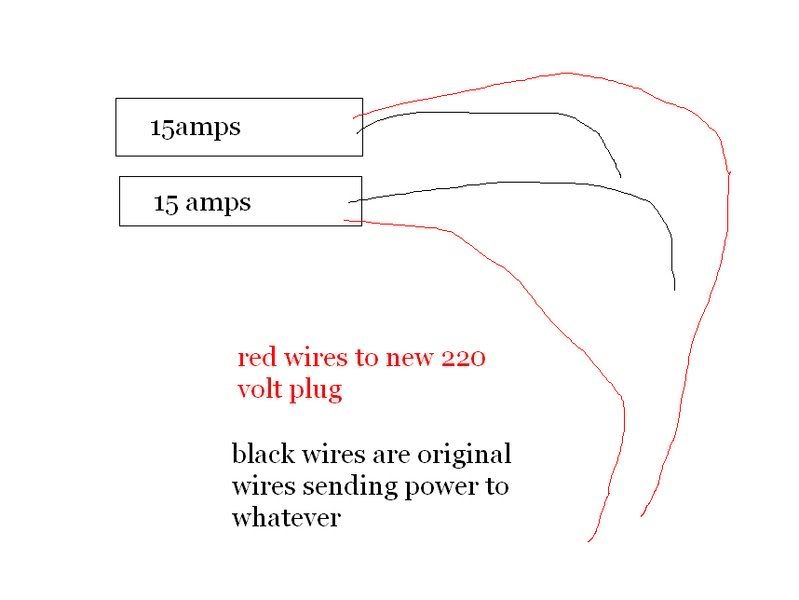
would this be ok and safe to do, tapping 2 single pole breakers?
GOOD GOD NO!
The fact that you even considered this as a solution means you don't have the knowledge or understanding to be playing around with this stuff!
Call a qualified electrician!
-
silvermine [gt500]-piston 1 5/8", rotor 11 13/16" dia & 3/8" thick-vented
3/8" sounds a little thin for a vented rotor...sure its not 3/4"??
according to this: http://www.dba.com.au/2006/PDF_CATALOGUE/Catalogue_AUST/2008_AUSTCatalogue_01102008.pdf
both the V6 and the V8 Mustangs ran a 300x19 rotor. (pretty close to 11 13/16" x 3/4")
and the GT500 ran a 330x20.7
now I'm just confused...
-
IIRC from an earlier thread, aren't they from a Mustang Cobra?
And since most brakes aren't made by the car manufacturer themselves, I doubt they are made by Ford. They look very similar to the calipers on my wife's Volvo which are made by Ate.
I would have a guess and say that they are PBR, which makes alot of stuff for GM and Ford. Do look like nice calipers!
-
Eagerly waiting to see more photos/results.
Can you give us some detailed measurements on the rotor?
-
From here...http://www.viczcar.com/forum/index.php?topic=3291.0
Its been done, and there are many variations to it. This is the DBA106B disc and R32 caliper and machined 260Z hub (not 240). Caliper mounting holes have to be re-drilled though.... -
Still haven't had the chance to contact Dave yet but....
http://www.arizonazcar.com/s13coil.jpg
looks VERY similar to
http://www.newstylemotorsport.com/hdsystem/HRtype.jpg
More info...
http://www.otomoto.com.au/HDSystems/
http://gsbcyhhao.en.ec21.com/company_info.jsp
Thoughts?
-
I've been doing electrical on amateur race cars for some time now.
Here is what I was taught about connections: (Doesn't mean I'm right)
-Never solder a connection meant for crimping
-Always use the right crimper for the type of pins (no pliers)
-Splices should be crimped with adhesive heat-shrink, for strain relief and environmental protection
-The only solder in the car should be on PCBs, Multi-link splices or Solder splices for cable shields.
-Every connector should have some form of positive lock. In the case of spade/bullet/screw-clamp connections. Friction is not enough. These connectors should NOT BE SEEN in any sort of high reliability application (or ever on a race car).
Things I Have seen.
-Spade connector on fuse-block falls off due to vibration. Fuel lift pump stops. Dropped out of race.
-Screw-Clamp connector on back of switch works itself loose due to vibration. Wire disconnects entire circuit stops working. Ended testing for the day.
-A Deutsch Autosport connector (solid crimp pins and everything) was used as the firewall connector. Someone used the wrong crimper on the pins, during the race, wires pulled from the connector and we lost and injector and a gearbox sensor.
Food for thought:
Commercial Aviation and Military standards both mandate crimping only (solid pins, radial crimping)..you will never find a solder joint in an airplane or any military (apart from PCB's, even then there are rules about component height for vibration).
Commercial Automotive uses pressed pins and crimping in all of their connections, once again, no solder. In the event of the need for a multiwire splice, they use splice connectors.
Automotive wire (SAE J1128) is multi-stranded to allow for sharp radius bends and flexibility. If you solder the wire, it becomes solid. Sharp radii, flex and strain at the junction between the solder and the individual strands WILL LEAD to a compromised joint.
-
Dennis Grant makes some good points in his website and I completely agree on the subject of dyno plots.
If a vendor is not willing to supply the plots either they don't have a clue what they are selling or they don't have confidence in their product.
I think it should be reaffirmed at this point that Dave (of AZC) has not actively denied supply of dyno plots for his dampeners...I haven't asked him. I don't think anyone else here has either.
He remains a great vendor and a huge support to the Z community...in fact I'm going to drop him an e-mail today.
-
Especially if you don't know what they are or how accurate that manufacturer is in general, dyno plots on all of them is the way to go. Otherwise, how do you know that the dyno plot you have seen is typical?
I suppose I could always ask Dave if he is able to supply these things.
I would probably stick them on the dyno here at Uni and balance them all up before they go in my car. Still it would be nice to know the general characteristics (and variance between units) of anything I'm putting in my car.
-
Jon's link shows exactly what I am looking for regarding the AZC struts.
I have heard people rave about them and I find myself leaning towards them. They do look like a nice and well priced package.
However, if 3 years of FSAE has taught me anything about suspension (I'd like to think it has) there is no use in (15-way) adjustable shocks unless you know what you are adjusting.
I'm not looking for dyno-plots for each shock I buy (much like Jon's link suggests). I'd be happy with a typical dyno plot of the strut showing the adjustable ranges.
If I could know what the manufacturer is, bonus, because then I can do some more research on the product.
They do look very similar to stance units, except stance have the adjustment knob on the top of the unit not the bottom.
I can't say what they are but they are not Stance.You don't know or you "can't say"?
-
Hey Guys,
I'm curious if anyone knows the manufacturer of the AZC coilover strut.
I've had a look, no one seems to mention it.
I'm looking for some data regarding the dampening adjustment on the unit.
Cheers,
Kirby
-
I'm pretty sure it comes of the GM 3800 V6. They have them around here in Australia.
Pretty sure its a 3-Coil Dual Post, with in-built firing transistors. Connectors are Delphi Weather-Pack (I think). Should be 5 or so connections. GND, +12, and triggers for all three coils.
-
hardpoints, datums and dimensions. floorplan.
-
Looks like you found the chassis blueprints from the FSM. I've modeled the 240Z in 3D, but my model is based purely on those chassis blueprints, orthrographic views in the FSM, and eyeballing my own car. I would love to see someone do this in CAD or another program, but use actual measurements from a real car to get it entirely accurate. That'd be very useful.
I am using the chassis blueprints from the FSM. It gives a lot of the structural hardpoints/datums. My hope is that a reasonable 3D sketch of these can be obtained. The next step is verification of measurements off my own car that don't appear in the FSM and the other reference drawings I have.
Then hopefully stitch all known points together with surfaces and sheet-metal assemblies.
I looked at creating the body work model from the orthographic reference drawings. How did yours turn out? Care to share higher-res/muti-views?


[WTB] 280zx Axle Nuts
in Parts Wanted
Posted
All good guys, z240 is going to sort me out.
Thanks.
I don't care if it goes by surface, it's not urgent!
But no matter how I cut it it's still cheaper. USPS also do good flat-rate parcels.