

Dave
-
Posts
350 -
Joined
-
Last visited
-
Days Won
2
Content Type
Profiles
Forums
Blogs
Events
Gallery
Downloads
Store
Posts posted by Dave
-
-
The 75 280Z has a shunt located under the fusible link shelf and it is held on by phillips head screws, kinda looks like a voltage regulator with 4 wires going to it. The ammeter reads off of It. There are 2 10ga and 2 small wires that send a signal in millivolts to the ammeter. Inside the shunt enclosure are 2 small fuses. If the fuses are blown or the wires to the ammeter are corroded the ammeter will not work. This is a different setup than the 240Z's use that run the full load through the meter.
I too find the ammeters a little scary, I changed the ammeter in my 240Z to a voltmeter from a 77 or 78 280Z. I just swapped the meters inside the gauge housing and connected the 2 10ga white wires together that went to the stock ammeter.
-
After not getting any real definitive yes or no answers to these devices I bought one and connected it the the wife's S10 JIMMY that was having a battery near death experience with a 4 year old battery. After just over a month in use I have found it appears to have brought the battery back.
At first it was powered all the time but the desulfator charges up and spikes the battery making radio noise when the JIMMI is running. I wired it with a relay that opens up when the ignition is on so the desulfator is off when the JIMMI is running. The desulfator draws only a few milliamps and can run for months without drawing down the battery.
Before I installed the desulfator the battery was at 12.83 volts and a 15 second 100 amp load test dropped the battery voltage below 9.4 volts. After a month in use the battery is at 12.89 volts but it only drops to 9.9 volts with a 15 second load test. Both tests were done in the morning after the JIMMI had been sitting all night. The big difference I noticed is in the mornings when its cold the JIMMI cranks a lot faster.
I bought the one from this place http://wizbangplus.com/ and will get another one for my Z.
-
It is interesting from the different videos how the Z evolved from
just a cutup Z to door jam braces to add strength to the subframe
to a full roll cage.
-
I love that show. I never know when its on though
That is Red Green in the video. Here is a how to convert your Z into a Hybrid back hoe
All wheel Drive Z
Hybrid riding lawn mower
Hybrid exhaust system, this is cool
-
-
Pop N Wood, Easier yet is to buy a light timer and set it to run your regular battery charger for 5 minuts a day.
-
Thanks for the input on this guys.
I have come to realize that there are a lot of ways to do this. There are a lot of little issues that crop up.
Dave,
The "I" terminal is beautifully simple. Thanks for the idea!
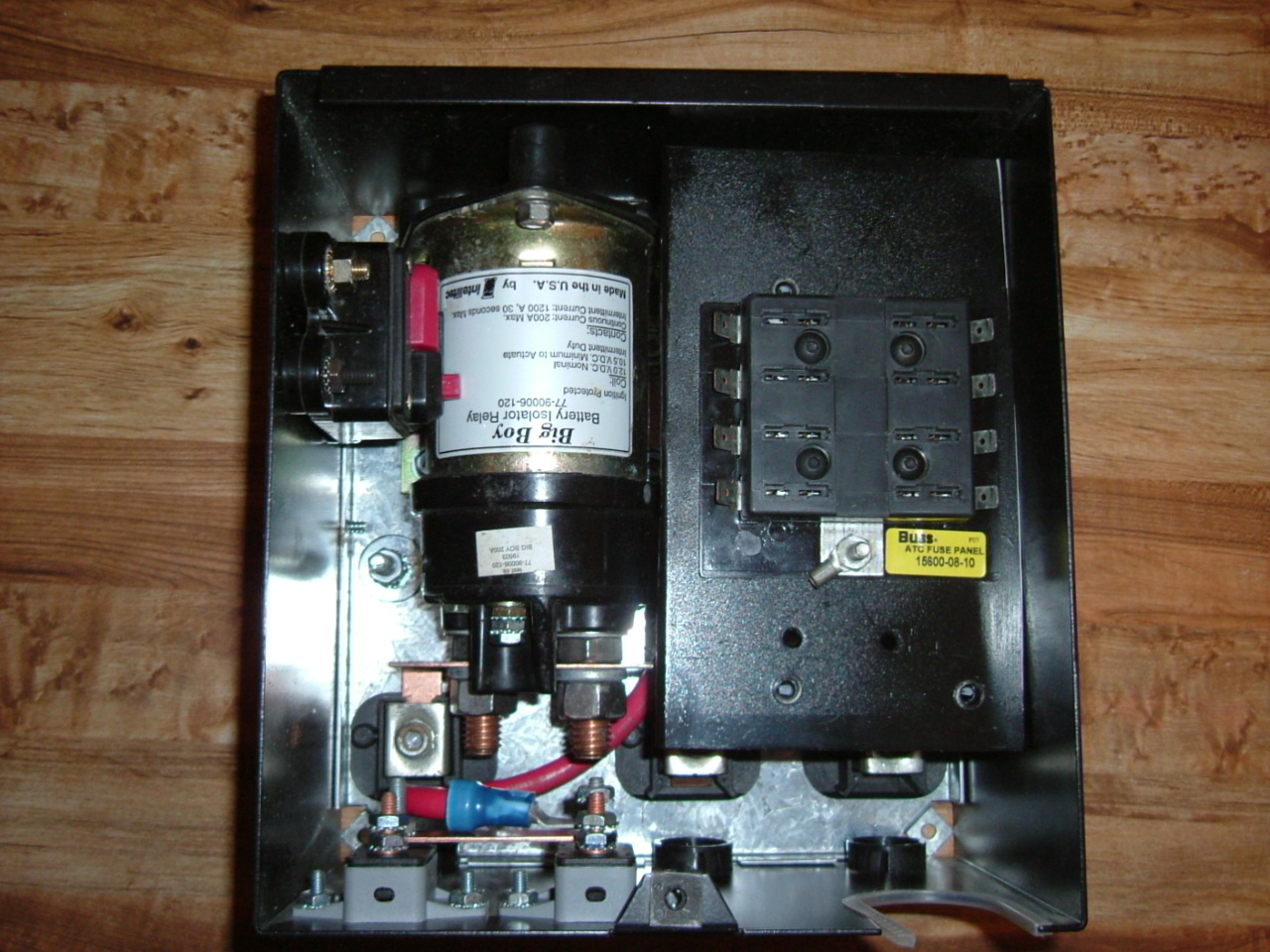
When I did my battery control center I started with one from a RV and built it from there. The fuses set on a platform above the starter solenoid.The big relay is the battery disconnect and the small solenoid is a Ford type starter solenoid. On the left wall is the main breaker from the alternator output. In the right lower corner is a connection point for the power lead to the starter. The connection points on either side of the big relay are the battery lead and the main power to the cars electrical system. There are 2 small (gray) 30 amp breakers on the end plate that I can pull power from if I need to.
When the battery disconnect relay is off the 8" lead to the battery is live. The line to the alternator with the breaker in it and and a 7 amp fused control circuit to the large relay are also live. Once the power is cut at the battery control center the engine does stop but the alternator out put still makes it to the battery. I have a inerta switch that also stops the battery power if there is a impact. A toggle switch is used to turn on/off the large battery disconnect relay or reset it if its shut off by the inertia switch.
All this sets next to the battery so there are not any large hot battery cables running to conventional disconnect switches.

-
I was considering installing a rollover/impact safty switch in the system to further improve safety. That way if I am out cold the electrical system will be too.
I have a bunch of the inertia switches used for fuel pump shut off. I set up my Z to use one but have yet to connect it. I actually have 2 setup, one for the pump and the other for the relay center so the pump is double covered.
If your in need of a inertia switch PM me and I will fix you up.
These switches use a steel ball suspended between 2 magnets with a red reset button. I have mine attached to the drivers kick panel so its easy to reset.
When I was researching the use of relays the one thing I read is early failure is caused by contact arcing when there is a heavy load on them when they are disconnected.
My main battery disconnect only cuts the power to the cars electrical system. I did not run the starter solenoid supply through it.
I have a 8" 2/0 positive cable from the battery that feeds a buss in the battery center, from there the starter solenoid feeds the starter and the main disconnects feeds the car. My alternator output does go to the buss. When everything is off I have a live 7 amp fused line to the disconnect relay switches and a 100 amp breaker in the live line to the alternator. these are in the battery center also.
I was going to do the relay and resistor for the for the alternator but figured if one or the other went out went out I could lose a alternator.
-
Thanks Dave,
The Constant duty solenoid and the small Bosch relays have them built in. The starter solenoid does not have a diode. I have some heavy duty 30V rectifier diodes I will install in several places when the small guage wiring is added.
I started out doing the battery disconnect center like yours but changed to a Intellitec latching relay for the battery disconnect instead of the continuous duty relay. The reason being that the continuous duty relay will always draw .75 amp to keep the battery connected. A latching relay only draws power momentarily to connect/disconnect the battery.
I have the battery disconnect center with fuses in the back of the Z like you are doing. In the disconnect center is also a Ford starter solenoid that supplies the starter power and starter solenoid power like I explained a couple posts back. I have a toggle switch mounted behind the rear licence plate that will disconnect the battery. All I do is remove the plate at the track to make it accessible. That is if I ever get there.
I also bought a Odyssey PC680 to use, but with its being only a 16 amp hour battery it will go dead in short order if anything is left on. I have a electric fan and water pump that will continue to run after the engine is shut down if the cooling temp is over 190 degrees. I have since switched a Exide equivalent to the Optima battery.
-
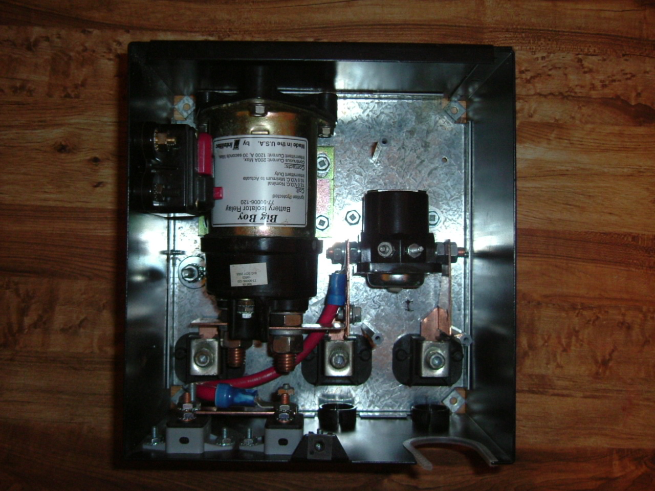
If you look at the solenoid/relay pictured you will see a diode between the (+) and (-) coil connections. This is a fly back diode also can be called a clamping diode. There is a inductive spike when the coil voltage is removed that causes arcing at the switch that runs the solenoid/relay and spikes into the cars electrical system. This diode takes the spike to ground. The switch points don't arc with the diode and it protects sensitive electronics in the car. Some relays come with clamping diodes but I don't think the ones your using have them.
-
Ha,
Another issue that crops up comes from the remote starter solenoid I am using to ensure that the 2g starter wire is dead except when it is starting the engine. I show a jumper between the starter BATT wire and the starter-mounted solenoid. This would work fine in a factory style starter. The problem comes from the fact that I am using a permanent magnet starter motor.
The permanent magnet motors can generate electricity if the pinion does not instantly/completely disengage. The electricy generated by the starter motor will energize the jumpered starter solenoid and KEEP the starter engaged until the engine overrunns it enough to kick the pinion off the ring gear. This is noisey and damaging to the starter.
The fix for this is to use the KEYED start signal wire to engage both the rear-remote solenoid AND the starter mounted solenoid(without a jumper). Unfortunately the starter signal wire is heavily taxed in the factory system. Forcing this wire to run TWO high current solenoids will not be smart.
The answer is to add another BOSCH 30A relay near the starter to take some of the load off the starter signal wire and get rid of the starter jumper in my diagram.
Remove that jumpered starter solenoid wire and use a Ford starter solenoid that has the 2 connections one being for the old point type ignitions. Use that (I) terminal that would normally bypass the ballast resistor in start position to trigger the solenoid on the starter. This way there is not a connection to let the starter run on as described above.
-
Seems like a neato piece of idea, I'd personally spend the money on other stuff, but sounds like it might work. I've sort of viewed batteries as a consumable, something to be replaced every x.
The one thing I am thinking is I have gone to a bunch of trouble to remove spikes and ripples from my electrical system and this just puts them back. It would be easy to connect this to a relay that will disconnect it when the ignition is on. If it will double the battery life as it says, it will pay for itself there.
-
Was doing some digging on causes of battery failure and what actually happens to the battery when its gone bad. I found a bunch of information about battery desulfation and how this can save a battery.
These guys http://www.batterylifesaver.com sell a device that connects to the battery and runs with out a external power source. It appears to have a capacitor and other circuitry that once the capacitor is charged up it spikes the battery with a pulse that over time disolves the sulfation or will prevent it from forming on a new battery.
I also found these guys http://www.wizbangplus.com that have one that is $35 shipped to your door and a few bucks less on eBay.
This device can in its self can draw a battery down over time so the car has to be driven or have a float charger connected if it sets for a extended period of time.
Any opinions?
-
I was wondering if anyone knows what the water temp sender and oil temp sender resistance values are in relation to temperature changes. I've searched and looked through pretty much every FSM but cannot find a chart like the one for the CHT.
My oil temp sender has gone bad, so I tried a water temp sender in its place in the oil pan. After idling the car for five minutes the oil temp reads
280deg! I was hoping instead of buying a new oil temp sender to just slip a resistor in the circuit to correct the value of the water temp sender to make the gauge read correctly, if there is such a thing as a stock gauge reading correctly!! Maybe someone has an oil temp sender they are not using?
Thanks in advanceAaron
Here is the information I found in the past on the water temp sender. These values are for the analog cluster not the digital.
23 C /73.4 F = 400 ohms
25 C/77 F = 386 - 365 ohms
30 C/86 F = 302 - 290 ohms
35 C/ 95 F = 238 - 228 ohms
40 C/104 F = 190 - 183 ohms
45 C/113 F = 153 - 149 ohms
50 C/122 F = 123 - 118 ohms
55 C /131 F = 98 - 95 ohms
60 C /140 F = 84.1 - 80.3 ohms
65 C/149 F = 69.0 - 67.2 ohms
70 C/158 F = 56.5 - 56.0 ohms
Here is what I found on the gauge.
Operating resistance range of the stock Z car temp gauge.
Cold - it's from 18K to 33K Ohms.
Hot - 250 - 400 Ohms
Hoped this helped, and post your results.
-
i could probabley grind the welds off in a minute. i just went out for a pointless drive just to feel it again. it was definatley worth it.
I had the same problem with hogged out holes in my mustache bar. My fix was to use large diameter plate washers instead of the 2 small ones that are pictured and stock. The large plate washers provide a much larger holding surface and are almost as thick as the mustache bar.
-
-
-
I was wondering if I should weld in a bung to run the PCV through the intake or just pop a filter on it and call it a day? Any reason not to?
I bought a Norgren filter/seperator off eBay for about $9 total new with mounting bracket and attached it to the firewall. Its all aluminum with a sight glass and drain cock. Ran the PCV line to it and from the filter/seperator to the manifold, it works well.
-
good luck Dan! i hope nothing happens to you, your family, or your possessions.
if hybridz goes down for whatever reason, ill be at classiczcars. seems like a good place to go since i think a lot of us are registered there already.
The site was down a short time ago but has come back.
We all have our fingers crossed and are praying all is well and stays well.
Classic Zcars would be a good place to go to for information if we go down again.
-
-
Hey guys, my 240 was rear ended and some parts are in worse shape than others. One that i am in need of I don't really know what to call, its the black part of the rear end that goes over the taillights and pretty much covers the whole back middle of the car. Is that the tailgate? If so does anyone know where i can get one...I have a bad feeling it's going to be a pain to find one. Thanks in advance.
I believe that part is called the tailight finisher, There are actually 3 pieces for the 240Z. Right, left and center where the license plate goes.
I also have all the pieces if you need them, just PM me.
-
The worst part about shooting home invaders is having to get out of bed to grab the shotgun. Well, that's no longer a problem with the The Back-Up Gun Rack, which provides a convenient and easy-to-install bed-mounted solution! Now you can fill invaders with two barrels of buckshot without even having to sit up!
A bed-mounted shotgun. What could go wrong?
http://www.the-backup.com/buy/commercial.php
The only possible way to improve this product would be to make it somehow hold beer.
-
Thank you, gentlemen.
I think the little automotive cube relays are generally rated at 20-30 amps; it should have been sufficient... live, and learn. I had a diode to catch the voltage spike, but didn't know the trick of adding a resistor equal to the coil resistance. Slow opening may have contributed to the relay's early demise.
Hopefully the 10 amps my VOM will handle is enough to measure the current draw; I'll see how hard it pegs the needle, and go from there.
Did you do the DC/DC SSR swap? I did the Honda cooling fan upgrade and burned up the fuse and fuse holder from the higher current draw of the Honda fan. I looked into the SSR's for the heater fan and the fuel pump and it looks like a better solution than the small automotive relay, and their silent.
I lost a couple relays for the radiator fan before I switched to a 80 amp continuous duty that looks like a Ford starter solenoid except it has a metal case. I am looking for something better than the standard relay but not as big as the ones I used on the cooling fan.
Are the SSR's rated as continuous duty? I did see some come attached to a heat sink.
-
Do you know if this would work?
Same one Harborfreight and $10 less!!
http://www.harborfreight.com/cpi/ctaf/displayitem.taf?Itemnumber=91772
If you have a Harborfreight in your area print the sale up and they will match it in the store.

Amp meter’s who runs them? What is the danger?
in Gen I & II Chevy V8 Tech Board
Posted
It may be safer, but there are problems with bad connections that will give you amp read errors or no reading at all from the 75's ammeter. At least the 75's ammeter will not burn up like the one in the 240Z can.