

jthom5147
-
Posts
146 -
Joined
-
Last visited
-
Days Won
1
Content Type
Profiles
Forums
Blogs
Events
Gallery
Downloads
Store
Posts posted by jthom5147
-
-
Anyone have any insightful on my edis wiring?
-
Zack,
Thank you also for looking, and that's a good suggestion. I've updated my schematic accordingly.

-
Mobythevan,
Thank you very much. I'm glad that it looks correct to you, especially with your credentials.
Much appreciation,
James
-
Hello readers,
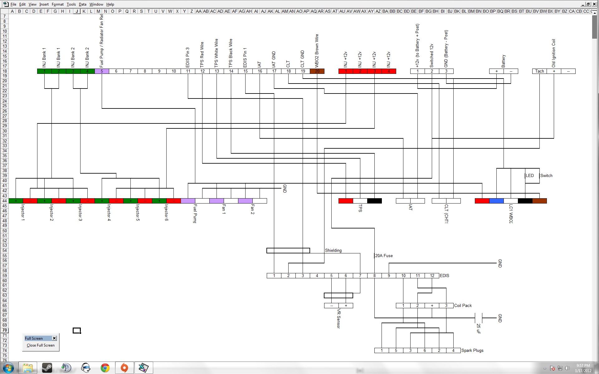
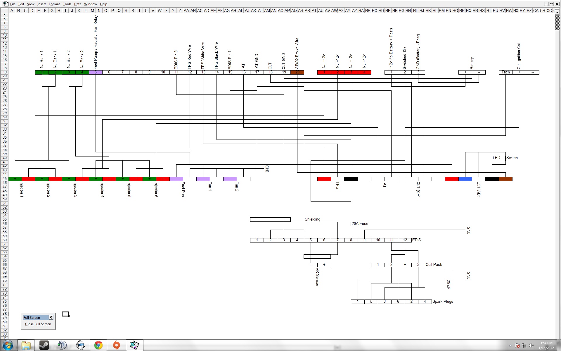
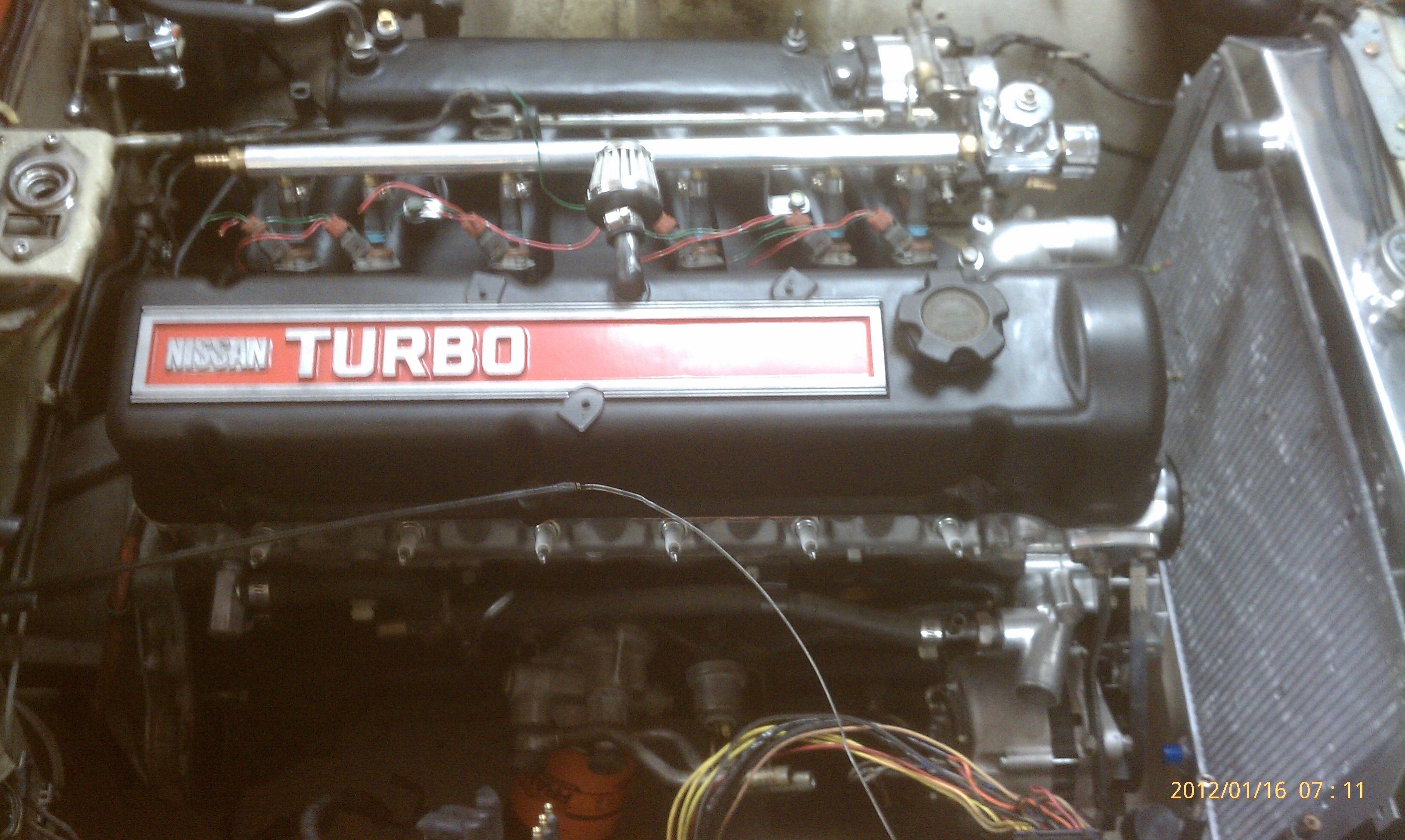
I've put my turbo engine in the car over the past weekend (pic attached) and I'm getting ready to wire the car, but before I start, I want to make sure my wiring diagram that I will be following is correct. I have been doing what seems like endless reading and research but the best way to make sure what I have is correct is review by the experts. If any of you can spare some time to review what I have, that would be absolutely amazing. I hate to be a nuisance.
Attached is a wiring diagram made in EXCEL. The diagram shows the wiring between the relay board and the car. The 4-hole socket for injector power, and the other 3-holes for relay board/MS power were rotated 90 degrees clockwise for simplicity. I tried to be detailed regarding where the wires go.
Things to note about the car:
1973 240z
MS2 V3.57 board
Relay board
l28et
stock 280cc injectors (I'll be using PWM controls for these instead of the resistor pack. As such, I will use the injector settings posted by Z-ya here: http://forums.hybridz.org/index.php/topic/55910-injector-opening-times-spread-sheet/)
stock t3 turbo
EDIS (using the edis-6 diagram posted on the MS website here: http://www.megamanual.com/ms2/EDIS.htm)
coil pack from a 2000 Dodge caravan 3.3L (mine has the plug type with the 4 spades in a row, so im using the info posted here by cygnusx1 as a reference: http://forums.hybridz.org/showpost.php?p=930882&postcount=18)
-- note on edis to ign coil pack wiring: since the L-series firing order is 153624, i wanted the edis module to fire the coils from one side to the other in order to clean up the spark plug wires. Since EDIS fires the coils attached to pins 10,11,12 on the edis module in the firing order 10->12->11->10.. etc, I needed pin 10 to connect to the coil pack for the cylinders that fire first and fourth in the Z firing order which is 1-6, then pin 12 needed to go to the next adjacent coil pack to fire cylinders 2-5, and lastly edis pin 11 to the remaining coil pack, and hence to the last 2 clyinders (3-4). Please let me know if this logic is fouled.
Innovate LC-1 (using the info in the quick start guide found here: http://www.innovatemotorsports.com/support/quickstart/LC-1_Quickstart.pdf and also from DIYautotune found here: http://www.diyautotune.com/faq/faq.htm#LC1wiring)
2 elec. radiator fans also wired into the fuel pump relay.
CLT sensor will use the CHTS (I'll have to calibrate it in MS using the values found here: http://forums.hybridz.org/index.php/topic/57800-280z-coolant-temp-sensor-values-for-easytherm/)
Please post any comments, concerns, errors, constructive/destructive criticisms, etc.
Thank you all very much for your time.
James
-
i was reading thisand that better illuminates my question. But that still leaves the question of what the visual differences are between the two types of studs.
And begs another question, what potential harm could come if my block still has the relief valve and the oil cooler installed?
-
Okay,
I started reading on here that the factory oil cooler adapter from 280zx turbo automatic cars has a different threaded stud and oil configuration than all other l-series engines.
I bought a built l28et engine with this factory oil cooler adapter installed. I don't wanna trash a good engine by not investigating and making sure that the adapter plate was properly installed.
I've read some other threads like this one l24 oil cooler convert. Maybe I'm dense but im having trouble understanding how to identify the difference between the two to double check my block.
I do not have a photo of my oil cooler adapter installed convenient. If one is required to help, I'll procure one. I can say that the block has the adapter attached and the banjo bolts are threaded into the adapter also.
What specifically is the difference between the two studs?
Is the ball valve supposed to be modified at all?
please help!
Thank you,
James
-
With the Nissan and the GM ones that I am familiar with, there is no polarity needed.
Thank you!
-
I guess I'm either overthinking or underthinking this. Since the sensor is in essence nothing more than a resistor that has variable ohm values depending on the temperature of the resistor itself. The MS will be reading the amperage for a given voltage across said resistor and then working it backwards with ohm's law to find the corresponding resistance value. MS will then find the corresponding temperature from the interpolated ohm to temp calibration graph with the derived resistance.
But, long story short, since the sensor is a resistor.... the resistance value should not deviate with direction of current flow but rather only with temperature change.
-
Hey everyone,
I'm working on my wiring diagram and making sure i know where to pull wires from / to. I will be using a relay board with MS2 v3.57.
Just for reference, IAT signal wires pair with positions 16 and 17 on the j20 terminal. CLT pairs with 18 and 19. 17 and 19 are the sensor return ground points.
My question is: do the stock turbo head temp sensor(which i would like to use as my coolant temp sensor) and/or GM open element IAT sensor have a polarity to the way the wires need to be hooked up.
Here is a link to the IAT i am using: IAT Sensor - DIYAutotune
I.e. does it matter which wire on the IAT goes to terminal 16 and which to 17? and which from the datsun head temp sensor goes to 18 and which to 19? or do they work the same way either direction of connection?
Thank you all for reading and perhaps helping!
-
AC yes ps no. I made this for my S30. We have to muscle our cars around but AC is a must. A larger diameter code wheel and different adaptor hub might allow for the ps pulley. I spaced it out away from the damper to avoid any possible feedback. In fact the stock fan won't quite clear. James said he will be using electric fans.
4 row alum radiator with alum shroud and dual electric fans!
The stock intake side and AC bracket bolts are unhindered by Tom's setup. I'm not so sure about the PS (none of the s30's i work on have had it installed).
-
As for their relationship in general, no, the mock-up depicted in the picture is not accurate. The missing tooth is "behind" the vr sensor in the pic. Since the rotation of the engine is clockwise the missing tooth needs to be 60 degree more clockwise than the vr sensor. I.e. if the crank pulley is a clock face, the vr sensor is at 12, missing tooth is at 2, so long as the engine is at TDC (or whatever number for the vr sensor you wish, and n+2 for the missing tooth).
-
-
Sent you a pm. Still looking.
-
That is very good info, thanks.
-
Hey guys,
I'm in the market for an OEM Non-EGR manifold. P82 is prefered, but N42 is fine also. It needs to be undamaged / in good condition. I will be shaving it down, so if it has already received some modifications (depending on what) that is ok.
It's going on my L28et to '73 swap.
Shoot me a PM or reply here.
Thanks,
James
-
Perfect, thank you Matt.
-
I very much appreciate the input. I hadn't ordered my ms board yet, so I went with a v3.57 instead of a v3.0 so that it is already setup for IAC.
Ideally, it sounds like something I want to have, but i will add it later after the engine is in and running (so I don't get distracted from my budget and time constraints)
Perhaps those of you that did use a stepper could find some time to take photos of what parts you used and how you setup the solenoid? Please?
Matt, do I need to make any modifications to the ms2 v3.57 (aside from the settings that come from your factory as default) board to wire in an stepper IAC? I'm using a relay board, so the stepper would use pins 6-10 on the J20 if my memory serves me right.
Thanks
-
Thanks. I'm doing this upgrade for my MS eventually and am a little confused on where the gap goes. DIY says 6 teeth ahead of the sensor, but does that mean 6 teeth before TDC?
In short, no.
The VR sensor and 36-1 crank trigger wheel must be set in the correct relationship to each other. With the engine at TDC for cylinder #1, this relationship is:
EDIS-4: missing tooth is exactly nine teeth (90°) ahead of the VR sensor,
EDIS-6: missing tooth is exactly six teeth (60°) ahead of the VR sensor,
EDIS-8: missing tooth is exactly five teeth (50°) ahead of the VR sensor.
Note that you have a choice where to place the sensor, IF you can shift the wheel. It is a good idea to build the VR sensor bracket so that you have a degree of radial adjustment (closer/farther from the wheel) and angular adjustment (closer/further from TDC). Also, bear in mind that most automotive engines rotate clockwise when viewed from the front, except many Honda engines.
Source: http://www.megamanual.com/ms2/EDIS.htm
The edis-6 needs the 60 degrees. The 60 degrees between the missing tooth and vr sensor can be positioned anywhere around the toothed wheel edge, so long as the 60 degrees are set in the correct relationship with the engine using engine TDC as a reference point.
I hope that is more clear.
-
It's just a mock up. Actually I sold the engine to a guy in CA. He is putting it in a nice '73 with MS so I imagine we will be hearing from him.
The engine is very clean as someone else said. I purchased some of the other components I know I will be needing for my swap and when I'm closer to starting work, I'll start a build thread.
Right now I'm also making sure I have an accurate and complete wiring diagram to follow.
--James
Any MS Gurus in Socal?
in MegaSquirt
Posted
School started for me, and so I lack the time to do my wiring and tuning myself. I'm taking the car to a shop in oceanside/Vista to have it done... The shop has done MS work before, so ill let you know the results when I get the car back.