Bob_D
-
Posts
34 -
Joined
-
Last visited
Content Type
Profiles
Forums
Blogs
Events
Gallery
Downloads
Store
Everything posted by Bob_D
-
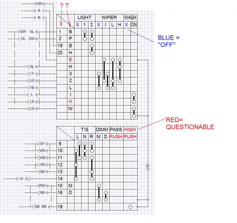
Hi Dom, thanks for the reply. I agree that the numbers could relate to connectors, but in looking at the connectors on the turn signal/high beam switch even using a magnifying glass, I don't see any numbers on the connectors themselves. Besides, some of those numbers are associated with a wire that just has a single "bullet" style connector and isn't part of a larger multi-pin connector. Still, perhaps it relates to the other end... those 10-pin connectors in the passenger area? As far as the letters go... E=earth makes sense since this is a black wire. I'm really stumped on the M and D on the turn signal/high beam switch. And if anyone can correct or confirm the HIGH PUSH PUSH in red in the jpeg That would be a big help.
-
I've done quite a bit of searching, but have not come up with an answer to this... I have a 73 240, I have the factory service manual, as well as the downloadable version that someone was nice enough to post on a different site. Here's my questions: The FSM wiring diagram for a car with a manual transmission (page BE-5) shows Fog Lamps, which I understand was not a U.S. option, so I am not surprised to find no wiring for them in my car, but the diagram also shows "step lamps" (right and left hand), which I can't find any evidence of my car having. I am assuming that these were not a U.S. thing either. I am wondering what else this wiring diagram is showing me that does not exist on a US spec car. Does anyone have any insight on this? Here's another thing, I am trying to decipher what the diagram is showing me for the combo switch/turn signal switch. My manual is a little blurry on some parts of that "chart". I have redrawn it (see attached graphic) with the questionable bits in red, and I put blue X in place of the word "off" (since the word was too long to fit in my graphic). Also, does anyone have any idea what the numbers in the left column are for. I'm thinking the letters in the second-to-the-left column must relate to things like H=high, L=low, I-intermittent, etc. but some of those letters are not making sense to me. With all the electrical topics discussed on this site I'm kind of surprised that there isn't a dedicated electrical section!

-
Well the new regulator looked just like the one that didn't work, so I got my money back and will try a different parts house. A buddy of mine who put a SBC in his 240 says he has his original VR in the parts box somewhere in his garage and will try and locate it for me. I also went through the box of old parts that the previous owner gave me when I got this car, and there was an old relay style regulator in it! The cover is riveted on, so I will drill out those rivets this weekend and take a peek inside. I don't think it was OE, as there are no identifying markings anywhere on it except a "Made in the USA" ink stamp. Also, very odd, but the white wire is cut and just hanging, and this does not corespond to the missing "L" wire in the chassis wire harness connector.
-
Update: My RockAuto alternator tested out OK at O'Reilly's. Napa acknowledged that the part they gave me didn't match what was ordered, so another one is on order, should be in Tuesday-Wednesday. I found another blown fuse, 3rd down on left side, 20A labeled "IGN" and "Flasher". Replaced that and my gauges started working again! I will update again when the new, hopefully correct, hopefully solid state voltage regulator arrives.
-
Hi NewZed, thanks for the hyperlinks. I have been eyeing the internally regulated conversion for a while and it's on my "someday" list. I really wanted to spend my money on more pressing items first, like new bushings in the suspension (mine are still original, and you can definately feel it on the freeway). But it looks like I may have to rearrange my priorities. The new alternator I got frfom RockAuto was a $20 closeout special, so I was hoping to get it working. Oh well...
-
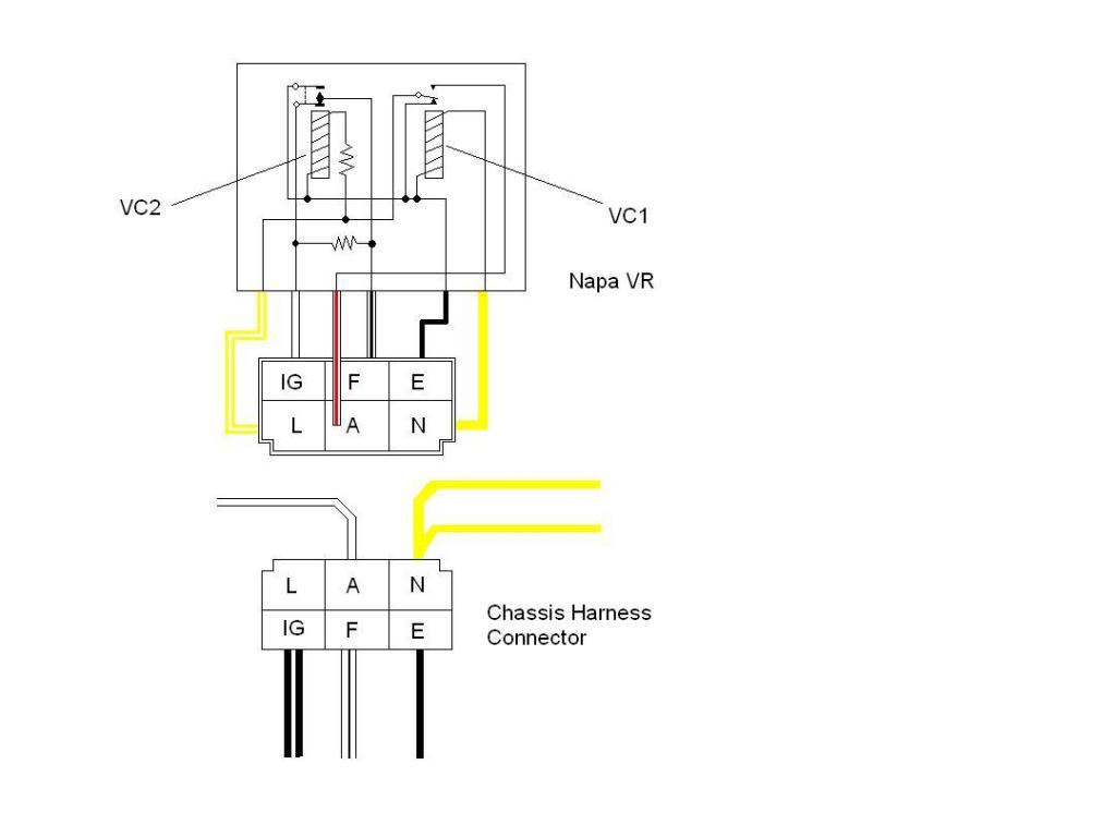
Last night I took the cover off the new VR and drew out the schematic using my DMM to confirm continuity. I have come to the conclusion that Napa must have sold me an incorrect VR (the box was right, but the contents, not so). I have attached my schematic, along with what the FSM shows on page EE-12, and as you can see, they don't come anywhere close to matching up. One obvious thing is that the FSM shows 3 resistors, the Napa part has 2, but even more concerning to me is that the E connector (black wire) connects to all sorts of things in the Napa VR that the FSM does not show as being connected. I will return/exchange the VR later today and see how that goes. Hopefully I didn't fry my new alternator by using this VR. (I think I will pull it and have it tested just to be safe.) I have a question for all you 240 electrical experts out there... the FSM on pages EE11 and EE12 talks about how the VR functions, and it specifically mentions a warning lamp. The schematic on EE12 even shows the lamp, and it's being connected to terminal L. However, the body schematic on page BE5 does not show a warning lamp, and in fact shows that the L terminal on the VR is unconnected. My chassis harness has no wire to the L terminal (and it looks to be unmolested original equipment), so I am inclined to believe that page BE5 is correct, and page EE12 is incorrect. (Also, I don't see any sort of alternator warning lamp anywhere on the dash.) So, for you electrical geniuses out there, how trustworthy is the FSM schematic shown on EE12 in regards to the factory VR? Can I safely ignore the lamp portion of that schematic and trust that the rest is accurate? Thanks in advance.
-
Well I've managed to make things worse. Now none of my gauges are functioning. I found the upper left fuse was blown (marked Air ConD, 20Amp, but I don't have air conditioning) I replaced that, still no gauges. I noticed that the light behind the vent controls comes on when I turn the key on. I've never seen this before (or at least never noticed it before), and this is with the headlights off. I've checked continuity from the alternator to the VR plug, and all those wires show good continuity. The battery is reading 12.58 volts with the engine off or running with the old solid state VR. NewZed: My Napa VR does not have any markings where the wires are solderd to their respective locations. That sure would have made it easy. TheBruce: Thank you for getting me the picture and diagram, I appreciate the effort. Your VR looks very different from mine, so I am thinking like you, "apples and oranges". It's getting too dark out in the garage for me to work any further today, but I really appreciate the suggestions you guys have given me. Please keep them coming! (Especially if you have any ideas why my gaiges quit working and how can I fix that!)
-
Hi NewZed, thanks for responding. My chassis harness looks original and unmolested where the voltage regulator plugs in, and according to the FSM (page BE-2, item 7), 5 wires to the connector are correct (no connection at "L"). I had considered that perhaps the battery was severely undercharged and was getting tons of current to help make up for that, but it was getting so much charge that electrolyte was leaking out from the inspection caps! Also, the battery is only a year old, and like I said in my first post I do keep it on a float charger during the week, and after 15 minutes of driving it around the Amp gauge still reads almost to the full + side and shows no sign of coming down. Being suspicious that perhaps my "budget" float charger wasn't actually keeping my battery topped off, I hooked up the battery to a regular charger. It showed that my battery has a full charge. So I am really suspicious of my new voltage regulator being mis-wired. Since I don't have an original equipment VR to compare against I don't have a way to confirm my suspicions, and my chief clue is because the new VR wiring does not match what is in the FSM (page EE-24), which details wire colors and locations that differ from my new VR. I am reluctant to just re-wire my new VR connector without getting some confirmation from a fellow Z owner that mine is incorrect. (My #1 suspicion is the white wire with red stripe being in the wrong position on the connector of the VR.) I am attaching a sketch of the backside of my new VR, can you confirm if it looks like yours? Thanks!
-
HELP! I suspect I have a bad voltage regulator, but have no good baseline to look at. Here's the problem: I got my 240Z (build date 9/73) over a year ago, and it was pretty obvious out of the box that the charging system was not working (Amp gauge shows discharge with lights and blinkers, but never goes to the + side). Since this has been a "plaything" for weekends I've been getting by with a trickle charger during the week to keep my battery topped off, and kept to daytime around-town driving on the weekends. I recently got a 60Amp alternator from Rock Auto (it came with a sticker claiming it was EXTERNALY REGULATED), and I purchased a new VR from NAPA. I put these items into my car and the AMP gauge will almost peg on the positive side when the RPM's are above 2500. Even at idle it is slightly to the + side. The old VR was a solid state unit but my new one is a traditional mechanical style. My confusion comes when looking at the wiring of the two voltage regulators, as the colors of the wires are not all in the same spot on the connector. Also, the wiring harness in the car only has 5 wires going to the rectangular 6 wire plug, but both voltage regulators have 6 conductors going to the plug. See the attached sketch to understand why I am confused. The new VR wiring colors do not match the old one, and neither seems to match the wiring harness in the car. All these sketches are from the viewpoint of looking into the connector. When connected the solid black wires do match up with each other. On the wiring harness sketch I noted some wire colors in parenthasis, this is because I can't quite tell if the original color was white or yellow. I put my best guess down first, with an alternate color in parens, like this: White (Yellow?). Also, when two colors are noted, the second color is the stripe color, so White/Red means a white wire with a red stripe. I know that the original "from the factory" voltage regulator was of the mechnical type, and this solid state regulator was an aftermarket part. Is my new voltage regulator mis-wired? EDIT: Putting in the older solid state VR resulted in a no charge condition with the new alternator.