
74_5.0L_Z
-
Posts
1161 -
Joined
-
Last visited
-
Days Won
10
Content Type
Profiles
Forums
Blogs
Events
Gallery
Downloads
Store
Posts posted by 74_5.0L_Z
-
-
Looks good. Except for the two picture that look like neck X-Rays.
What is the side to side distance between your LCA mounting holes?
How Long is the slot?
-
I am ready for others to enter the discussion. Specifically, if you have dimensions of components or chassis points, please post them here.
We can begin to use the tool to compare suspension geometry modifications.
-
Before I distribute this to the whole community, I would like to test drive it with some of the senior members.
Specifically, I would like to give copies of the Suspension Analysis tool to Jon Mortensen, Cary McCallister, John Coffee, and other with significant suspension experience or with knowledge of the stock S30 geometry. If you guys could PM me with email addresses, then I will send you a copy.
I am ready for other to enter the discussion. Specifically, if you have dimensions of components or chassis points, please post them here.
-
Discussion of Math Model in images below.
If you are an engineer, a math geek, or a glutton for punishment, feel free to read the discussion below.
If you only care about the end result start at page 9 and 10 to skip the math.

The only way I could present the discussion of the analysis was using images of my analysis in word.
-
Steering Rack
The critical dimension of the steering rack is the spacing between the centers of the inner ball joints. The measured spacing of the stock S30 rack is 24.25 inches center to center.
The rack is placed via the cross member such that its center line runs parallel to the chassis Y axis of the base coordinate system. When the steering wheel is centered and the wheels are straight ahead, the centers of the inner tie rods (in my car) are located such the right inner tie rod is located at (80.75, -12.13, 3.12), and the left inner tie rod center is located at (80.75, 12.13, 3.12). When the steering wheel is turned clockwise, the right side of the rack extends, and the left side retracts from the rack housing. The rack can extend a total 2.39 inches in each direction. So, when the steering wheel is turned all the way to the right the center of the right inner tie rod ends is located at (80.75, -14.52, 3.12), and the left at (80.75, 9.74, 3.12).
-
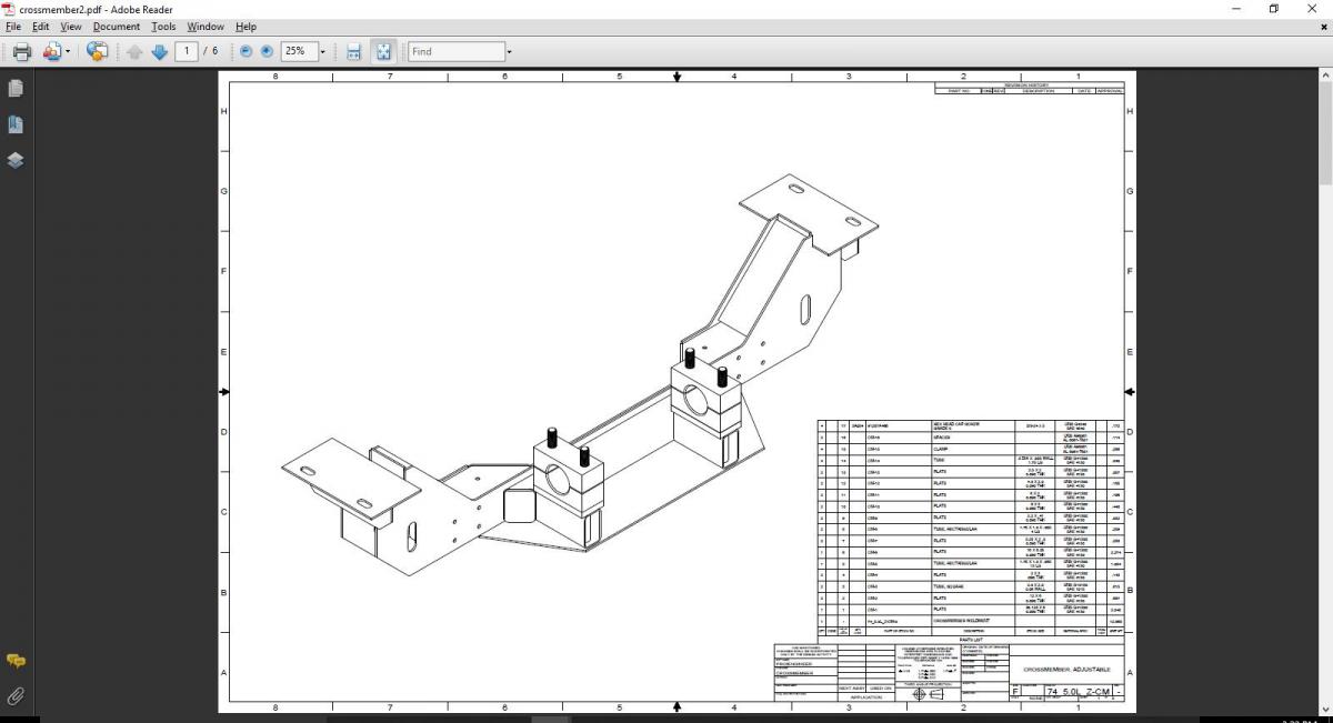
Front Cross member
The factory drawing does not provide the dimensions of the front cross member nor does it give the coordinates of the attach points between the frame and the cross member.
On my car the entire front frame has been recreated using tubing, but I used the FSM dimensions as a general guide. The height and spacing of my frame rails are the same as stock. They are 25.1 inches apart and the bottom surface of the frame rails are 5.12 inches above the base coordinate system. The attach points between the frame and my cross member (which are not stock) are as follows: The front mounting hole is 23.625 inches forward of the firewall and 15.063 inches from the car's centerline. The rear hole is 3.5 inches aft of the front hole.
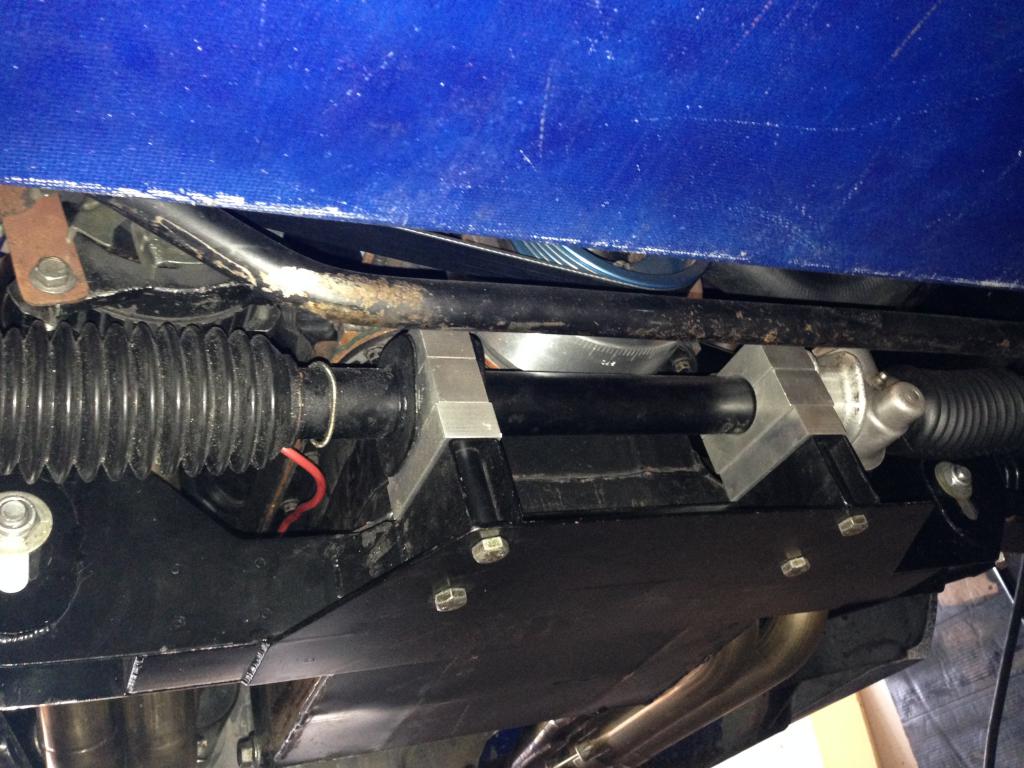
When I was measuring all of this stuff to try and get a handle on my geometry, I found that the old cross member was pretty distorted from years of abuse and several cycle of modification, so I decided to make my own to allow me to easily change the LCA mount height and to easily change the mounting position of the steering rack.
The cross member moves the attach point of the LCA forward, but leaves the rack in its original fore and aft location. The rack height is adjustable by changing the thickness of the spacers below the clamps around the rack.
The slot is located 12.13" from the centerline of the car and allows the height to be adjusted from 1.21 " to 2.21 inches above the base coordinate system. The height of the LCA attach point is adjustable in a slot that accepts Allstar Performance Caster slugs. Currently, the LCA is as high as the slot allows.
The table below give the locations of the LCA hole in the stock cross member, the JTR modified cross member, and my cross member.
Table 2: Position of LCA Attach Point relative to Base Coordinate System.
My Cross Member Stock Cross Member JTR Modified Crossmember
Point Description X Y Z X Y Z X Y Z
LCAR Center of Right LCA attachment to Cross-member 77.2 -12.13 2.12 TBD -11.625 1.56 TBD -11.875 2.31 -
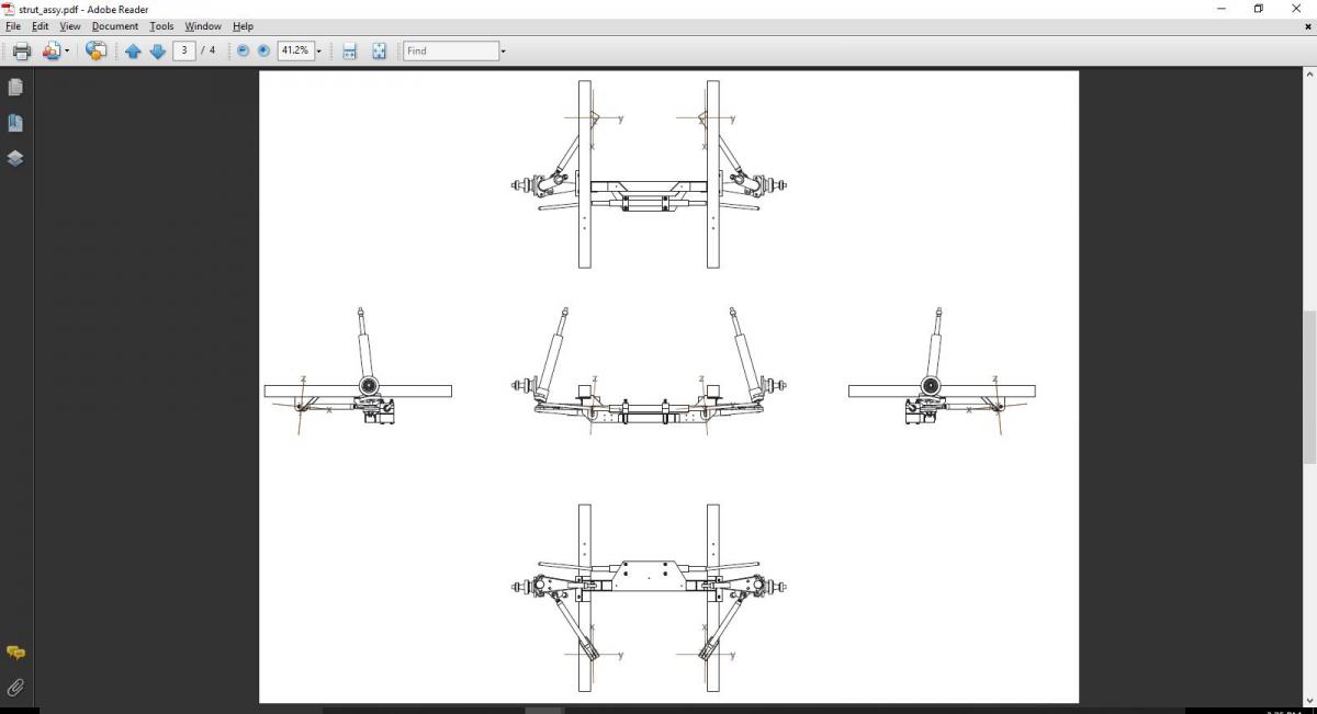
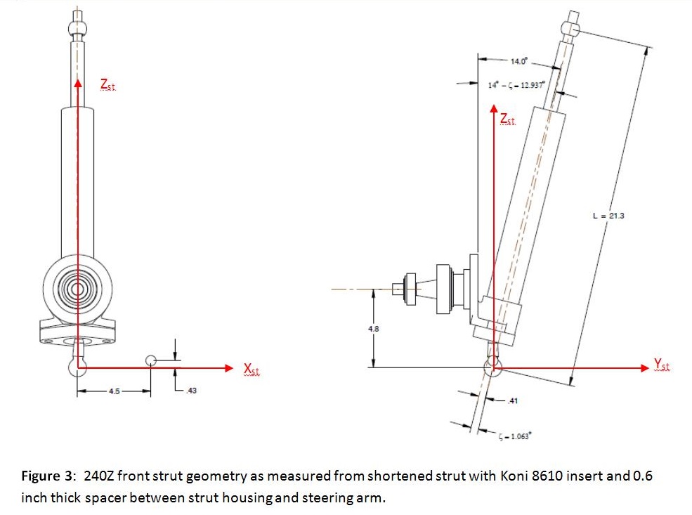
Strut Assembly:
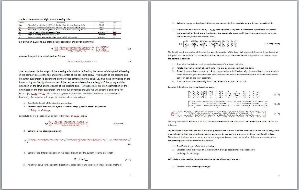
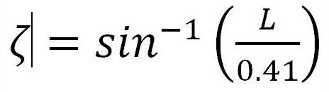
The front strut assembly has a 14 degree angle between the machined surface normal to the spindle and the axis of the strut tube. The lower ball joint is connected to the strut tube through the steering arm that bolts to the bottom of the strut. The placement of the center of the ball joint is located on the centerline of the strut tube as seen in the view normal to the spindle axis (left view in Figure 3). However, the center of the ball joint is offset inboard from the centerline of the strut tube by 0.41 inches as seen in the right view in Figure 2. The offset of the ball joint center causes the angle between the steering axis and the strut tube axis to vary with the length of the steering axis. The relationship between the steering axis length and the angle zeta is governed by the following equation:
The length L in the equation is the length of the steering axis. The dimension shown (21.3 inches) is the value for my suspension at ride height.
The coordinate system that is attached to the strut assembly is located at the lower ball joint center with its Y axis parallel to the spindle, its Z axis is upward in the plane containing the center of the camber plate spherical bearing and the ball joint, and the X-axis is forward. Relative to the strut coordinate system, the center of the outer tie rod on a stock right front steering arm has the following coordinates (4.5”, 0.0”, 0.433”).
-
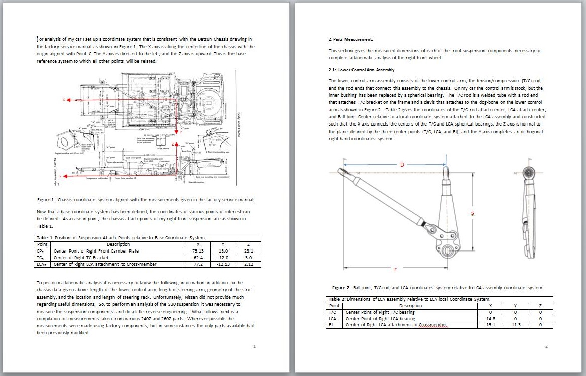
Lower Control Arm Assembly
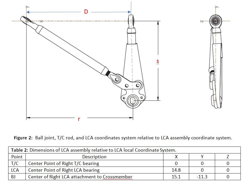
The lower control arm assembly consists of the lower control arm, the tension/compression (T/C) rod, and the rod ends that connect this assembly to the chassis. On my car the control arm is stock, but the inner bushing has been replaced by a spherical bearing. The T/C rod is a welded tube with a rod end that attaches to the T/C bracket on the frame and a clevis that attaches to the dog-bone on the lower control arm as shown in Figure 2.
Table 2 gives the coordinates of the T/C rod attach center, LCA attach center, and Ball Joint Center relative to a local coordinate system attached to the LCA assembly and constructed such that the X axis connects the centers of the T/C and LCA spherical bearings, the Z axis is normal to the plane defined by the three center points (T/C, LCA, and BJ), and the Y axis completes an orthogonal right hand coordinates system.
-
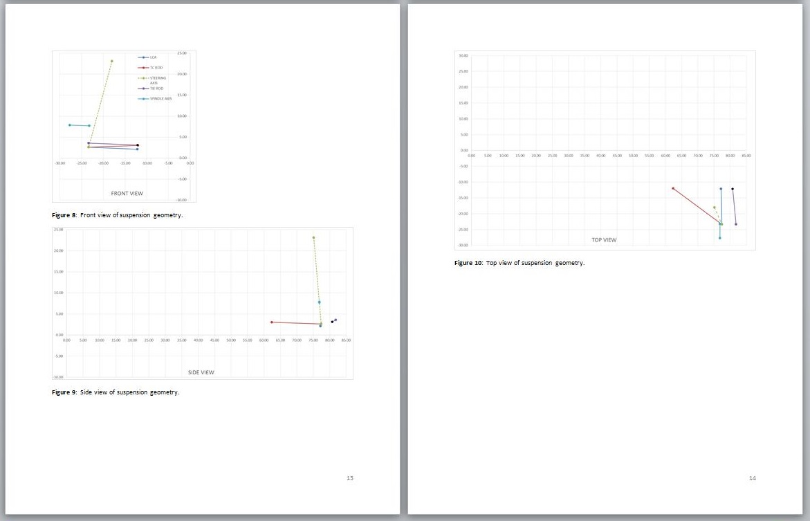
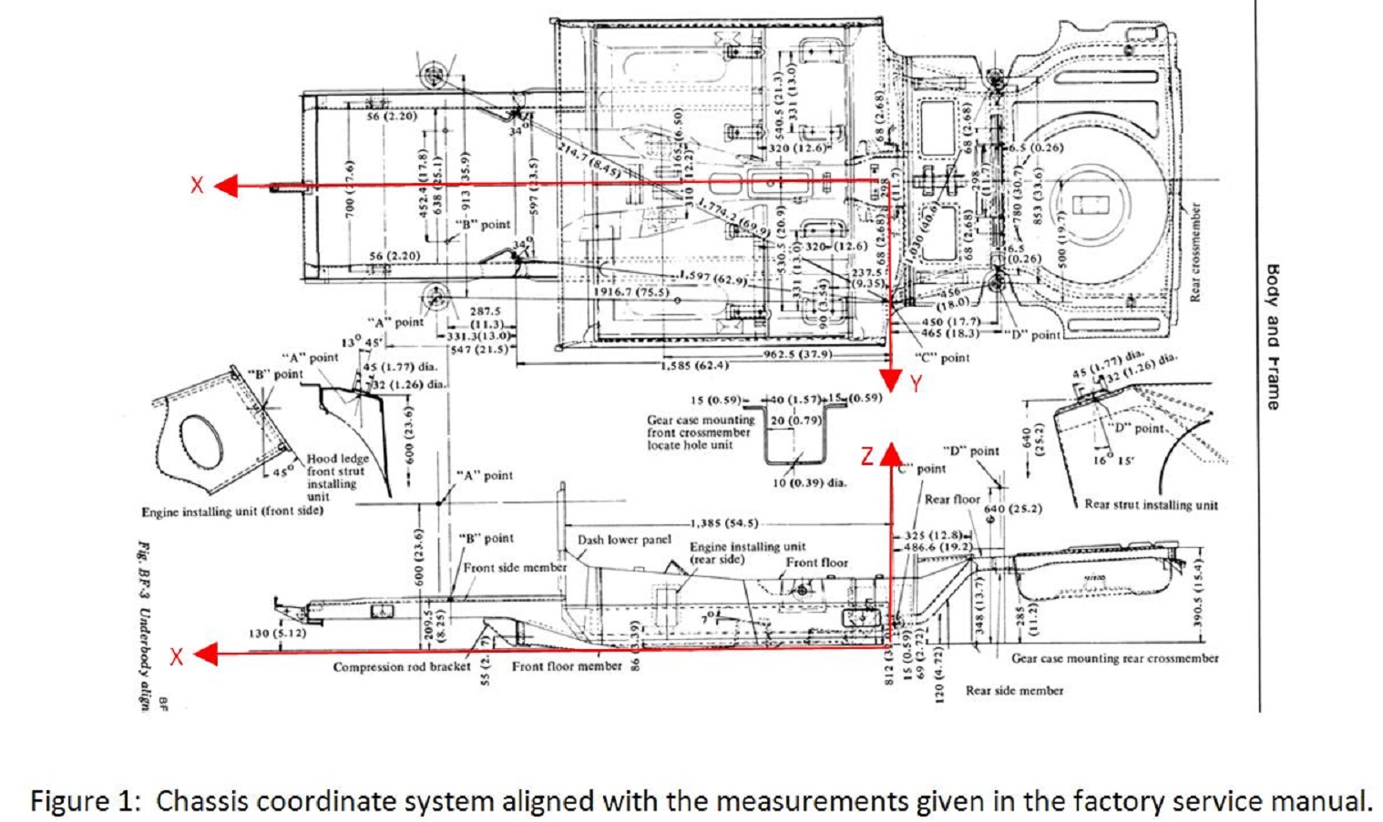
For analysis of my car I set up a coordinate system that is consistent with the Datsun Chassis drawing in the factory service manual as shown in Figure 1. The X axis is along the centerline of the chassis with the origin aligned with Point C. The Y axis is directed to the left, and the Z axis is upward. This is the base reference system to which all other points will be related.
Now that a base coordinate system has been defined, the coordinates of various points of interest can be defined.
Based on the coordinate system established above, the chassis attach points of my right front suspension and the stock front suspension are as shown in Table 1.
Table 1: Position of Suspension Attach Points relative to Base Coordinate System.
My Suspension Stock Suspension
Point Description X Y Z X Y Z
CPR Center Point of Right Front Camber Plate 75.13 -18.00 23.1 75.4 -17.9 23.1
TCR Center of Right TC Bracket 62.4 -12.00 3.0 62.4 -11.75 2.17
LCAR Center of Right LCA attachment to Cross-member 77.2 -12.13 2.12 TBD TBD TBDTo perform a kinematic analysis it is necessary to know the following information in addition to the chassis data given above:
Length of the lower control arm, length of steering arm, geometry of the strut assembly, and the location and length of steering rack. Unfortunately, Nissan did not provide much regarding useful dimensions. So, to perform an analysis of the S30 suspension it was necessary to measure the suspension components and do a little reverse engineering. What follows next is a compilation of measurements taken from various 240Z and 260Z parts. Wherever possible the measurements were made using factory components, but in some instances the only parts available had been previously modified.
-
This is the start of an analysis of the front suspension on my car. It has been modified several times, so most of the dimension are different than those of a stock S30. However, as part of this discussion I want to establish the geometry of the factory suspension so that we can compare various modifications and determine whether an improvement exists.
During this discussion, I plan to present the geometry of my suspension and discuss how I arrived at those published dimensions. I also plan to discuss the mathematical model of the suspension, and finally to make the model available to those who need it.
All I ask is that people refrain from posting until I have finished the initial part of the discussion. I will post several installments before I open the floor for discussion. Until that time, feel free to PM me with questions / comments.
-
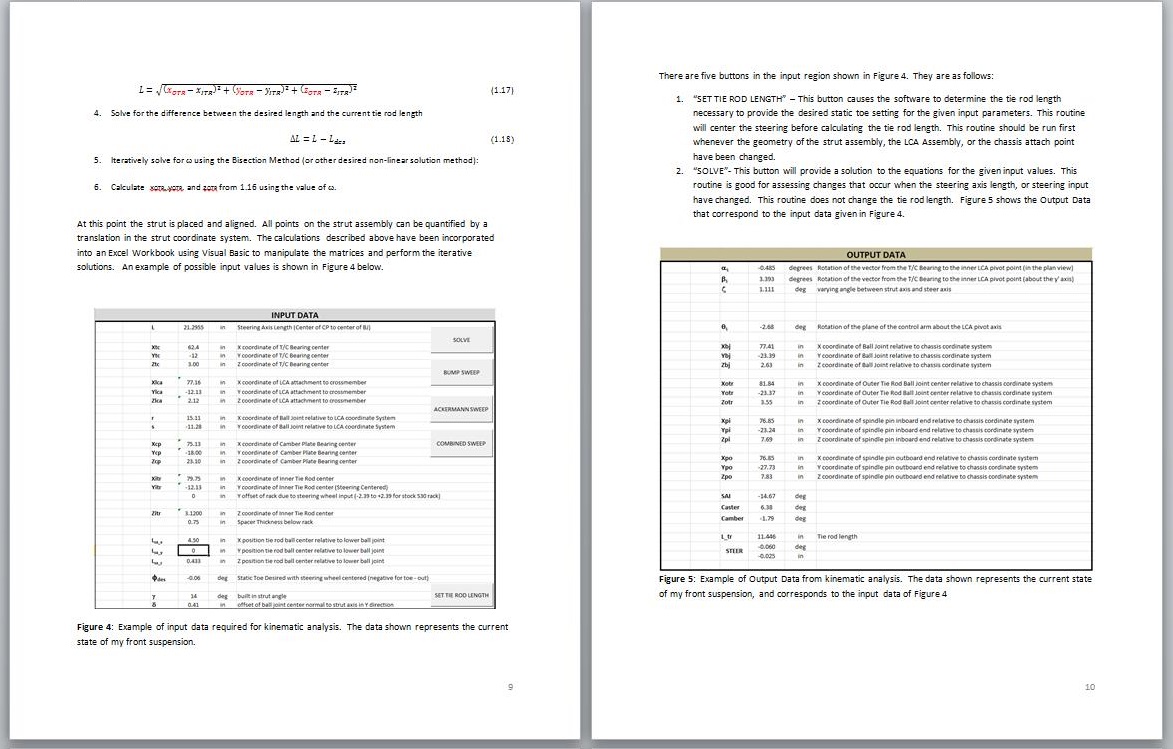
Actually, I have been doing a little deeper digging into suspension geometry lately and have discovered that I was not completely correct in some things. To explore the suspension geometry questions that I have had and that have arisen here lately, I created an accurate 3D kinematic model of my car's front suspension (in Pro/Engineer) which I could move and measure things like camber, caster, toe. The model was great, but making geometry changes was time consuming. So, when I was satisfied that I had an accurate model, I wrote a program using Visual Basic within Excel that given the same input as the Pro/engineer model gave the same output (camber, caster, toe). The nice thing about the program as opposed to the model is that I can change the geometry very quickly and see the results.
The most difficult part was not making the Pro/engineer model nor was it writing the program, but was getting accurate dimensions of all the necessary components that make up the suspension. To model the kinematics accurately, you need to know the center of the attach points of the LCA, T/C rod, strut top, and inner tie rod relative to the chassis. You also need accurate geometry for the LCA assembly (which consists of the LCA, TC rod and ball joint), accurate geometry for the strut assembly (which includes the steering arm, spindle, strut insert, and spring), and accurate geometry for the rack and pinion.
I have spent considerable time lately doing my best to quantify all of this, and I have been trying to find the time to post the measured geometry and the derivation of the model. I have spent hours cutting apart ball joints and disassembling steering racks and measuring all sorts of parts.
I also plan to freely distribute the Excel Program to those who want it. Within the next couple of days I will begin a thread with my results. What I will ask in return is that those who have better measurements to provide them.
-
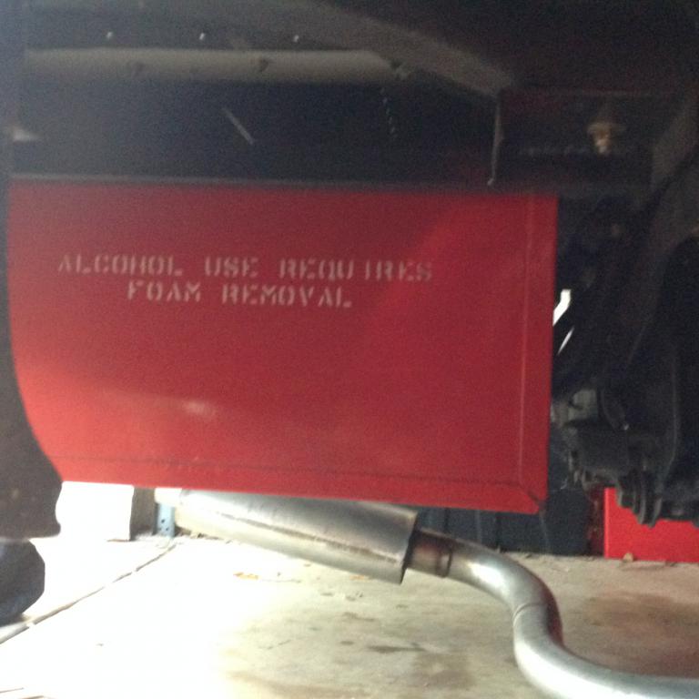
Yeah, If mine was a street driven car, the fuel cell would not be fun.
-
The type of fuel cell that you removed are terrible for fuel delivery. What you have created should work much better, but you could have achieved similar results with off the shelf parts.
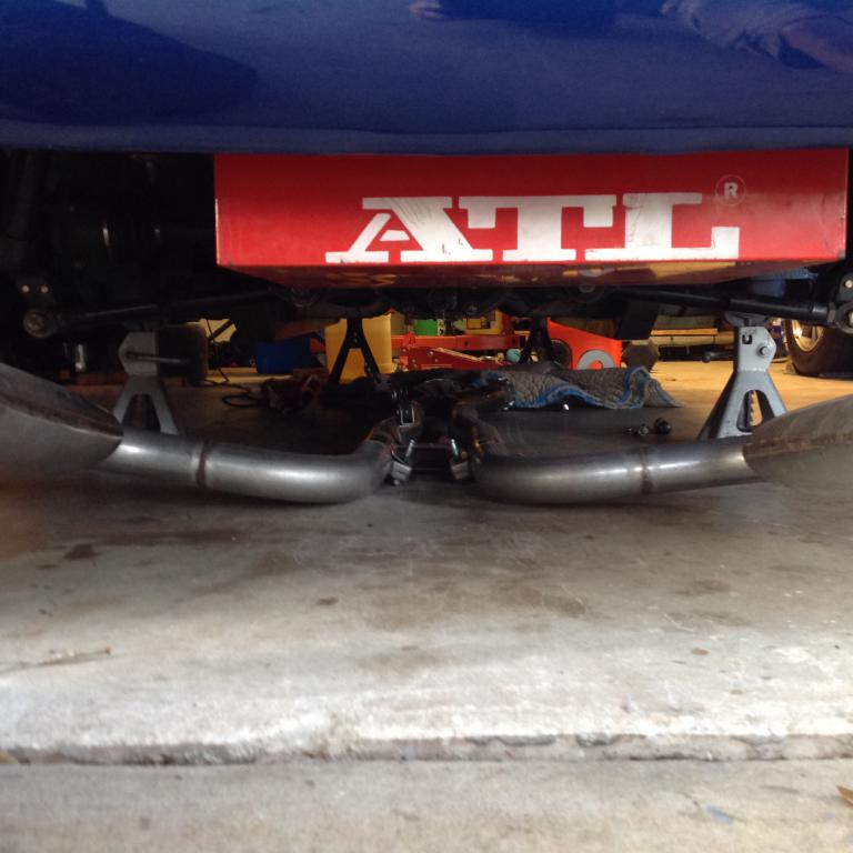
A real fuel cell (ATL or Fuel Safe) can provide consistent fuel pressure under all conditions even when the fuel level gets really low. I have an ATL SP112 cell with the ATL Black Box fuel pump and sump installed. The cell is 12 gallons and is mounted below the rear deck.
The only real downside is that without a fuel sender, you do not know when you are low on fuel.
I ran an event last weekend and made five full autocross runs with out starvation. Today I started the car in the garage and ran out of gas at idle.
The only use of gas from the last run until today was loading and unloading from the trailer.
-
Those will be way too tall. Look at the Hoosier 23.0x9.5-15 or the Avon 23.0x10.5-15. About the tallest tire you can hope to fit on a non-lower 240Z is about 24.5 to 25 inches tall.
-
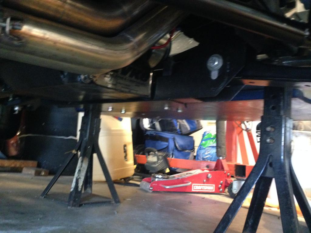
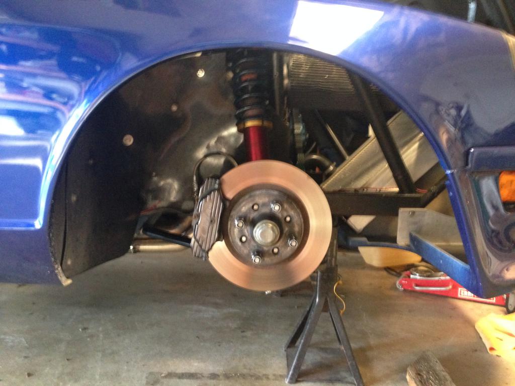
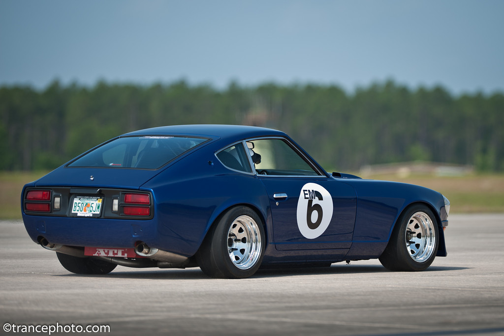
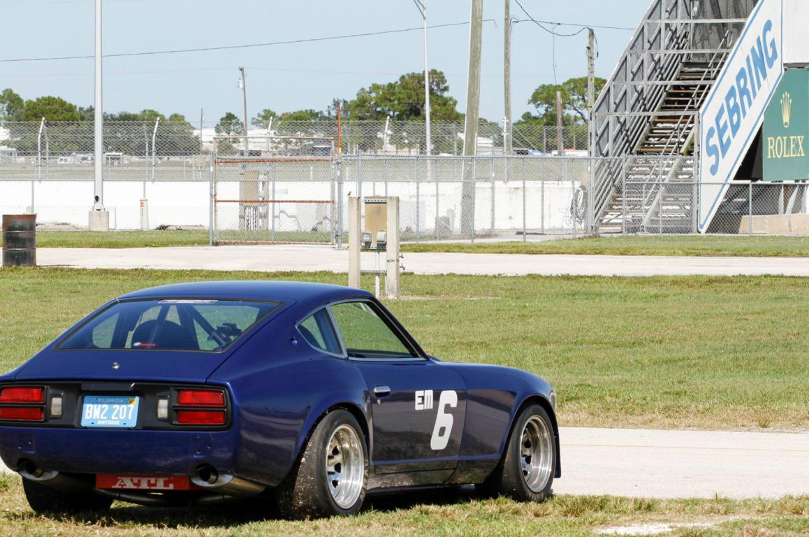
I haven't shown my rear end in a while, so here you go:
-
What size wheels do you need to be able to run those?
-
Cool. I didn't have dial indicators laying around, and I stumbled upon my bump steer set-up on ebay for $75.00. It is essentially two dial indicators, an adjustable base, and a graduated plate that mounts on the hub.
-
I am not sure how you would measure bump steer with just two dial indicators.
What are they attached to for a stable reference, and how do you track wheel height displacement from nominal ride height?
-
I have the InterComp Bump Steer Gage. I had to buy the four hole plate separately.
When you bump steer the car, you need to do a few things to get accurate repeatable results.
1. Get the car on a nice level surface.
2. Center the steering. For this I have made two equal length (2.39") spacers that fit over the rack shaft under the boots that force the rack to its center position.
3. Find ride height on the strut shaft. For this I push the bump stop against the strut housing, lower the car, roll it back and forth, and then raise the car and measure the displacement of the bump stop.
4. Remove the springs and disconnect the sway bay.
5. Follow the instructions in the bump steer gage. Take measurements at 1/2" increments of bump and droop starting from ride height.
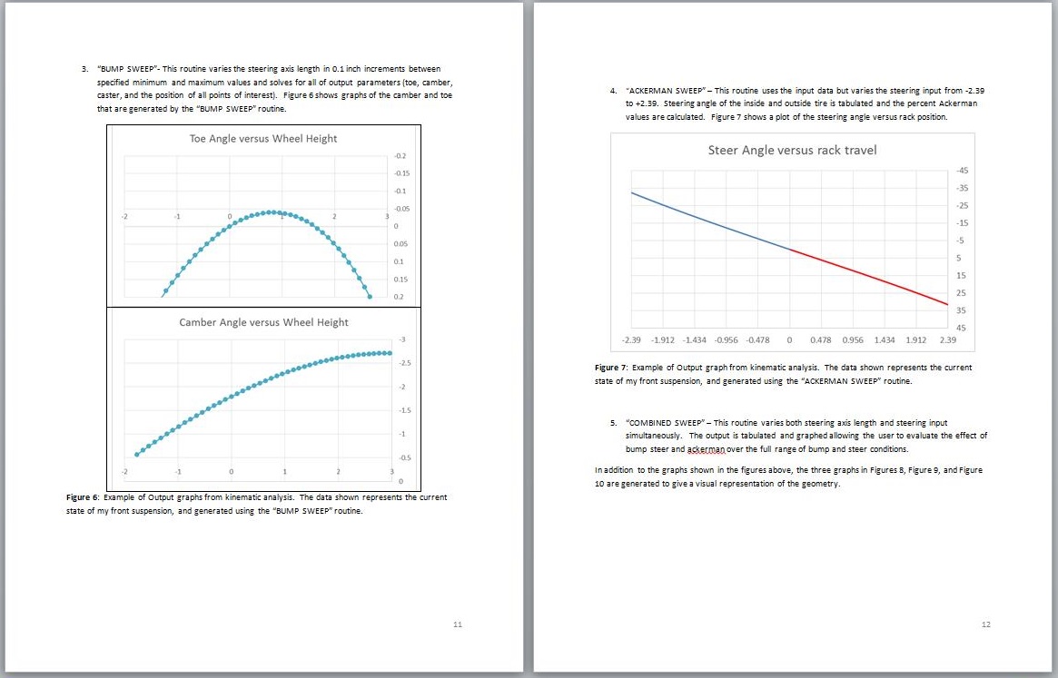
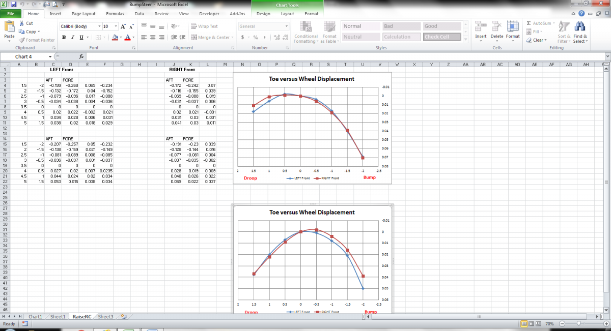
You want to perform the bump steer measurement on both sides of the car. If the measurements from the two sides are significantly different, then the cross member may be shifted left or right, or the rack may not be square with the car. Attached below are two different rounds of bump steer measurement for my car. The top set was a baseline after I raised by LCA attach points 1/2". For that initial measurement, I used a stack of spacers to raise the rack .39 inches. From the curves, I had not raised the rack enough because bump was causing toe in. So, I made thicker spacers that raised the rack an additional .050". The second set of data shows that I shifted the bump steer curve slightly to the right and up. So, for at least the first 1/2" of bump, the tires bump out. My car has 500 lbf/in front springs, so I do not expect to get very much deflection over typical road bumps. If I raised the rack further, I would shift the curve farther to the right and farther up.
As an aside, I am not really happy with these results. My next action will be to verify that a shorter rack will help the bump steer. My calculations indicate that a rack about 2.25" shorter center to center will virtually eliminate bump steer. To test this I am going to steer the current rack 1.125 inches and lock it in place. Then I will make a longer tie rod assembly to return the toe to its original setting (on one side). Then I will repeat the measurements above to verify that the shorter rack will fix the bump steer.
Figure 10 of the following link explains how to interpret bump steer curves.
http://www.woodwardsteering.com/PDF/tech%20section%20guide.pdf
-
Everyone with an S30 has bumpsteer. Some bump understeer is good, but bump oversteer can be very bad. Some people notice bump understeer more than others.
Everyone will notice bump oversteer because it makes the car difficult or even dangerous to drive.
From the factory, the S30 has bump understeer. The front wheels toe out during bump and toe in during droop. This is desirable for a street car because it is stable on the highway.
The factory bump steer is desirable because the following happens when you hit a bump with the factory bump understeer: Tire hits bump, suspension on that side compresses,
tire toes out steering toward side which hits bump, car leans away from side which hits bump causing suspension to droop and toe to return toward original heading. Depending on severity of bump, the car may overshoot the original heading, but the steering will want to return to center.
Now, lets say that you have lowered the car, raised the LCA attach points, added roll center spacers, and added caster without changing the rack height. It is highly likely that you will end up with bump oversteer.
Bump oversteer happens when the tires toe in during bump and toe out during droop. This is a highly undesirable condition because of the following: Tire hits bump, suspension on that side compresses, tire toes in steering away from side which hits bump, car leans toward side which hits bump
causing suspension to compress further and toe in further. This condition requires the driver to compensate by steering the wheel to keep the car pointed straight. Unfortunately, there is a critical speed above
which the driver cannot react fast enough to correct. Bump oversteer is VERY bad for cars that are driven at high speed.
For a race car, bump steer should be minimized (It is impossible to completely eliminate). The bump steer that can't be eliminated should be in the form of bump understeer.
-
For me the S30 is just a blank slate for whatever I want to try. The only impediments to my imagination are time and money.
-
I don't want to redo the bodywork to fit taller tires.
-
I have seriously been considering some sort of SLA front suspension. The C6 is a logical choice for a donor. One of the things that concerns me about the C6 set-up will be the necessity of using 18 inch wheels.
I would love to be able to use 15 or 16 inch wheels with whatever SLA set-up that I go with.
-
Swap the fully threaded bolt for the appropriate shoulder bolt and you're in business.
I like the idea of an adjustable mono-ball in place of the lower ball joint. Unfortunately, I'm not sure that I could package those inside my 15 x 10 front wheels.


Front Suspension Kinematics
in Brakes, Wheels, Suspension and Chassis
Posted · Edited by 74_5.0L_Z
One of fellow members here (erikr) really stepped up and has helped with improving our dimensional knowledge of the S30 front suspension. He measured two 240 Lower Control arms using a coordinate measurement arm. Attached are photos of the set-up and the results.
We can say with great certainty now that the center to center distance of the LCA is 11.2 inches
I would like Erik to describe the process.
Also, I invite others to help us out.