baggedgoods
-
Posts
99 -
Joined
-
Last visited
Content Type
Profiles
Forums
Blogs
Events
Gallery
Downloads
Store
Everything posted by baggedgoods
-
I meant boost leak** and I've sent them an email of a picture of the seal. I can't find the actual physical size of the seal anywhere. I don't have any seals lying around and I'm leaving the stock injectors installed as I'm currently finishing up my Megasquirt install so I have no seals to send them.
-
How do those seals work under say 20lbs of boost? Wouldn't they lift out and create a vacuum leak?
-
http://www.t1racedevelopment.com/category/injector-dynamics/id1050x/universal/id1050x-60mm-length-11-mm-blue-adaptor-top-denso-lower-cushion.html I talked to the guys over at injector dynamics and they needed to know the size of the seal to help me further. With some digging I found this unit, although I'm not 100% sure if this will directly fit into the stock plenum holes.
-
I'll have to use a tap to use those bungs because you either screw or weld them on. I guess I can see the practical use of them but I'm no machining expert.
-
You're right, I should have worded it differently, but you got it. I'll send them a message and update later. Have you seen any posts about successfully fabricating the manifold? I've been searching high and low but can't seem to pinpoint a post that will answer my question.
-
I bought the pallnet rails with 11mm ports. I know the top side isn't if issue as much as the bottom side that plugs into the intake. I've had very good experiences with Injector Dynamics and would like to use them, but I've read that it can be rather difficult to get an o ring injector end to fit into the manifold. Any suggestions? Or tips? Maybe fit the o ring with a rubber washer end like the stock injectors have?
-
Hey guys, sorry for the late update. Softopz was right. Believe it or not, I noticed the CAS only had 2 wires connected and realized that it wasn't getting power about an hour before softop posted his comment. But now it runs again! I'm using the vr input and that seems to be working well, but setting the pots correctly has me sort of chasing my own tail. I followed the write up about turning them both counter clockwise 7 turns and turning r52? 2 turns clockwise. I know that this is only a base figure to getting the input to work well. But is there any way to tell if I would need to adjust them any further? Also another stroke of good luck. When I got the car fired up, I checked my timing at the crank and it would sit at the commanded timing but would occasionally jump by +-15 degrees every rotation. I had the ignition advance set to "fixed table @20 degrees" but it wasn't explaining the sporadic timing. Under the prediction algorithm, it was set to 1st derivative. I must have had a hunch, so I turned that off and vwala. Timing sits directly at the commanded angle with no change under throttle. I didn't know that the prediction algorithm would be trying to work while I had my ignition fixed. Must be an error of some sort, or I must have missed that crucial information. Thanks a bunch for your guy's help though! Really appreciate it
-
How would I go about fitting new injectors in if they only come with the typical 11mm or 14mm o ring? When the stock one looks like the seal is basically a rubber washer?
-
Basically as the title says, what is the stock o ring size of the 85 300zx turbo injectors into the intake? Are they 14mm or 11mm? I'm about to order some new injectors and I can't seem to find any information about the size of the bottom o rings. Thanks
-
I have looked around and haven't seen any configuration. I know that if I turn on tacho output, I get a configuration error because it is set for js10 when on. And i have tried changing it to d14 but I still get nothing.
-
I have the cas wired as followed: 12v with 1/4 resitor. Pin 24 to signal. Ground back to megasquirt(wire is within shielded wire). All I have changed was getting rid of my external stock power transistor and am now running a BIP373 solder onto the heat sink at Q16. JS10 was wired to the center hole of Q16, yet I'm 90% sure that it fired with D14. Which wouldn't make sense. Now JS10 is jumpered to IGBTin to supply the ignition for the bip out of pin 36. I also played with the J1 and JP1 jumpers but I put them back to how they were before I opened the board. Opto-in & Opto-out.
-
Well, good news is that it's starting to get nice outside! Bad news is, I'm not getting spark. I wired up the bip373. I have js10 jumpered to igbtin. Js10 was previously jumpered to center hole of q16. Weird thing was, I got spark with setting d14 as my spark output in tunerstudios when clearly js10 should have been the setting. I've completely gotten rid of the factory ecu and wiring. MS is basically the only wiring in the engine bay. I've got 12 volt to the + side of my coil and pin36 to the - side. I've wired up my injectors/fan/coil to a fuse box wired to a relay back to a switch inside the car. It's been nothing but an uphill battle with this.
-
Yeah, I understand that. The firmware for the board is 3.3.0. I know at msextra, they say to run the new 3.4 firmware, but I'm a little skeptical doing that right now. I'm going to get the car going with the firmware already on the board. I wish they would update the links to some things because some of them take you to the Megamanual still or older posts from like 2009.
-
I'm a little lost as to how to wire up the BIP373 on the 3.57 board. DIY says to jumper js10(from the center hole of q16) to IGBT IN. Other sources say to connect pin1 on the bip to the spark a output on pin 7 of the u1 circuit. And the 3rd pin to ground. So it would go which way BIP#1->spark a at pin7 of u1 BIP#2->center hole of q16 BIP#3->ground Or BIP#1->? BIP#2->center hole q16 BIP#3->ground JS10 jumped to IGBT IN instead of center hole to q16
-
Right. That just seems like a whole lot more work for a small potential gain. My ms2 v3.57 board isn't wired to use the optical sensor, but it's wired through the vr conditioner. (I believe) If TS is getting an rpm signal but not controlling timing, could the board be wired wrong for the ignout? Or tachout? I'm thinking of the J1 jumper correct?
-
Why would I be running my tach signal through the VR conditioner to use the drop in trigger wheel? TunerStudios seems to be reading the rpms just fine with the 12-1 trigger wheel without me even having to open the MS case. I will go in and change things around if it's absolutely necessary. I've been through the MegaManual also, and that doesn't seem to have helped me figure this out. Now if I do need to bring everything through the VR conditioner, would I need to do everything else that I have highlighted red? I will probably end up just running single coil or wasted spark (no sequential COP or sequential fuel) Thanks guys. Hardware mods – V3.57 For a V3.57, you’d have to remove a lot of parts to use the Hall / optical input, so we’ll just bring this in through the VR conditioner instead. Place the JP1 jumper in the 1-2 position. Place the J1 jumper in the 5-6 position. Put a 1K resistor in the R57 slot (Or you can use a 1K pull up in the wiring, as above.). If you want sequential coil on plug (or sequential injection with the 3.2.1 code), you’ll also need a second trigger input. Solder a 1K resistor onto a length of wire, and cover the resistor with heat shrink tubing. Connect this resistor-on-a-wire combination from JS10 to SPR1. You could also use PAD7 if you’d rather bring the input in through the DB15. Solder a 470 ohm resistor onto a length of wire and cover with heat shrink tubing. Run this resistor-on-a-wire from the 5 volt terminal in the proto area to SPR1 (or PAD7 if you used this in the preceeding step.). Connect a 0.1 uF capacitor from JS10 to SG or the proto area ground. Install the spark output of your choice. BIP373 or QuadSpark output mods are two possible choices. OEM Nissan SR20DET ignition modules require 5 volt logic level ignition outputs.
-
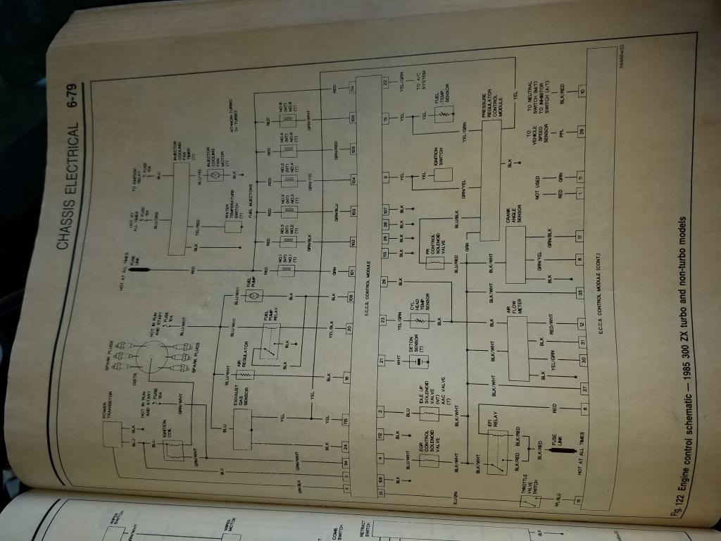
Here is the FSM for my car. Obviously you guys probably have access to this but this'll help me help you guys see what I'm working with. I'm sure I can just get rid of my entire stock ECU but I'm not 100% on what I would do with some things that I believe I'll need. I'll make a list. Pressure Regulator Control Module Cylinder Head Temp Sensor Detonation Sensor Vehicle Speed Sensor EFI Relay? I'm sure I can find everything I need to know about this with some digging but I was hoping you guys might be able to point me in the right direction. And yes, I'm aware that this has nothing to do with the original post but this will lead to either a win or another headache regarding my ignition and timing.

-
The original ECU is still in the car connected to some grounds and power for various sensors. I plan to go through all the wiring for it and try to get rid of it from the car. But everything the MS is controlling is not hooked up to my stock ECU, besides the 12v power and ground to the ignitor (I believe) I don't mean piggyback as in I'm using MS to control one thing and my stock ECU to control another thing. I just meant that my stock ECU is still hooked up in the car, but I don't believe its controlling anything. Like I said, I'll be working on getting rid of it this weekend because that may be an issue. And actually no, it honestly never occurred to me that it could be interpreted that way until now lol
-
Ok, thank you for clearing things up. Now, while using my stock ignitor, the car runs but really poorly. I'm still not able to control the timing besides rotating the distributor. What would the issue be if not my settings in MS? To get spark, pin 36 needs to be wired in to the signal wire on my stock ignitor(since I don't have the BIP373 ignitor)
-
I've got the ignition coil ground hooked up to pin 36. The positive to the coil is hooked up to 12v run and crank. Won't fire. It will only fire when I have pin 36 hooked up to the G/B wire on the power transistor. As for the CAS wiring, I have the G/Y and B/W still hooked into the stock wiring because it's the unused wire and a 12v lead. Scratching my head again.
-
Relaaax. Not all of us can understand everything going on unless it's explained in Laymans terms. I've read the article about the optical trigger wheel and it doesn't say anything about the long tooth for the cam signal. No explanation as to why it's needed I should say. They say to input the teeth as 12-1 But if it's spinning at crank speed, it's going to read it twice? I'm just trying to understand HOW it works, as well as getting it to work.
-
So you're saying I need both the 60* and 360* wires connected to MS? Where would i plug the 360* wire in at the Megasquirt? What would the long slot be used For? Just a position? Or perhaps the greater good lol. Now if I put the wheel speed to crank, I'd have to change the teeth to 24 and 2 missing right?
-
Yeah, I know you've gotta be safe when you first start tuning. I haven't touched the tables much except for getting the car to hold at idle. I want to get my ignition timing all figured out before I start messing with the tables.
-
It's a 1985 VG30ET 300zx. I've put a bigger turbo, intercooler, external wastegate, electric fan, boost gauge, wideband. Probably more but not off the top of my head. I wanted to be able to tune the car to compensate for more boost and better ignition/fuel control. Hopefully run bigger injectors and also E85 in the near future. I wanted to get rid of my MAF and other stock shit like the egr and stuff that requires a new tune.
-
I do now yes, but I thought that the distributor rotates at cam speed? What would changing it to crank do besides it reading twice per rotation instead of once?