

taaron
-
Posts
62 -
Joined
-
Last visited
-
Days Won
2
Content Type
Profiles
Forums
Blogs
Events
Gallery
Downloads
Store
Posts posted by taaron
-
-
So I'm starting to plan on my dash and getting everything in order. I'd like to run a purely tablet driven dash. Most of the sensors I need are accessible via Raspberry Pi running Tuner Studio hooked up to my Megasquirt 2 (v 3.57). Is there anyway to also get readings like, oil pressure, fuel level, gps speed, through to tuner studio?
-
So I've got a 78 280z. I'm looking to replace my center gauges with a tablet, which is going to mean modding my dashboard a bit. I recently for the first time, took a look at the 280zx dash and realized I liked the look of it/the style could make my install easier. Has anyone ever put the zx dash in the z? I know the car is a little wider but I wasn't sure if maybe it'd be a close fit.
-
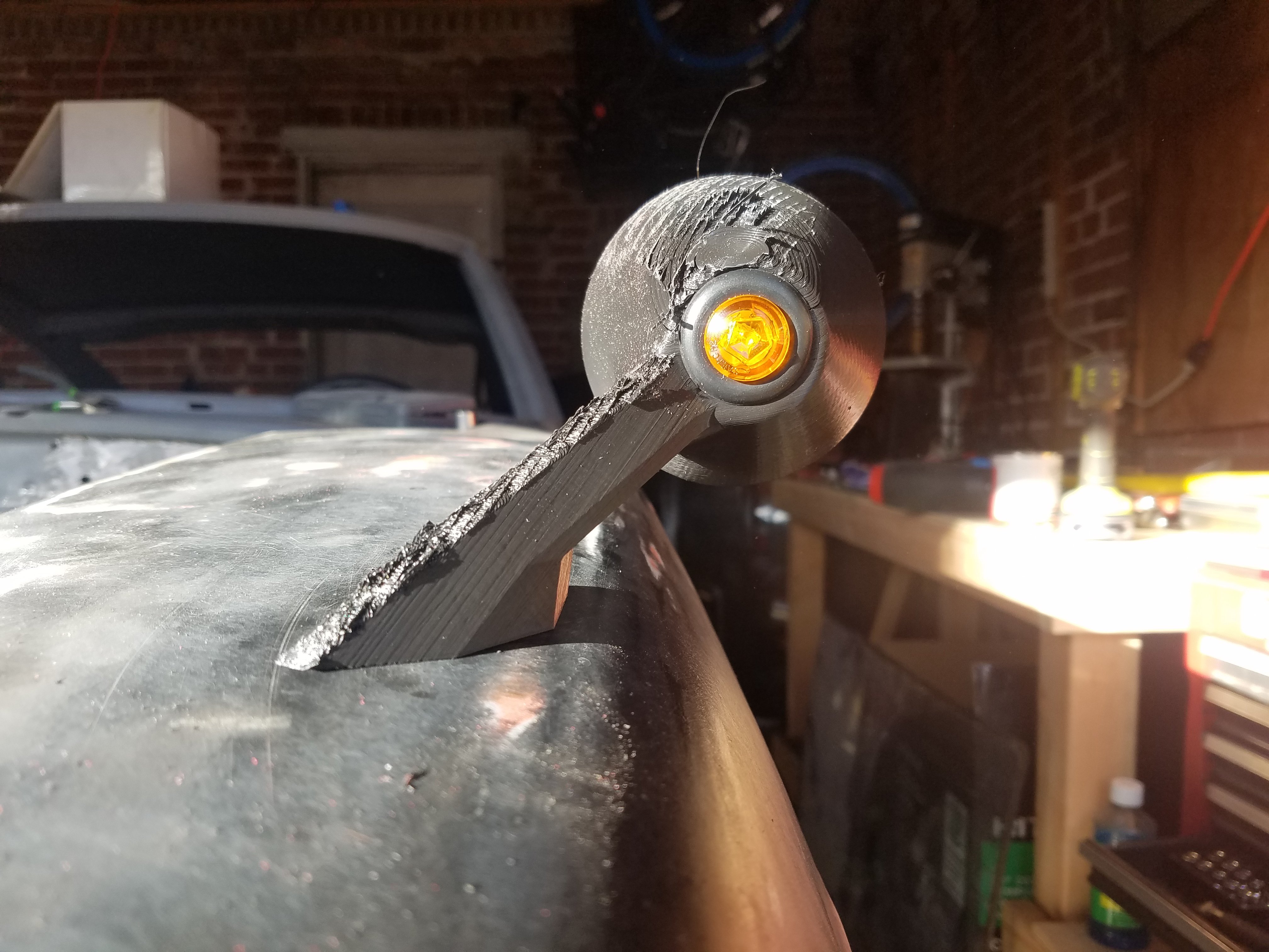
They are turn signals! I haven't had a chance to test their output yet. But I've deleted a lot of lights on my car, and wanted to have some kind of signal output that was different.
-
I've heard good things about PETG. I went to pick some up this weekend and bought the wrong size hahaha. Its nice having the second set available to measure off because its surprisingly flexible. Originally I had a 3mm shell but I honestly think I may drop it down to a 2mm solid. Guess thats the nice thing with having the printer, can experiment as much as I want.
I can take some pictures of the one I have at home, but its not the method I'm going to go. Unfortunately thats the part I want to keep secret until I have everything finished.
-
8 minutes ago, ZHoob2004 said:
Design looks interesting. It shouldn't really matter what material the mirrors are printed out of as long as it's strong enough to withstand the aerodynamic forces and temperature swings the car is likely to encounter. Personally, I would paint the plastic with an automotive paint and primer as part of the post-processing step, which will also help to hide any layer lines that you don't get sanded out.
TBH, this has given me the idea of designing and printing my own mirrors. Perhaps something close to the original long stalk fender mirrors.
Yeah, PLA isn't a good option specifically for the temperature. The outside of the car can fairly easily getting hotter than the glass transition temp of the PLA (un-annealed) and can start to deform fairly quickly. Yeah as far as finishing goes, the thought was give ABS an acetone bath to help seal it up then prime and paint like any other part.
-
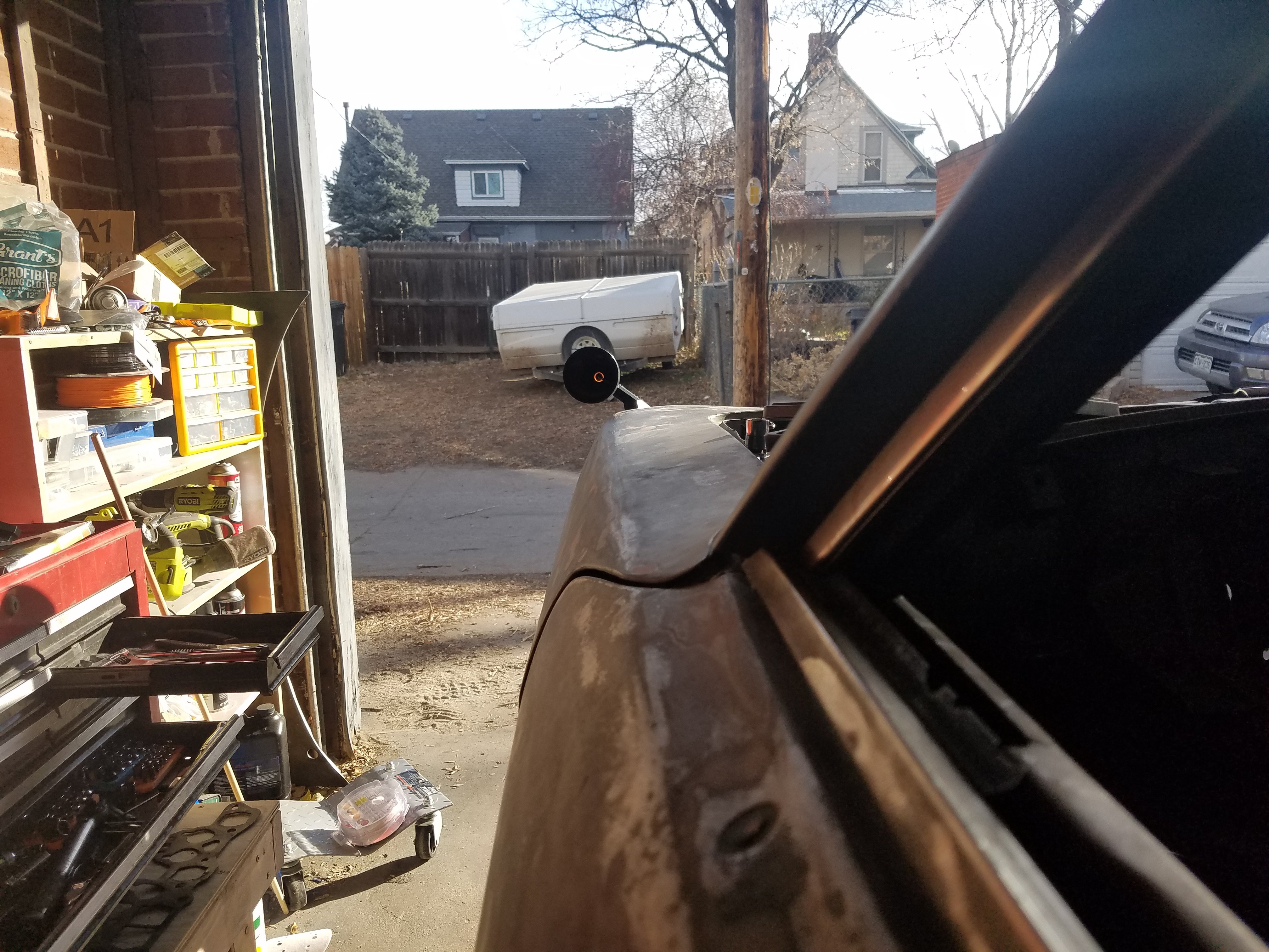
Hey everyone, so I've finally got my car back to where I can start making parts for it. I came up with this design for custom fender mirrors and wanted to see what people thought. Right now they're just printed in PLA (easy and available) but the final product I'd like to get done in ABS or ASA. Has anyone ever printed parts in either of these materials that then lived outside? I've heard ABS isn't great with UV however in researching commercially available fender mirrors, most are also made of ABS.
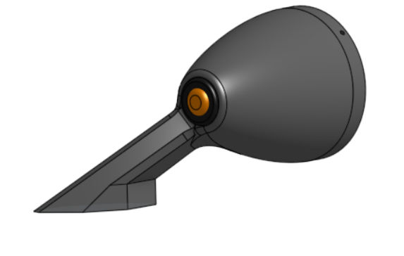
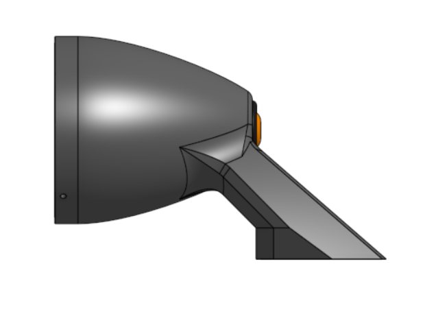
Anyway, onto the design. The idea behind everything was a transition from retro to modern. I wanted to slope the mirror out of the fender, however I did want to keep the classic bullet look, so I tried to make it look fluid. There's a hollow tube for running all the wires through it. The backside features a small turn signal light, the mirror side is going to be something special. I don't want to get too far into it, but the idea is it'll will fix my biggest issue with fender mirrors, their uselessness. If the reception is good, it'd be something I'd consider trying to manufacture (I could do custom designs).
Diameter is 90mm, length is ~150mm, height is ~140mm. Ignore the roughness residual from the printing.

-
Bay looks awesome! I'm in a similar boat where I need some space in my garage back and the engine sitting outside the car is taking up too much space, so I was going to spray just like you did. Glad to hear the mixture worked out, I may follow the same path!
-
44 minutes ago, NewZed said:
Use the "Single Fuel Rail Fuel Injected" diagram here. Ignore the others, some aren't quite right. Leave the unused inlets on the FPR blocked. The supply is at one end of your rail and the FPR at the other. Tank-(prefilter maybe)- pump-filter-rail-FPR-tank.
Thank you so much!! I definitely had this completely bass ackwards. Got this bookmarked now!
-
So I've got a question about the plumbing with this type of rail. I've got one similar that I built, with one inlet and one outlet. I've also got an Aeromotive Fuel Regulator installed inline (2 inlet/outlet, 1 return). I was wondering how I should go about running the lines (I was having trouble for a while getting the car running under any load, and I think I may have been starving fuel). Do I take the line from the fuel pump into inlet/outlet port 1, then inlet/outlet port 2 to the fuel rail which should dead end, and then my return line goes back to my fuel tank?
-
9 hours ago, rossman said:
Sux. I know the feeling all too well. The PO of my car filled holes in the frame rails and corresponding holes in the floorboard with Great Stuff then covered them with dynamat. He told me with a straight face that the frame rails and floor pans were "solid."
Oh man. I thought I was alone with a PO that crazy. My PO "repaired" the floor boards with a harbor freight welder and Great Stuff in all the holes.
-
I've seen it and definitely on my list. I'm semi afraid of having to source all the separate parts hence why I wanted to see if anyone is looking to part with a setup. If not I'll more than likely go your route!
-
Looking to go distributorless. Wanted to see if someone had an EDIS setup that they were looking to part with. Would be going on a 78 L28. Located in Denver but willing to pay for shipping.
-
Sorry should have added. Already running a full megasquirt 2 system (280zx turbo dist and everything).
-
So I've been trying to decide on an engine to put into my 78 project for some time. And this week I've had a few different chances fall through. A little disheartening, but got me thinking about alternatives.
I currently have a 78 with a N42 block and an N47 head. Not looking for a response to this of, buy a P90 head, I know the head I have is the "least desirable" head out there. But I already have it. I believe this means I have the dished pistons, and a compression ratio of about 8.3:1. Say I wanted to take the turbo exhaust manifold off a 280zx, ignoring the different shaped exhaust ports, could I bolt this on? It seems like 8.3 is terribly high and wouldn't be terrible for turboing in theory. Especially if I put on a 2mm metal head gasket to try and lower compression a bit further. Also, if I could do this, would running an intercooler and potentially meth allow me to run this is a little harder a little safer?
-
I can vouch for Chickenman and I know many others can. Hes been super helpful, working with me being a pain in the ass and my less than ideal hardware setup
-
Of course! We wound up going with nylon printed on its side. I'll let you know how it holds up.
-
So to anyone that gets stuck where I did, DONT FORGET THE MICA INSULATOR ON THE BIP373. The car is running now!
-
I've done all those things, according to the msextra manual. I put a 1k resistor in r57 because thats what I had around so that worked.
10v is my main concern because that seems to be whats holding me up. I believe spark is now the only thing holding me up. The battery is good, I had it tested at autozone this weekend, and it lives on a trickle charger.
My MS2 grounds are currently on chassis (I know bad, getting corrected tonight). That chassis ground is also connected to the block in a real shit (greasy dirty) spot, didn't have time to make a longer cable last night to relocate). My battery sits in the back of the car, so it is grounded to the chassis in the back ( I can run it to the block up front if that needs to happen, however I thought the shorter run cable would be better than having an 11ft ground to the block.
I'm going to get all those grounds rearranged this evening and see if that gives me 12v out of that terminal. If not I'm going to start pulling wires one at a time to see where my voltage is bleeding out.
-
Yup did all of those things.
-
So great news update, I think. Followed all the instructions, I now have both trigger signals and rpms showing up. New problem is, I'm for some reason just getting 10ish volts out of my relayboard at the fuel pump/coil+ position. Could this potentially be due to some bad grounding? I initially had everything grounded at the starter motor but learned thats a big No No. I moved it a bit further away but I still need to relocate it to the other side of the block, I just didn't have the terminals on me to make the cable.
-
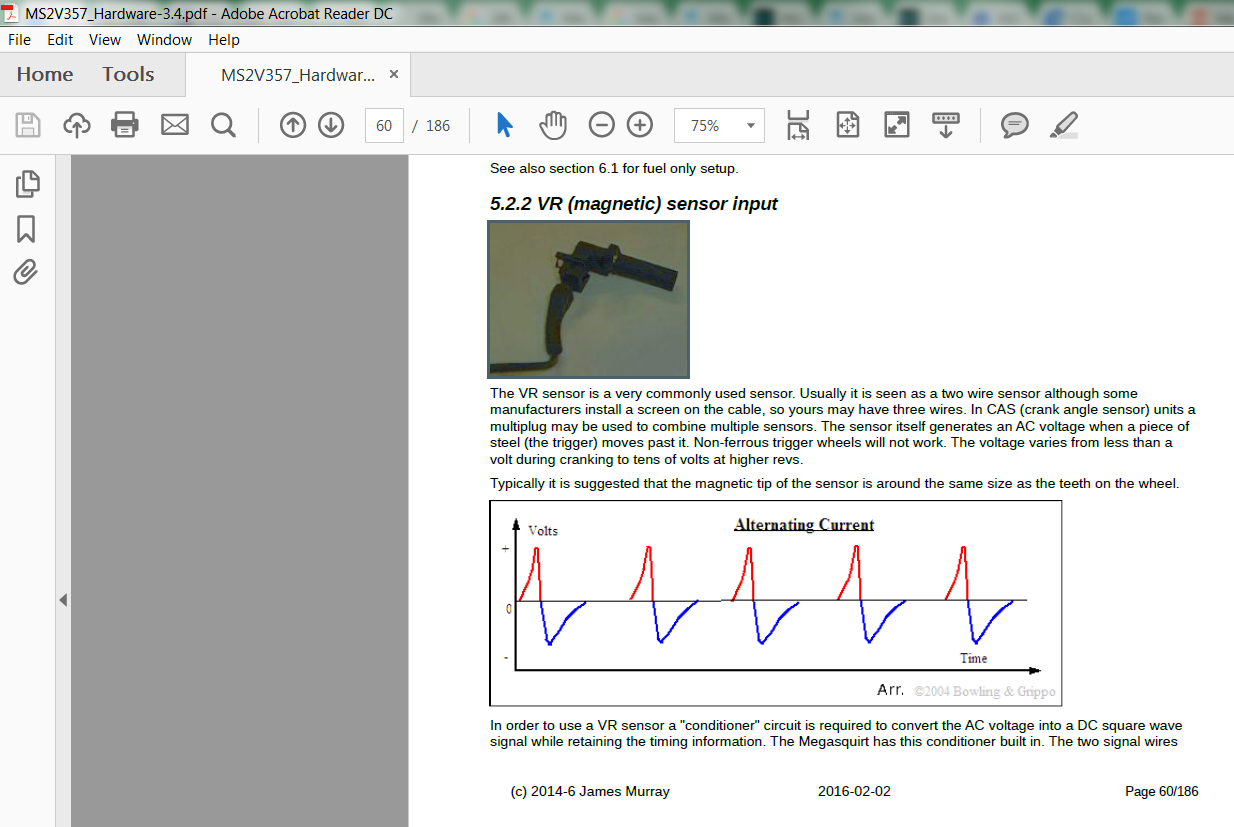
So I've looked at that site, and going through the VR Conditioner on there is different than on the MSExtra manual. Theres a lot more steps listed and at the same time, it calls out these proto areas that don't exist on these boards.
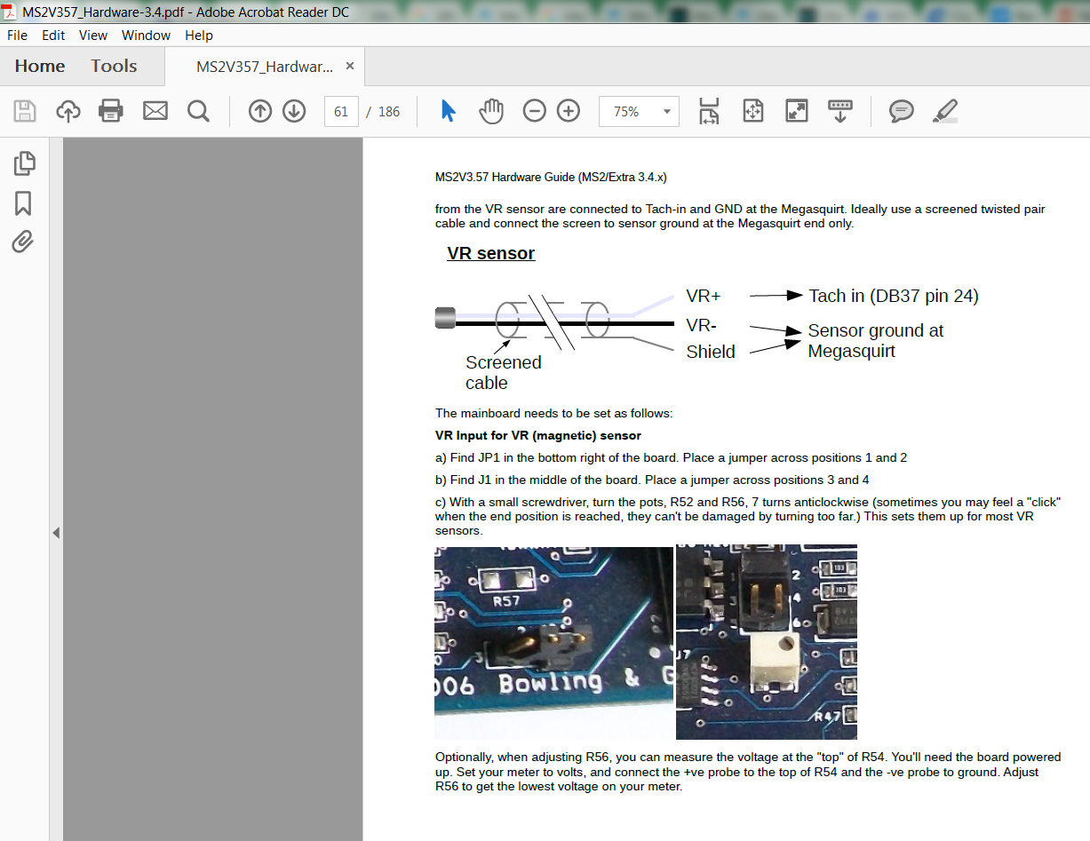
Hardware mods – V3.57
- For a V3.57, you’d have to remove a lot of parts to use the Hall / optical input, so we’ll just bring this in through the VR conditioner instead.
- Place the JP1 jumper in the 1-2 position.
- Place the J1 jumper in the 5-6 position.
- Put a 1K resistor in the R57 slot (Or you can use a 1K pull up in the wiring, as above.).
- If you want sequential coil on plug (or sequential injection with the 3.2.1 code), you’ll also need a second trigger input. Solder a 1K resistor onto a length of wire, and cover the resistor with heat shrink tubing. Connect this resistor-on-a-wire combination from JS10 to SPR1. You could also use PAD7 if you’d rather bring the input in through the DB15.
- Solder a 470 ohm resistor onto a length of wire and cover with heat shrink tubing. Run this resistor-on-a-wire from the 5 volt terminal in the proto area to SPR1 (or PAD7 if you used this in the preceeding step.).
- Connect a 0.1 uF capacitor from JS10 to SG or the proto area ground.
- Install the spark output of your choice. BIP373 or QuadSpark output mods are two possible choices. OEM Nissan SR20DET ignition modules require 5 volt logic level ignition outputs.
-
Hey All,
I just wanted to make a new topic because I have a bit of a more specific question and wanted to make sure I'm absolutely on the right path before I start modifying my board. So I bought a Megasquirt 2 3.57 Assembled board from DIY Autotune. It did not come with the BIP373 transistor (ordered and will be here today hopefully). I've attached pictures of my board and how it currently sits.
I know the first thing I need to do is wire in the BIP373 transistor and follow the steps associated with that. Thats pretty straight forward. The problem I'm having is with triggering. I currently have a new 82/83 Turbo ZX Distributor with the trigger wheel from DIYAUTO. I also have the original trigger wheel that came with the dizzy, just not installed. I was wondering what is going to be my best bang for the buck way to set up triggering. Softopz mentioned going the route of the VR Conditioner. If thats the case, do I just follow the steps listed in the msextra manual (Attached to this post for ease of reading). What about setting up tunerstudio. Also should I be worried with all the wires currently ran on the back of my board.
I should note I'm currently using a relay board and would like to keep it if possible. I'm not concerned with trying to have the most precision triggering possible, I just want to be able to have a car that I can drive again.
-
On 4/3/2018 at 6:14 PM, Slowpoke said:
Nice TPS mounting plate! I was thinking of printing one. You mind Sharing the STL?
Also, when your ready to tune get a hold of Chinkenman. This gentleman knows his stuff and his support and patience are bar none!
In case you still wanted it,
https://www.thingiverse.com/thing:2854991
We're looking at trying to get a nylon piece made, if that doesn't work I'll probably try PETG.
-
I'll definitely share a link to the file once I'm on my other computer tomorrow. Yes its PLA. No its not annealed. Its just in there to hold the sensor right now, the car isn't ready to run enough to heat up let alone run on the street.
That being said, SUPER productive weekend. Got all the wiring in. Getting a usb to serial cable from a coworker tomorrow and should be plugging in tomorrow afternoon (still have to buy the software)! Any words of advice Chickenman?

.jpg.b7c8cd6b3d8708440ab57c2538f07e94.jpg)
.jpg.cb5aef50d584e896fffc630857e5e44d.jpg)
Megasquirt 2 Sensor Monitoring
in MegaSquirt
Posted
I've got the original oil pressure sending unit. Any chance that would work? I"m also just looking at the wiring diagram and cannot figure out where it'd even go