Datsunpowers
-
Posts
16 -
Joined
-
Last visited
Datsunpowers's Achievements
")


-
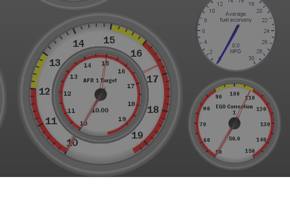
Den here are the answers to your two questions. 1. I didn't think (Leave Valve Closed Above:(rpm) - 7,000) would make any different so I kept the default. 2. I haven't had any hot start issues as my hood has two rows of louvers in it. They came with the car when I bought it. I think this really helps with starting and keeps the under-hood temps down. Looking over the log at Idle I would fatten up your fuel at idle more to bring down the AFR. If you look at your EGO Correction the max it can correct is 8% starting at 40 seconds in. It continues to run at the max correction at 108% during the log you sent. You could add an EGO Correction gauge on your dashboard and monitor how close it is to your target AFR and adjust your Fuel VE table 1 until your AFR Correction is at 100. Currently your AFR target 1 is set to 13.7. Here is what my gauges look like on my main dashboard. Hope this helps, Tom

-
Den, I took a look at the log this morning. I have a couple observations vs. recommendations this time looking at the idle sections only. 1. The TPS varies from 0 to .5 and I think this is causing other issues. Do you think the throttle plate is hitting the throttle screw stop every time or the butterfly is not closing correctly every time? Could it be electrical noise. Does the throttle cable has slack in it? At the start of the log its .02 at the end its .05 one time. Looking at my setup it only varies .01 at idle and has a very stable TPS reading. 2. At 16.833s the timing jumps 6 degrees because of the Idle adaptive advance timing is firing off. Why I am not sure. 3. At 26.433s the Accel enrichment is firing off with a PW spike of 15.5 and then a Timing advancement, but I could NOT see why in the accel enrichment table. Now the timing advancement could be cause by the spike in fuel and then the dip in RPMs. I think this issue need looked into. This should not fire off at idle. 4. At 93.905s the Accel enrichment is firing off with a PW spike of 14.5 and then a Timing advancement, but I could NOT see why in the accel enrichment table. Now the timing advancement could be cause by the spike in fuel and then the dip in RPMs. Again, I think this issue need looked into. The idle controls are different on the Microsquirt vs. the Megasquirt so I don't understand all the settings, but I hope what I found gives you and area to look at.
-
Den the only table you needed to flip the Warm bit at 175 is the WUE table all the other can have a higher temp values. Looking at the log the idle RPMs is on the higher side at startup and is lean. It could make the car stumble if you're driving it when it's cold. Since we are so close with our required fuel, between the two. I tweaked the startup and idle settings. Give this tune a try. 001_Startup _and_Idle_2025-05-30_05.55.19.msq
-
Den the idle looks better in the log you sent me. The AFR readings are steady not like before with the Accel firing off. I would make a couple more small adjustments to your tune. 1. Change your WUE setting from 220 down to 175 or 180. The WARM bit is not getting flipped and several functions use this bit to enable them including warm idle setting to tell that the engine is warmed up. The manual help is not clear what the setting is. When your thermostat opens or a little before seems a good setting to me. I set mine at 175. 2. EGO Correction, Active above Setting is set at 1300: You're not using EGO correction at idle. In the log EGO Cor1 is 100 at idle. It could be a choice you made I wanted to mention it. 3. Review your ASE Taper settings they seem high to me to keep adding extra fuel after startup. Take a look at the settings I sent you. I don't see any other big things out of adjustment from an idle perspective. The big thing you have at ask is how is it running? If its running good drive, it and enjoy. If it's not tweak it and see how that works. Good Luck, Tom
-
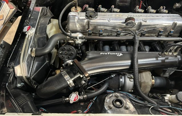
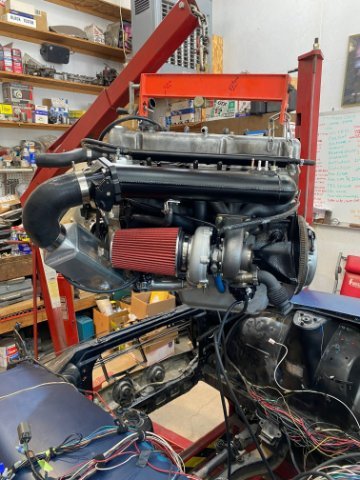
Den, I agree with you that the ProtunerZ guys are very helpful, and stand behand their products. I am so glad that the car doesn't whistle anymore. I am no expert here, so take this as advice. Your mileage my vary. 🙂 The car is a 71 240z. I live at 8,000 feet and I see a lot of altitude change to 5,600 feet in CO, so I am running %Baro. Here is the setup on my engine: 3L Turbo Stroker, 88mm JE forged pistons 8.43:1, Max Speed rods, ARP head, rod, main bolts, Electramotive L7 Cam, Garret GTX Gen II 3071 turbo, Water-to-Air Intercooler, ProtunerZ intake, turbo manifold, downpipe, Arizona Z Car 7 QT oil pan. Megasquirt V 3.57 with the expansion daughter board, sequential injection, 280zx Turbo CAS, GM Truck COP, Bosch 440CC injectors with 43 Psi. This is a new engine that has about 2,000 miles on it. Its running very well over the stock turbo engine I had in the car. I did set up the throttle blade to be completely closed and then configured the IAC to provide additional air to get to the target of 750 rpm. This has allowed me to have it start in the cold at -10F and 90F and warm up properly. I do find it likes a AFR of 13.5 for a good smooth idle at 17 degrees of timing at 750RPM. I enclosed my MSQ tune file Looking over your setup I noticed a couple things you should check. I will make the assumption the engine is stock with no cam and stock cam timing. 1. SYNC LOSS: (This is not good. fix this first otherwise you're chasing your tail) Your RPM signal has noise on it and two dropouts where the rpm goes to zero in a four-minute period. You need to confirm your sending a clean signal to the ECU. This is not my area of expertise with a hall sensor and tooth wheel as I am running optical from the 280zx turbo CAS. Check your sensor gap and grounding and shield grounding. Others here have way more experience in this area. 2. The throttle position sensor: You have 464 steps where mine has 679 steps. I would make sure it has full travel and re-calibrate it. I also noticed that your sensors are unlocked. This could be the sensitive throttle you mentioned. 3. Timing: It can't hurt to double check your base timing. I would confirm it at (Fixed Timing setting set to 15 degrees) with a timing light. Make sure you confirm zero TDC with the piston at TDC. I have had a couple harmonic balancers spin on me. I am not sure how the missing tooth crank wheel bolts to the balancer, so I could be incorrect here. 4. TPS WOT Curve: You have it set to start a zero and it keeps firing off your acceleration enrichment at idle. Your AFR is going rich to 10.4 when that happens. Move the starting point rpm so it just starts to fire when you start to accelerate. Take a look at my tune for a starting point. You don't want to fire off acceleration when its idling. 5. MAP sensor: Looking at the one warm up idle log. The timing moves from 19 to 23 degrees with no TPS input. Then is settles down to 14.8 while the MAP remained fairly steady at 41 kPa. You would think this would change with the timing swings, so check your MAP hose to the MAP sensor and the MAP sensor wiring. I see you have a GM-1Bar sensor configured. On my engine I have a vacuum of 27 kPa. It could be normal for your engine but check for vacuum leaks also. Here is a great article from DIY Auto Tune on closed loop ldle. MS3Pro Closed Loop Idle - Stepper Valve - DIYAutoTune.com 6. I would adjust your timing at the lower values. Set it up so you have 500 = 19 and have 17 degrees at 750. this way it will give you a little timing when the electrical load increases to bring the RPM back up. Looking over the idle/accel tab I have more settings available and a 16x16 table to play with. I think this is the limitation on the Microsquirt vs the Megasquirt. Open loop vs. closed loop: I have had a stock 280 NA with factory injection and MSX fuel only to start with just the air bleed screw and bi metal IAC valve and it worked and idled fine. When I swapped to a stock turbo 280ZX engine with factory injection. I changed the IAC valve to a Ford 2 wire valve and used open loop then closed loop as I learned the system features. Both worked well but I could get more fuel control with closed loop. You have a lot more temperature swings and intake temps with a turbo engine under the hood that effects idle control. Now with the current stroker turbo engine and the PTZ 75mm throttle body. I spent a lot of time getting the GM 4 wire IAC to work correctly with the large throttle body. Any air leak or incorrect IAC travel setting turned into a higher idle. What I do like about closed loop with this current setup is how it can idle when it's cold or hot, electrical loads high or low, you have finer control over the idle. I also feed the gas tank vapor valve (240z 260z has this valve, I think. The 280z has a charcoal canaster) output and feed that in front of the throttle plate to burn the gas vapor off. When it's hot out the gas vapor would change the idle and AFR by two points. Having closed loop and AFR/EGO control corrects for that swing. Burning the gas vapor off from the tank. Do you need closed loop no, open loop can work just fine. If you want better idle control over different variables then closed loop can help with that, but it takes time to set it up from what I have found. The reason I went to Megasquirt or any modern ECU. I was tired of troubleshooting with a voltmeter and a closed system you could barely modify. Now I can tune at my computer and get real time data and logging to review your results. What a step forward, but it's been a long journey learning these features and how to apply them (incorrectly and correctly). I included my current tune and a data log. In the middle and end of the log you can see how it idles. Hope this helps. CurrentTune.msq 2025-05-21_16.32.19.mlg
-
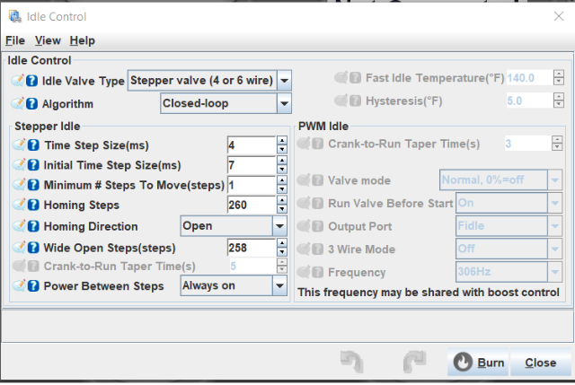
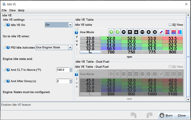
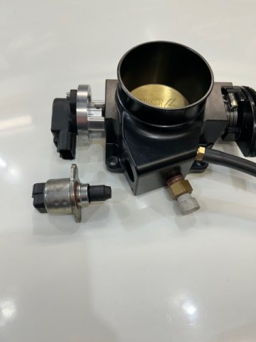
Darom, wanted to say a big thank you. My PTZ throttle body was making the same whistling noise, and it was driving me crazy. Grinding the sharp edges off tonight reduced the noise to an acceptable level. It's much improved now! I hope I can help you out with your closed loop idle settings. I spent a lot of time working to get my car to idle properly at 750 RPMs with the PTZ throttle body. I had to recenter the throttle plate and close the throttle screw closed more with a little grinding on the stop. I also had to change out the GM IAC motor with a different model. The one that came with the throttle body would not close and seal for me all the way. So, I went to the junk yard and pulled several different GM IAC models. The IAC that is working for me I think it came from a Grandprix V6. Here are my Megasquirt closed loop settings. I hope this helps you out. Thanks, Tom
-
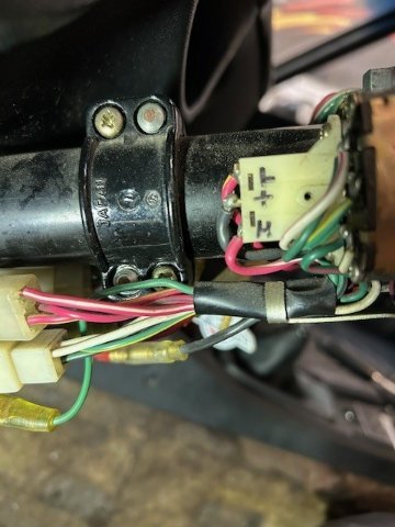
Here is a quick way to check the polarity and the high low switch. Use a voltmeter and ground the negative side of the meter to the car ground. Take the positive lead and touch it to the center of the high low switch. You should have positive +12V with the headlight switch turned on. The low beam wire (Red/Yellow) is at the top and the high beam is (Red/White) at the bottom. The positive +12v will toggle between the two when the turn signal switch is toggled. I enclosed the switch and labeled the different terminals. If that is correct check the polarity at the headlight plug. You should have one ground and +12V at low beam and +12v at high beam. One other thought is check the fuse block and make sure the two headlight fuses are good. You will have one for the left and on for the right light. Hope it helps.
-
MinneZota, I am not sure what you wires you are showing in the picture, so it hard for me to determine what was cut. From the instructions above you do not need to cut any wires or connectors for the swap. You must make the ATO fuse jumper wire and the small jumper wire pictured in the instruction above. By using the two jumper wires you made this allows you to plug them in the existing harness and swap the main red and black wires pictured. This changes the polarity for the LED headlights to work correctly. You can message me I can walk you through it.
-
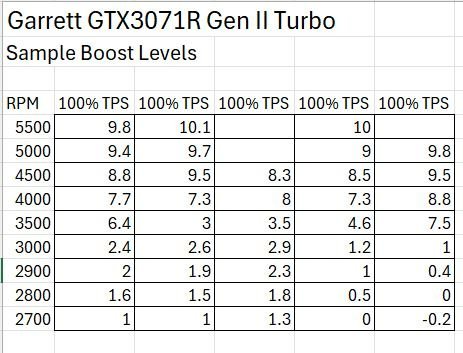
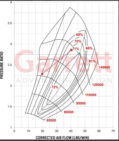
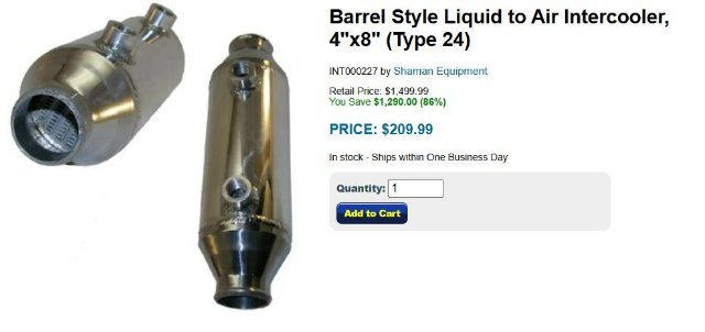
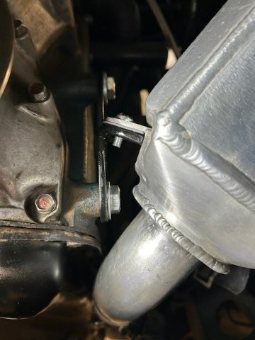
The first engine was a stroker turbo engine where I had hopes of big power with the ProTunerZ manifolds. I wanted a turbo capable of high boost. This was is where the GTX3071R Gen II came in. Well having the wastegate hoses switched and a speed contest with a Toyota Camry TRD and to rich of a tune scuffed two of the six pistons. This toasted engine one, an expensive lessons learned the hard way.😆 It was dam fun to drive at 20 Psi! So Engine number two is a stock setup with 10 Psi and I finished the final intercooler design. Engine three and two years later is another stroker turbo with 88mm JRE forged pistons that I hope to finish the next two weeks. Its finally out of machine shop hell. The plan is to unbolt all the good stuff and move it over to this new engine. I hope the third time is a charm! I tell you all this to say the turbo has been one of the best parts so far it just works and works well at high or low boost levels. Its definitely a quality piece, but wasn't cheap. I did purchase it from Full-Race Motorsport Black Friday sale. I think it was 20% off. I enclosed a chart with several second gear full throttle pulls. Hope that shows you what your looking for. I also enclosed the compressor map from Garrett Boost advisor at 375HP. Garrett Boost Advisor GTX3071R Gen II Turbo 375HP I know when I first started trying to fit an air-to-water intercooler. I could get a smaller barrel intercooler to fit with the stock turbo and manifolds by replacing the J-Pipe and placing the Intercooler in its place. This would leave room for the stock AC compressor if it had AC installed. The reason I didn't go that route as its only rated for a max of 290HP. What you don't get from product description is a lot of tech specs about its cool capacity, so I passed one this one. When I went to the larger turbo and manifolds. I didn't have the room that I did with the stock setup. The compressor housing is bigger on the GTX3071R and this moved everything out against the shock tower. I wasn't a fan of cutting up my new compressor housing to weld a short 90 degree elbow on it. This is where I came up with the current design to pipe it down and up to the larger Intercooler to handle the heat of the higher boost levels. I just didn't have the room with the larger 600HP rated core between the strut tower and the engine. My recommendation is to mock the one your looking at in carboard and see if you have enough room between the engine and the strut tower. Good Luck!
-
1978 Datsun 280z No Acceleration Above 4000 RPMs
Datsunpowers replied to Kad77's topic in S30 Series - 240z, 260z, 280z
I know this could sound a little out there, but this problem happened on our race car where it would not rev above 4500. The valve timing was one tooth advance, because the harmonic balancer had spun and the TDC zero mark was not at TDC after a rebuild. When we took the head off for the second time that's when we found the harmonic balancer mark did not line up with the TDC mark. Make sure your Harmonic balancer reads zero when the piston is at TDC and the top cam sprocket lines up with the cam bearing mark shown in the FSM for the correct valve timing. Hope this helps. -
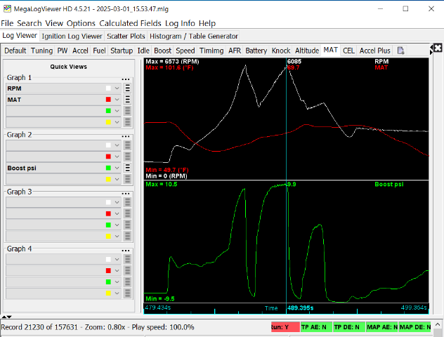
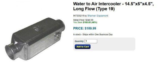
Calz: Thanks for the Recommendation. I do have an Manifold Air Temperature (MAT) Sensor between the Intercooler output and the Throttle Body input that is connected to the Megasquirt ECU. Jeffer949: My current engine is a stock L28ET set at 10 Psi and 440CC injectors operating at 6500 feet. The big upgrade was the Garrett GTX3071R Gen II ball bearing Turbo and ProTunerZ Intake and Exhaust manifold. It was a nice upgrade from the stock setup with very minimal turbo lag. I don’t know the HP level, but it’s been very reliable and fun to drive. I am almost done building my Stroker Turbo engine with 88mm JRE forged pistons and MaxSpeed Rods. I was thinking of turning up the boost a little more, but not to crazy as I daily the car to work if the weather is good. Let me clarify my Intercooler testing. I heat soaked the Intercooler with several boosted passes over 30 seconds to heat it up to 100 degrees with the pump turned off. I then turned on the pump to see how fast it would bring the temperature down to see how efficient it was at removing the heat out of the air stream. This is where the temp went from 100 degrees to 55 degrees in 15 seconds. Now to be fair I did this testing last month when it was 50 degrees out. How well it performs when its hot at the autocross is yet to be determined. I will say before the Intercooler I would see very high temperature spikes under boost and I am not getting that now with the Intercooler filled with Antifreeze. I enclosed a datalog that shows the RPM, PSI Boost, and MAT. You can see how the Intercooler is working under boost. Since I am not seeing big heat spikes under normal driving that’s why I want to turn off the pump until its needed. I have several choices to turn on the pump in Megasquirt. 1. TPS % position 2. RPM 3. MAP (kPi) 4. MAT Temp I am thinking TPS could be a better choice vs. MAT Temp to turn on the pump. Data log: The RPM is 6085, MAT is 69.7 degrees, and Boost is 9.9 Psi in a 3rd gear pull. I agree with you about the Intercooler blocking the AC mount on the left side of the engine. Being the car is a 71 240z it doesn't have AC, but my thought is to use an original 240Z right side AC bracket and convert it to use a Sanden compressor. Here is the link to the Intercooler and Radiator I used for the build.😀 https://www.siliconeintakes.com/front-mount-intercooler/long-flow-style-water-to-air-intercooler-p-219.html https://www.siliconeintakes.com/electric-radiator-cooling-fans/air-to-water-radiator-p-1063.html
-
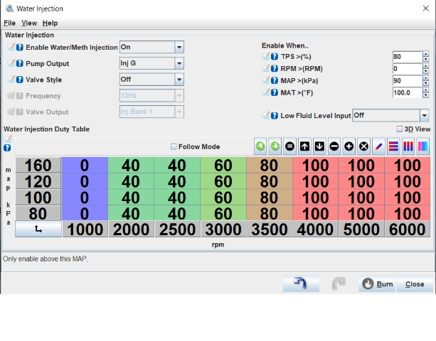
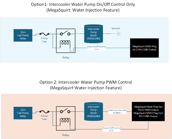
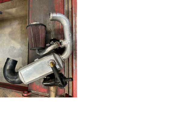
Hello HybridZ folks, I need some recommendations on my 1971 240Z Turbo on how to drive my Bosch Intercooler water pump with my MegaSquirt V3.57 ECU. This is the first time I have setup an Air-To-Water intercooler. What I really like about this setup is the cooling ability of the Intercooler and the very short intake track from the turbo to the manifold. My question for the forum is how to drive the pump as I don’t know how the OEMs do it. The Bosch pump (0392022002, flows 317 GPH, and pulls 3.2 amps) is used on Ford supercharged Mustang Cobras. I could use an On/Off setting or PWM configuration. It doesn’t make sense to leave the intercooler pump on all the time. Currently I just have a switch on the console to turn the pump on and off. Possible MegaSquirt configuration options to drive the Intercooler pump is (On/Off or PWM). Configure the Water Injection option (Pump Output) to turn the pump On/Off at an air temp of 90 degrees. The MegaSquirt will provide a ground to the Intercooler Pump relay. 1. On/Off Control: Configure the Water Injection option (Pump Output using Inj G) to turn an external relay on to turn the Intercooler Pump on with the MegaSquirt below. 2. PWM Control: Configure the Water Injection option for PWM (PumpOutput using Inj G and Valve Output Inj Bank 1). Pump Output controls the external relay on and Valve Output supplies PWM ground for the Intercooler Pump. Setting the Valve Speed to fast will pump to operate properly I hope. I found this setup on the MSEXTRA site from "Prof315" controlling a Water injection pump not an Intercooler pump. System Diagram Here are some pictures of my design that changed over several months. From a performance standpoint I let it heat soak until the intake air was 100 degrees and turned on the pump and it cooled the intake air to 55 degrees in 10 seconds. It seems to work very well and has a quite operation.
-
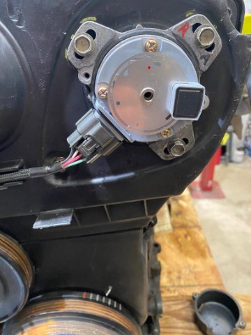
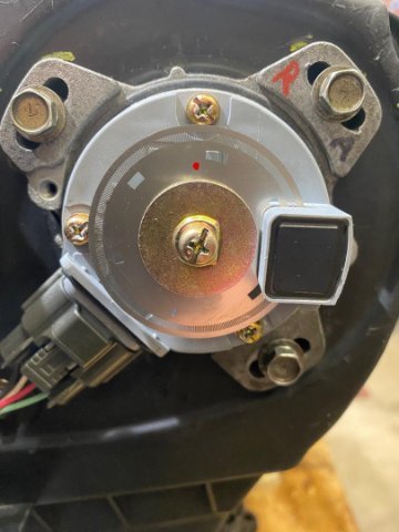
I just recently purchased someone else's RB 240z conversion (Danger Will Robison!). Before I installed the engine in the car, I wanted to start the engine as it's been sitting for seven years. This engine would not start up and just kept backfiring. After verifying the Cam timing for the seventh time and checking CAS output signals. I could not find an FSM reference which way to orientate the CAS disk, so for fun. I just flipped the CAS disk over to give it a try. The engine fired up and ran like a champ. Problem solved! Here are a couple pictures showing the correct orientation for a RB25det NEO Series 2 engine set at 15 Degrees BTDC. I hope this saves someone else hours of troubleshooting!
-
Zev, a couple ideas come to mind. You said you tried larger pump jets, but it sounds like you are not getting enough accelerator pump fuel delivered to the intake stream when it transitions off of the idle circuit. With 45MM carbs with large ventures. When you open the throttle the air velocity slows way down, and the fuel will drop out of the air steam. You need a good shot of fuel to overcome this. Double check that the accelerator jets are squirting forward and at the same velocity. I had the same stumbling issue and two of the accelerator jets were clogged with debris on my carbs. The only way I found this was taking the carb of and watching the fuel come out of the accelerator pump jets. It drove me crazy until I found this issue. If you have a wideband controller installer you could see this lean condition when you open the throttle and transition off the idle circuit to the main fuel circuit. If you PM me. I can share my jetting chart that has worked for my 45mm Solexes. At least you have some more data as jets are expense. Hope this helps.
-
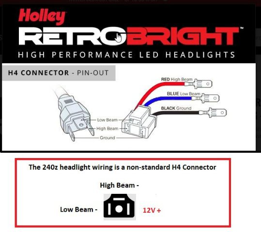
Mike the headlights didn’t have any polarity instructions with them. They did work out of the box in my 69 Camero. When I plugged them in my 240z they didn’t work. This is when I discovered the wiring polarity on the 240z is a non-standard H4 plug. With incandescent bulbs polarity doesn’t matter, but with LED lights it does. Here is a standard H4 plug and the non-standard H4 plug on the 240z. Switching two wires at the headlights switch corrects the polarity for a standard H4 plug. I am sure this applies to other H4 LED bulbs, but I don’t have experience with them.