

OhBilly
-
Posts
114 -
Joined
-
Last visited
Content Type
Profiles
Forums
Blogs
Events
Gallery
Downloads
Store
Posts posted by OhBilly
-
-
If you could post your MSQ, I can go through it for other settings that could cause this.
MSQ is attached. Thanks for the help Matt.
Bill
-
On MS1, it is possible to accidentally set injector bank 2 off, particularly if you try composing a tune from scratch instead of starting with the default tune file.
This article may help - remember, the Stim LEDs are just test lights hooked to 5 volts (and 12 volts will work fine too).
http://www.diyautotune.com/tech_articles/megasquirt_injector_driver_troubleshooting.htm
Matt, thanks for the reply. How can injector bank 2 be shut off? Under "Advanced" and then "Fuel Table Selection" I see you can select Table 2 for INJ2, but I have mine set to Table 1. Is there another way it can be shut off?
Thanks again.
-
Did you ever make any progress on getting bank 2 to fire?
I am in the same situation... bank 2 not firing. Like you, I don't have a noid light nor a stim. I do work with some smart electrical engineers though, and we have scopes, power supplies and multimeters that I have access to in the lab. Matt Cramer, without a stim, how would we go about testing the injector driver circuits?
As a side note, why does it always seem that bank 2 has trouble?
Thanks,
Bill
-
Hi,
Looking for a Megasquirt Stimulator. Just trying to save a bit of money by not buying new.
Thanks,
Bill
-
I'm looking for someone who can physically troubleshoot and repair this board. Any takers? I can ship the board out to you and of course, pay you for your time and materials. I just don't have the time and skills to do it myself. I'm working in the Aurora, IL area and living near Joliet, IL if anybody is close enough to avoid having to ship.
Thanks,
Bill
-
Try using the bootloader jumper when you get that message - 9 times out of 10, that gets the code loaded.
Matt,
I am jumpering the bootloader contacts for my attempts, but maybe the way I've done it is part of the problem: To avoid having to remove the case cover, I soldered wires to the bootloader contacts (1 wire each) and routed them outside the case. To jumper the contacts, I simply twist the ends of these wires together. I don't see any reason why this wouldn't work, unless the wire lengths are too long and there's too much resistance in them.
-
Thanks moby, that helps... and it makes sense. The poster must have got his pin numbers mixed up.
The MS box is getting power for sure because if I power it up without the boot loader pins shorted, the ECU comes to life: the fuel pump primes for a few seconds, and the LEDs on the MS box light up (IIRC, one light blinks for a moment and then the middle LED lights up solid and stays that way). If I keep power going to the MS box this way, after about 10 seconds or so, the relays start chattering like crazy.
Should any LEDs light up when the bootloader pins are shorted? If so, I don't get any.
Is there anything else that I should be checking?
If I can't get it to work, I'll likely send it off to DIY for troubleshooting.
-
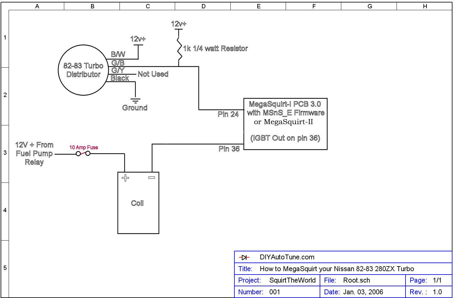
I just finished building a new MS1, V3.0 and have got it installed in the car per the instructions in the install article on DIYAutoTune (I'm using the relay board):

I am attempting to download the MSnS-Extra firmware to the ECU but I'm not getting very far. After shorting the bootloader pins and turning on the ignition to supply +12V power, I'm getting an error basically saying Expecting "boot>", Received " " once the download attempts to start.
I've done a bit of research trying to figure out the reason, and one thing I came across is someone mentioning that this issue is seen when you are not supplying +12V to pin 24, or in my case since I am using the relay board, connection #15 in the above schematic (TACH line) on the relay board.
With the ignition on and bootloader pins shorted, I checked the voltage at this connection and sure enough, it reads in the millivolt range, not even close to +12V. I couldn't realize how this could be until I remembered that there's a 1K ohm resistor between my switched +12V source and the TACH line, per the DIYAutoTune instructions. If I check the voltage prior to the resistor, I do indeed read about +12V (I don't remember exactly, but I think it read about 11.5V).
Now, the question is, should I be shorting that 1K ohm resistor in order to get the firmware to download? If this would work, would doing so cause any damage to the distributor ('83 turbo dizzy) if it gets a full +12V rather than the millivolts it would be getting with the 1K ohm resistor inline? Of course it's easy enough to disconnect the connection to the distributor if needed, but I'd rather not do it unless I need to.
Thanks for any advice,
Bill
-
There's a sticky in the FAQ section that says to use the same settings as those for the DSM 450cc injectors:
Injector Opening Times Spreadsheet
Hope this helps.
Bill
-
Can you purchase an all options included prebuilt board and use what you have and add fans etc as you go or does everything have to recieve a signal in order for the whole thing to work?
DIYAutoTune.com sells prebuilt and complete boards.
And no, you don't have to have everything working and receiving a signal for the complete unit to function.
-
The writeup on our site works for the standard value (390 ohms) of R12.
Thanks Matt, that helps a lot. I've been reading a bit more and things are slowly becoming clearer, but it's definitely not easy... at least not for me. It seems there are multiple ways to make things work and that's part of where my confusion comes from.
-
I figured the 12V pullup resistor for the input back to MS would tell you what it is.
Nope, I'm not quite that bright.
But now I have another dumb question: Is R12 actually the pullup resistor, or something else? I just did another quick search and somebody mentioned that R12 IS the pullup resistor. Right now I have a 390 ohm resistor in R12, but MSnS says that for a 12V CAS the value of R12 should be 1K. Does R12 need to be 1K, plus "another" 1K pullup?
Thanks again.
-
Something tells me 12V...
Well, you're probably right, but I don't think these schematics have anything to do with the CAS output voltage, do they?
The schematics tell you what wires need 12V power going to them for sure. But in reading about the Hall PCB wiring, it discusses Hall sensors and that some of them are 5V and some are 12V. It says that 5V CAS are more common and says if you are in any doubt, start with the 5V assumption and go from there. It also gives you directions for determining if your CAS is 5V or 12V, but it involves actually having the dizzy hooked up with power going to it. My dizzy is buried in the garage somewhere, probably hiding underneath some oil stained t-shirt.
Like I said, you're probably right (and thanks for the help) but I don't see how these schematics tell me what I need to know. Maybe I need to go back to MS school?
Bill
-
I've been searching and haven't come up with an answer yet which leads me to believe that I'm either an idiot, or everybody else intuitively knows this. Or maybe both. Anyway...
My PCB is nearly built, just have to finish it off with wiring up the Hall trigger. According to V3.0 assembly instructions on the msextra site, I need to determine if the internal CAS is 5V or 12V. This will determine what jumpers I need to install as well as determine the value of R12.
I've followed the instructions on DIYautotune for their 280ZX turbo article which has helped a lot, but I can't seem to find this crucial bit of info.
Any help would be appreciated. Thanks.
Bill
-
Mind like a steel trap.......... not.
Ill check tonight if I can remember! bah!
Mine works the same way on most days!
-
Bill, I totally forgot to look last night. Ill try to remember to check today.
No problem, just let me know. I have lots of other little issues to solve in the meantime anyway. Thanks again.
-
I may have some, let me check when I get home. I bought it from ATP turbo and had some left over if memory serves.
Now that's what I'm talking about! Cool, let me know if you can find it or not. Thanks.
Bill
-
Have you tried schucks or napa? Do you have a house of hose or similar place in your town?
I hadn't, but just did. Our local hose supplier didn't have anything, and napa's hose is only good to 200 deg F. Good tip though, thanks for pointing out what should have been obvious to me... check local first.
-
I need maybe 4 inches of the stuff to complete my oil drain, but I'm having a hard time throwing down $8 plus $10 shipping for a foot of it. Anybody have any leftovers lying around the garage they'd like to sell?
Thanks,
Bill
-
from a parts resale? or distributer? Just curious cos 50 is what I spent on mine....
A place called connectorsfast.com sells them and it ends up about $50 shipped. I found a new set yesterday on ebay from a vendor called osidetiger. Total shipped cost was $34.60. We'll see how they look...
-
I have one now that I will be testing. I will update the spreadsheet when I have the data. I measured the DC resistance and it is about 3 Ohms.
Did you ever get around to testing this?
-
I have a set, but I can't tell you if its working or not. but I'll sell it to you for 50 shipped.
Thanks for the offer, but I can get a set of new ones shipped for that price. I'll keep looking for a cheaper set...
Bill
-
Looking for a good set of 6 injector clips/pigtails for the 440cc Supra turbo injectors. Thanks.
Bill
-
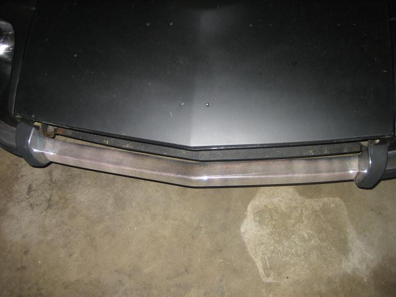
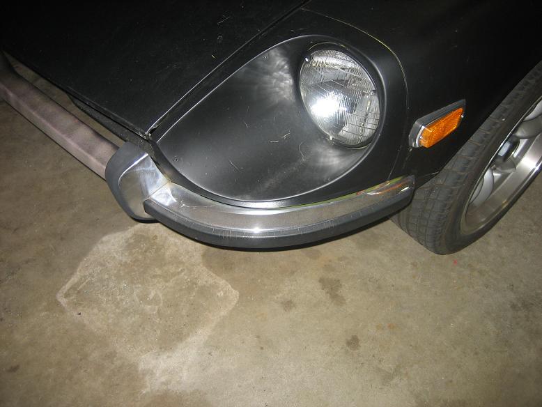
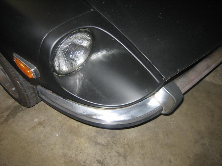
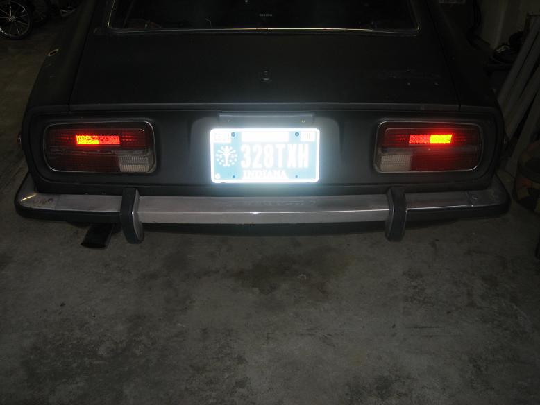
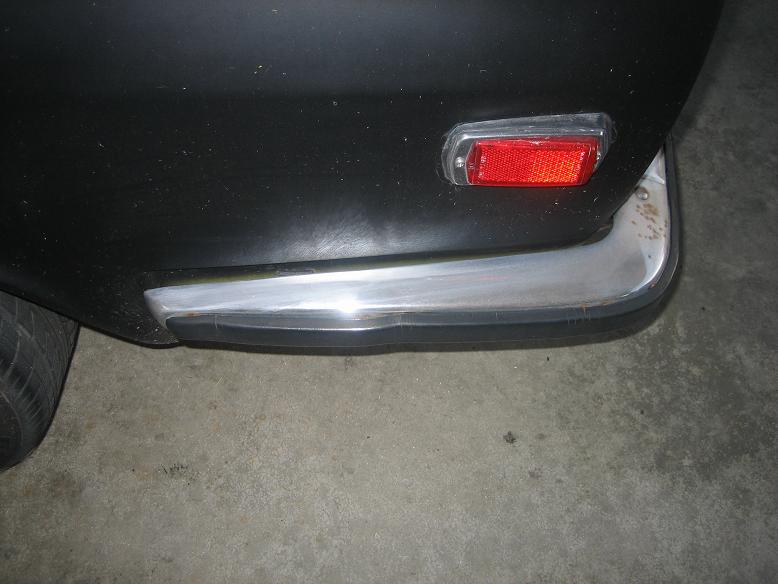
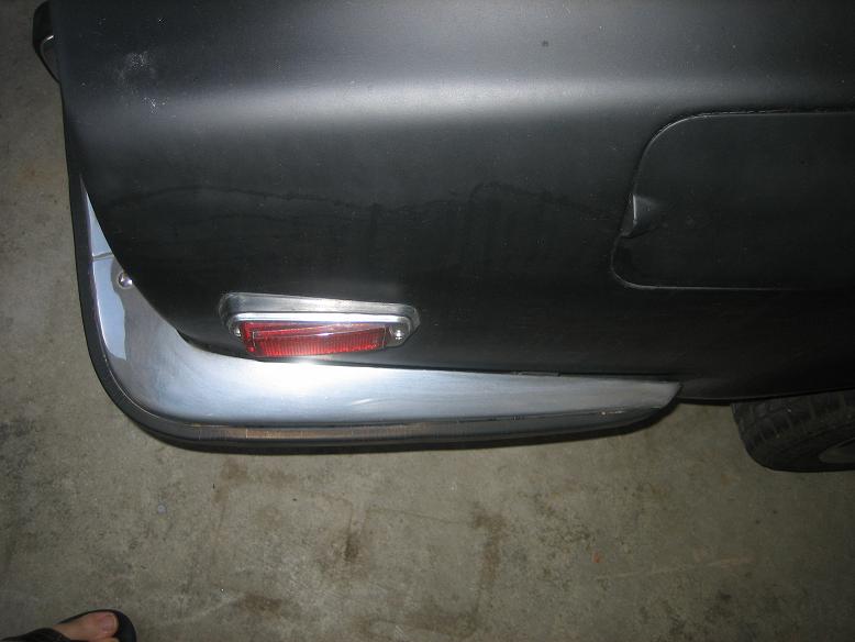
I have a complete set of '72 bumpers, front and rear. They are in pretty good shape and have the original rubber on them.
Outer surface is pretty clean but the chrome is a little faded. There are also a few rust spots on the underside, and the inside surfaces are a little rusty.
Will include all mounting hardware. Bumpers are currently still on the car.
I'm in Lafayette, IN which is about 330 miles south of Green Bay so shipping probably wouldn't be too outrageous. I also travel to the Chicago area quite often, so could get the bumpers that far for you. Chicago to Green Bay is about 200 miles.
I'd like to get $150 for the front and $125 for the rear. Will sell them both as a package for $250. Price does not include shipping.
Bill


injector banks not firing and fidle not engaging relay
in MegaSquirt
Posted
Just an update to let you know I got both banks of injectors to fire.
The problem turned out to be a bad soldering job on my part on a few of the tiny transistors in the injector output circuit. The troublesome ones were Q13 and Q15. I discovered the problem by using a multimeter to Ohm them out. Sure enough, a few of the leads were shorted, and they were shorted on the top side of the board, directly underneath the transistors. The offending bits of solder were so small I had to use a good magnifying glass to see them, and since the were shorted under the transistors, I had to pull them up and off the board to do so.
If you haven't checked out those tiny transistors yet, I'd give that a shot. I thought I was super careful soldering those things on, but they are just so tiny it's easy to bugger them up without knowing.
Thanks for letting me hijack your thread. Good luck to you.
Matt, thanks for the help, I appreciate it.
Bill