
TimZ
-
Posts
2521 -
Joined
-
Last visited
-
Days Won
6
Content Type
Profiles
Forums
Blogs
Events
Gallery
Downloads
Store
Posts posted by TimZ
-
-
On 7/6/2019 at 3:22 AM, 260DET said:
It's for the race 350Z I bought, it has two Tilton MC's and no booster. I've always used a booster because it gives a light sensitive pedal feel which for me avoids brake lock up, anyway It's going to get it's first track test soon so we'll see.
I've have good luck using the electric vacuum pump from a diesel VW/Audi - they are readily available on ebay - search "VW electric vacuum pump". Harder to find is an adjustable Hobbs (or similar) normally closed vaccum switch (i.e., opens when vacuum exceeds a reset threshold)...
-
On 10/23/2018 at 12:42 PM, theczechone said:
@TimZ have you looked at the part's since you installed them?
We used ceramic coating on development engine i worked on, the coatings we used were significantly thicker(0.5-1mm) and chipped off. This engine was subject to high firing pressure loads (yes, higher than yours Tim) and higher temperatures so there was more thermal growth on the substrate(piston) which essentially caused the cracking.
I do think that a chipped coating could get trapped by the ring and score the bore or get trapped by the valve and mess up the seal. But i don't think these failure modes are going to cause a huge detriment to performance.
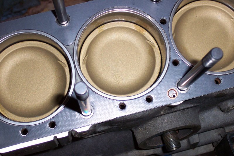
Yes I have ended up pulling the head periodically and have _never_ seen an issue with the coatings. I think 0.5-1mm thick coatings would be a whole different issue (and not a good idea for this application), and none of the mainstream coating suppliers do that to my knowledge.
Not sure on the higher temperatures comment -when I was running the Elgin cam and prior to switching to E85 I was seeing EGTs in excess of 1850 degF - still no issues with the coatings, but I did end up dropping an exhaust valve seat. Even this did not cause flaking on the coatings, but they had to be re-done after the resulting head work. I did follow up with Ferrea "super alloy" valves rated for higher temps and more extensive coatings, as shown in the pics.
-
I've been using ceramic coatings for years now with no such issues. Even if there had been, I'm kinda curious how people think that some "flaked off" bits of ceramic coatings would destroy anything. I used Dart coatings on the combustion chambers, pistons, valves and intake and exhaust ports...

-
On 9/23/2018 at 5:04 PM, Ptero said:
Looks like this is all covered in chapter 2 of the infamous "How to Rebuild your Datsun Engine".
It would appear my comment above is correct.
Yes, you're on the right track. Once you have this orientation between block and head the chain has to have a specific number of links between the marked tooth (marked with a dot) on the crank sprocket and the similarly marked tooth on the cam sprocket. This is what the two bright links on the chain are there for.
Side note: This method only gets you "close enough" to run reasonably well. It doesn't guarantee exact cam timing. To do that, refer to this thread. It's a bit more involved process and requires a dial indicator and a degree wheel, but if you've got the engine out already this a great time to learn the proper way to install and time a cam.
-
14 minutes ago, Villeman said:
soooo.....I am basically an idiot....
the long version, looks like one injector seized or got blocked. I can still hear it firing with a screwdriver, but less defined, and when I pull the plug nothing changes as opposed to all other cylinders. Can I swap over the plug from cylinder 3? They should all fire at the same time, right? Just to rule out the cable..
Yes if it will reach
-
3 hours ago, Villeman said:
Here is the thing. I am positive I could fix the valve seal here and still drive the car (registration going another month before winter break) but definitely not a ring...thats why I dont want to take the head off here, no chance getting it home then (would you say it could be driven 450km in this condition?).
Is there any way to visually inspect the valve seals with the cover off?
If I get it right I wont gain much from a simple compression test because there already is oil in the cylinder? Any ways I will get a compression kit asap and then see
Have you retorqued the head since the rebuild? I always retorque the head on a new head gasket after a few heat cycles. It is certainly possible for the gasket to "settle" a bit and lose some clamping force. I would do this now if you've got access to proper tools - it's certainly not going to hurt anything.
Do the retorque with the engine stone cold (let it sit overnight), use the proper tightening sequence and a proper torque wrench, and back each bolt off 1/8 turn or so before torquing. Just back each bolt off right before its turn to be tightened - don't back them all off at once. Sorry if you already knew all this, but a surprising number of people don't...
-
3 hours ago, damesta said:
That's what I originally thought but then found several websites (not z websites) that said a few mm of play in the wheel is expected, especially with tapered roller bearings on the front wheels of rwd cars. No grinding anywhere. FSM doesn't seem to have an methods of checking bearings with everything still assembled on the car unless I'm just missing them.
I would suggest following the FSM instructions for cleaning, repacking and reseating the front bearings.
God only knows how long it's been since that's been done, if ever. It _was_ supposed to be a regular service item, as I recall.
-
13 hours ago, AlbatrossCafe said:
Good point - updated the O.P.
It is a 1982 stock L28ET with a 1978 280z 5-speed manual trans and rear diff in 3rd gear.According to this page, that puts my diff at 3.545 ratio and 3rd gear at 1.308. I asked him about doing it in 4th gear since that ratio is 1.0 (I thought all dyno runs should be done with a 1.0 ratio gear?) but we started in 3rd gear first for some reason. I think the plan was to move to 4th before my coolant line blew.
Yeah, in general the higher the gear multiplication, the higher the loss from friction. Also 4th is direct drive in this trans, so it's preferred over 5th (no gears meshing at all in 4th). So 18% loss is probably about right for a 3rd gear pull.
-
22 hours ago, stupid_fast said:
@timz, yes the L28ET is only rated for 180hp from the factory, however 148 seems a bit low even for a stocker. I thought I saw some old dyno sheets that were closer to 160whp.
The AFRs at 5000rpm seem a bit rich, but the fuel curve is right on match with the factory fueling map. Possible the AFM spring is worn out.
The OP's rear wheel number is about 18% below the stock flywheel number. The OP didn't specify what trans he had nor what gear he used for the pull, or at least I didn't see where he did. For an "actually stock" manual it''s a _little_ low, like maybe 5hp. For an automatic it's about right.
-
On 9/6/2018 at 3:22 PM, malibud said:
Innovate is terrible i am on my 4th controller (its brand new in the box still in the box they just keep sending me new ones i have practically rewired everything trying to get it to work
FWIW I've been running an LM-1 for years now with zero issues.
Also, if it's truly a stock setup, they only rated it for 180hp at the flywheel to begin with. You're maybe a little low, depending on what trans you have, but that's right in the ballpark of what you should expect.
-
8 hours ago, theczechone said:
if you want more info find Steve Bonk on facebook. I dont think he is on HybridZ but i think he bought the rights to the Potter grinds from Don Potter's wife after he passed. He would have more info on it.
FYI - Steve regularly posts in the "Church of L Series" group
-
6 hours ago, seattlejester said:
The happy byproduct is reducing load, but the main purpose usually is for brightness.
With 40+ year-old wiring you really can't separate the two. LEDs give off more light with less current, less current means less voltage drop to the LED, so brighter still.
Agree with previous posts that adding load resistors is defeating the purpose, and the worst possible way to implement this.
-
I used this company when I had my 300ZXTT CVs re-done, and was happy with them...
-
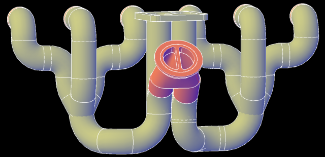
A recurring problem with exhaust manifolds for this head is that as they heat up they grow longitudinally. Since they're held captive on the head, this eventually results in warpage and/or cracked primaries. As HuD 91gt pointed out, this is why the Euro manifolds have them (expected extended high speeds on the Autobahn). For the manifold in this thread, a slip/expansion joint on each of the two runners running longitudinally after the 3-1 collectors and before the wastegate/turbo would help alleviate that. I post about this pretty much every time one of these designs comes up and nobody ever listens 😜
-
*Cough* Expansion joints *Cough*
-
On 6/3/2018 at 2:31 AM, Nicksturboz2 said:
In order for me to check ignition timing on the crank I would have to put a dial indicator in cylinder 1 because there's no key way in the underdrive pulley. it's only been dialed in when the engine was first assembled for the offset to megasquirt.
Wait - what? Am I reading correctly that you have a crank pulley with no keyway? Where are you getting your ignition timing from?
-
same output pressure with less air at the inlet = more work/less efficiency.
I'm only making the argument that the issue isn't different for turbo engines.
-
1 hour ago, SleeperZ said:
Yes, more heat will be generated, but the intercooler will still take most of it out, and the boost pressure is regulated. Net result should be less effect on a turbocharged engine vs. N/A.
Ever noticed the difference on a turbo engine's response on a 70 degree day vs a 90 degree day? It's the same effect. Low density air at the compressor inlet causes heat and lag. This is the same argument that people use to justify spending money an a "cold air" intake that draws hot air from under the hood - it's a poor argument there too.
-
On 5/8/2018 at 12:20 PM, SleeperZ said:
I'll out on a limb and say that N/A engines seem more sensitive to pressure drops across the filter since the engine only has 1 atmosphere to operate on.
The turbo has the same issue, though. The lower the inlet pressure is for the turbo, the harder it has to work to supply a given amount of air, and the less efficient it will be, so more heat will be created.
-
LOL! I was wondering what happened to you!
-
10 hours ago, Tony D said:
I don't ask.
I can't afford it.
I do it anyway, I'm old...what are they going to do repossess my ashen remains from the Neptune Society and resell them packaged in old Cremora bottles to recover my debts?Soylent Green is TONY!!!!1!!1!!!!
-
8 hours ago, NewZed said:
All he needs is the right parts, cleaned up and installed correctly. Blue Loctite on cleaned threads is probably fine. Red Loctite on oily threads is probably not as good. It's the fine details that matter, not just slathering on some red Loctite.
Th OP specifically asked about using a BHJ damper with expect use above 7000 rpm and what to use to secure it. I have very specific experience with this and offered my recommendation, based on several conversations with BHJ after having a damper fail at the keyway. He's got a BHJ damper ordered, so he's already in the realm of "over-doing it", and what to do if you're revving past 7000 is not going to be covered in the FSM. Nobody but you said anything about "slathering on" a bunch of red loctite into a bunch of oily threads. I ASSumed that the OP would be smart enough to chase the threads and clean it first, and it was already mentioned that you don't need to use a lot.
I guess I'm mostly offended my the insinuation that I'm an internet bullshitter with no experience. Seriously? Completely uncalled for.
-
9 hours ago, NewZed said:
Might as well go all the way. Don't want the crank nose end busting off and taking out a crowd of people.
I missed this the first time round, but the part you Highlighted here is the preferred solution that BHJ suggested, which I do intend to do next time I have the crank out. I guess they don't have any experience either and probably just rely in internet rumors on how to install their own dampers though. I left that out before just because it is a bit more extreme than most will be willing to do - that and I honestly don't know that it's possible until I get a good look at the location of the oiling passages. In absence of this solution I'll stand by what I said in my original response.
If you don't want to use loctite I don't really care - the original stuff works great if you're never going to rev past 6400.
-
1 hour ago, NewZed said:
It was a good discussion. My preference is to do things to the appropriate level maybe with a little bit of insurance.
Duragg spends a lot of time at 7500 RPM, maybe higher. He got deep in to transmission synchro design to get his trans to shift well up there. Maybe he has some real-world L-series knowledge to pass on. He has since switched engines but he used to have an L. I don't know if the at's really work but it's worth a try. Mine's just a test.
I'm confused - did you think that CM and I weren't talking about real-world experience? WTF
Also I was relaying much of what BHJ TOLD ME TO DO when I had one of their dampers fail. You should know by now that I don't just make this shit up.


How tight should center main bearing be?
in Nissan L6 Forum
Posted
Read through this thread a couple of times for some great pointers on exactly the part of engine assembly you appear to be venturing into. The title is misleading - they start off talking about the Kameari tensioner and then spend the rest of the thread talking about how to properly assemble the engine. Great advice from some really knowledgeable builders.