Search the Community
Showing results for tags 'Cas'.
-
Hi guys, first time posting here, working on my first RB and I need a little help! I'm having a weird problem with the RB25 I built for my 280z. I just recently put in the motor and haven't gotten it to start yet. I am using a Haltech pro plug-in ECU so that is helping immensely with diagnostics but might be part of the problem lol. So basically I have been able to crank over the engine but I am not getting any signal from the crank angle sensor, which in turn (correct me if im wrong here) is giving me no RPM signal, and not allowing the injectors or spark to fire. Essentially the ECU is unaware the engine is turning. I checked the power and earth of the connector, and also checked continuity from the ECU plug to the CAS, and made sure it was the correct pins for the ECU. Its a brand new wiring specialties harness. On the Haltech I made sure the trigger type was set to the correct one and opened a trigger counter channel so I could see if the ECU was getting any pings from the sensor (nothing). Every time I plug in the CAS with power to the ECU I do get a ping so im thinking the ECU should be okay? So, I got a new (used but in beautiful condition from japan) CAS and hooked it up, thinking that would solve the problem but it persisted. I found it unlikely that I would get 2 bad CASs in a row so I tried to bench test my new one. I gave it constant 12v to the power pin and strangely got 12v out of both data pins no matter what position the shaft was in (this might be just how it is but I would think you would only get voltage at the 1 & 120 degree positions?) I am just using a multimeter though so without am oscilloscope its hard to tell what is going on. Not sure what I should be seeing or if I would even be able to see anything at all. I have a series 2 with the black plastic CAS TL;DR Are these CAS sensors known to go out or am I doing something wrong? They are expensive but my next step is to get a brand new one from Raw Brokerage when they get them back in stock because I can't think of anything else that could be going wrong. Thanks in advance
-
I have a 280z with an 83 l28et swap. It has had a 3000rpm cut out for some time. I replaced the cap and rotor last night and after about 1 minute of idling fine it just shut off. Tried restarting and now i do not have injector pulse or spark. I belive the Cas has gone bad. My question is should the green signal wires coming to the Cas have 5v whenever the switch is on and the cas is unplugged? Or should they act as grounds when the optical reader goes over the slots in the encoder wheel
- 4 replies
-
- Electrical
- Missfire
-
(and 3 more)
Tagged with:
-
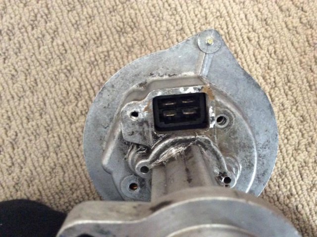
I am building a turbo L28 engine stroked and bored to 3.1 litres with an upgraded turbo. I have the 1983 CAS dizzy driving my Microtech ECU and Igniter box. I don't have the wiring harness for the dizzy that has the Green, black, red, white wires from the dizz going to Gr/Ye, Black, Bl/Wh, Gr/Bl wires in the EFI harness. I have read every post on this and there are some that describe the connections that correspond on the dizz end to the colours BUT there isn't one that correlates with another, in other words there are CONFLICTING posts. So I really need to get the correct way round. Here are the options I have seen. Looking at the dizzy four spade male connector box with the screw hole for fastening the harness on the top left corner.(see pic): One post says starting at top left going clockwise: Red, Green, Black, white. Second post says (same rotation) : Green, Red, Black, White. Also, if I am reading the FSM correctly it agrees with post one above. Can anyone Please help and confirm which is correct? Many thanks guys. Andy
- 4 replies
-
- connections
- harness
-
(and 4 more)
Tagged with:
-
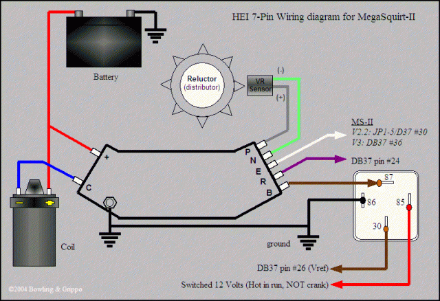
I'm doing some research on using a GM 7-pin HEI module with MS2 and have reached a dead end on one point -- can I (or does it make sense to) use the stock ZXT Optical distributor with the 7-pin HEI? The megamanual (http://www.megamanual.com/ms2/GM_7pinHEI.htm) shows the setup with a VR distributor and explains how the HEI module conditions the VR "AC" output into a "square wave" signal that MS can use as a trigger input on pin #24. Can the ZXT Optical distributor output, which is a "square wave" be used as an "AC" input to the HEI? Seems to me that would not work properly, if at all. Or could the Optical output signal be routed directly to MS pin#24, skipping the VR conditioning of the HEI module? In that case, is there any advantage to the 7-pin HEI over a 4-pin HEI? Whoops - one question turned into several. Any thoughts, conjectures, ACTUAL EXPERIENCE with this setup appreciated.
-
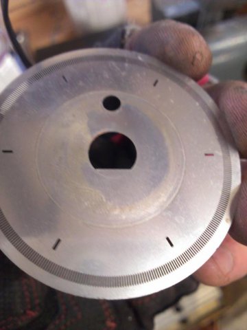
So I noticed an easy way to tell what orientation your chopper wheel is when you do the 300zx ecu swap. Notice the attached picture, how there is a circle punched in by the top piece? It competes the notched out space in the CAS, that indicates the top. The bottom doesn't have anything that could punch out a circle. Just a thought. (Yes, I know the pictured chopper wheel is a 280zx wheel, I just installed mine)


