
MONZTER
-
Posts
818 -
Joined
-
Last visited
-
Days Won
16
Content Type
Profiles
Forums
Blogs
Events
Gallery
Downloads
Store
Posts posted by MONZTER
-
-
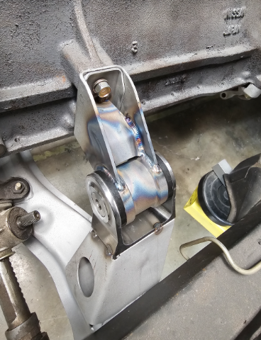
I finished up the front crossmember and motor mounts
Started with a stock crossmember with the need for new engine mounting since I moved the engine in the chassis back about 1 inch.

I extended and boxed in the existing upright
Some grinding and blasting to clean it up
3 D printed mockup of a machined bracket I made to accept the moustache bar busings. I designed these years ago and have been in the NA car for 15 years. Worked well
I machined this weld in bracket out of a solid chunk of steel because I wanted the details for the bolt holes and you could not do that with bent sheet metal. Stupid but fun.
More soon
-
 2
2
-
-
10 hours ago, DuffyMahoney said:
Man, how did I miss this thread! Amazing work. Thanks for posting.
I love your design work.
Thanks, I enjoy keeping up with your projects as well, nice work you are doing on the intakes. I machined this plenum years ago. Made from 2 halves and welded together. Hoping to one day run it.
-
1
-
-
23 hours ago, Leon said:
Did you 3d scan the z32 backplate and constituent parts?
No, scanner, I want one but not yet. Just did all the suspension and reverse engineering old school with calipers just measuring. It's all pretty simple stuff
-
1
-
-
7 hours ago, Leon said:
Wow, gorgeous work. Do you have more pics of that rear caliper adapter?
Here are some more pics
Started with a backing plate from a Z32
Here is the CAD model where I got it all worked out for the proper spacing / fit, ect. Machined the parts from this CAD
This is the first fit check. You can see how the rear hub bearing was modified for a 5 bolt Z31 turbo stub axle bearings and CV flange
Just some final pics
-
Hey Derek, you know my neighbor John at HyTech. Fun stuff. Someday a LY head if we could find the time?
-
2
-
-
Ill Put some more pics of the diff mount/cradle and the trans mount.
Yes, doing all my machining on a 3 axis using SolidCam.
I buy the Aloding coating and the acid prep/wash from Aircraft Spruce. Its easy to do everything just has to be spotless clean and degreased.
I designed and made this diff cradle so many years ago I had to dig up pics. Dont think anybody had something available back then This pic dates back to 2001, thats how long this project has been going. All the turned parts are done on a manual lathe and I did not have CNC back then so its all done on a manual mill as will. All 4130 steel, pretty light actually. Just a hobby so no hurry I guess
Front diff mount is two OEM mounts cut in half and weled together, I integrated the solid mount into it as 1 pc.
Here are some CAD pics of the mount. I actually have moved the engine back about 1 inch so I needed to make a new trans mount. Wanted something to go with the new design front motor mounts Ill show soon when I finish up the cross member. The bushings are from the outboard rear control arm urethane kit. I Its steel and aluminum contruction.
I still need to put a finish on it. But I wont probably use it now as I am going to replace this S15 Trans with a Nismo 6 speed. So Ill have to modify the design and make some new parts.
Front crossmember and Front suspension coming soon
-
1
-
-
Duals, oops just a typo, duel exhaust pipes like original, thanks
-
Back to work on the Z Turbo car and taking a break on the NA car after finishing up the body work. Time to dry fit the rear suspension for the Turbo Car.
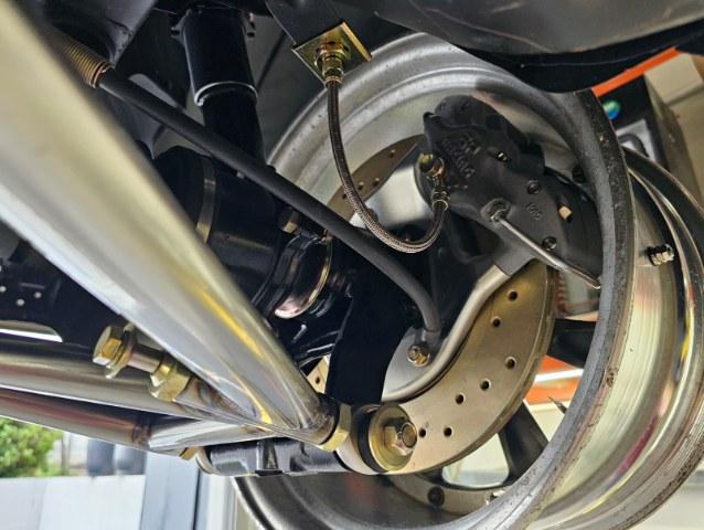
Designed and built my own control arms and rear support years and years ago, finally fitting it up. They are 4130 seamless Chromoly that I polished welded then clear powder coated.
Here are the rear control arms. I stuck with the standard urethane mounting bushing fror the inner front pivot location, but used really nice Teflon lined Aurora rod ends everywhere else.
I had some 6-4 titanium bar drops and plate, so I was feeling creative and made all the big control arm bolts from the titanium
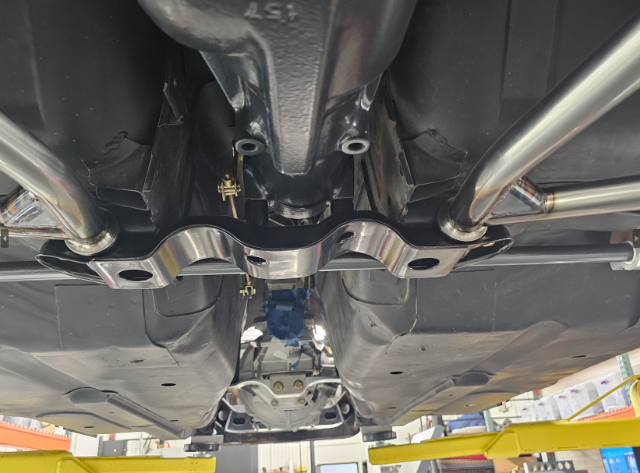
Here it is all installed with the brakes and custom parking brake cable as well as custom CV axles, Diff mount and front mount
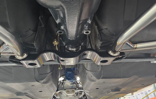
This is a custom front diff mount with a double hump for the duel exhaust that will fit in very nicely. The Diff is an R-200 with 3.70 gears and a Quaife Limited slip. Can remember where the diff cover was from, but I think it was a Nismo part.
I bent up my own sway bars from StressProof steel and made two point adjustment links for the end.
I machined some mounts with solid Teflon busings for the sway bars, similar tot he 280z placement, front mount style
The bar is sitting too low and will hit the duel exhaust pipes so I need to remake the mounts and raise the bar higher in the chassis.
Thats it for now, on to the front suspension and crossmenber next.
Let me know if any questions, clarifications or more pics.
Busy Summer.
-
3
-
-
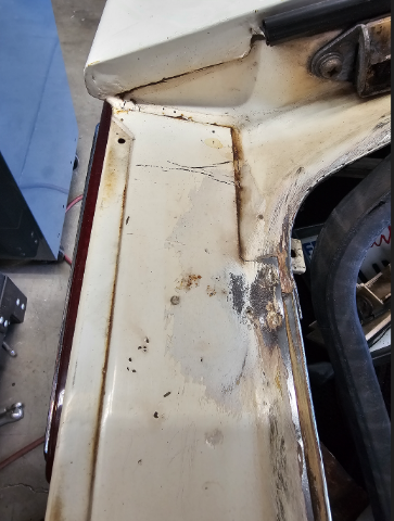
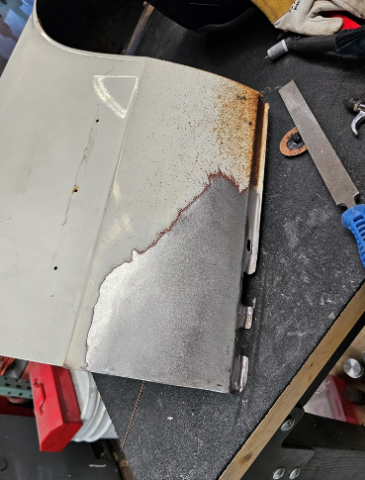
Last bit of body work was the hatch slam. I did not replace it entirely. After getting a Tabco replacement and then a classic fab replacement, I decided mine was not bad enough to justify changing the entire part out and reducing the originality as the replacement parts are not a 100%
The original paint
Drilling out the tack welds
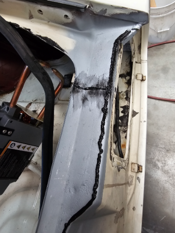
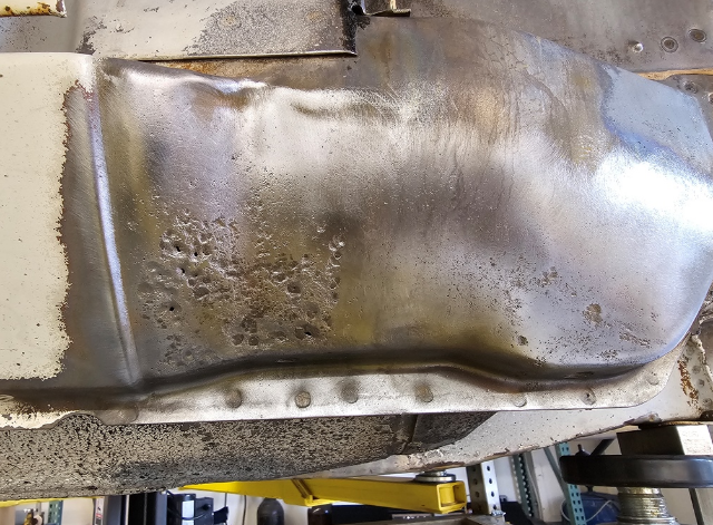
After drilling out the spot welds and cutting part of it away, I blasted the undelay of framing. There was some corrosion deepen than I liked so I cut it out and patched it. Then ground it back and sprayed it with a weld through primer
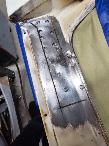
Next I removed the rest of the panel, blasted it and replaced the little bit of rusted metal. Tig welded it and ground it flat along with some dolly work to make it flat after welding
I then tig welded the old spot weld location and ground them flat so it looked like a new panel again.
All the underserface of the rebuilt hatch slam got coated in weldthrough primer. I then applied a weld through seam sealer.
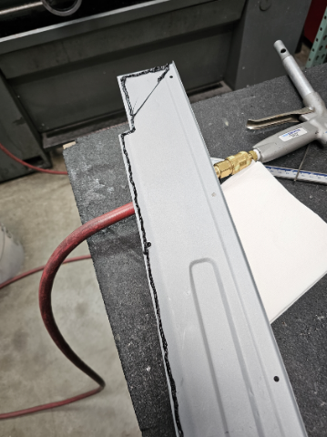
I used the old pc of metal to mark the exact location of the original tack welds
Final to tack weld it in. Looks great and factory original in my opinion
-
2
-
-
Welcome back, I think you unfortunately find things have gotten quiet around here. Face book groups, scammers and short attention spans are the new norm. I came back here after a 10 year absence as I missed the old times too. Still lots of great info to be found, just not the level of new content we remember.
-
1
-
-
Then on to the front fender, Inner and lower.
Another KF Fab part fitted in and TIG welded
Cleaned up the weld beads and spot welded it back to the lower fender return
Same deal on the lower fender. lots of small tack welds to keep it fron warping and small welds. I kept the original lower flange of the fender so the fit would not change. It cleaned up nicely with some blasting, and will keep the original fit and look of the fender
For TIG the metal needs to be perfectly clean forpretty welds, but the overlap of the inner fender made this difficult, but they will look fine when ground back.
A grinder, a file and a shrinking disk got it straight. A skim coat of filler will probably be needed to make it perfect as I cant get behing the repair to dolly it out perfect.
The Hatch slam is up next
-
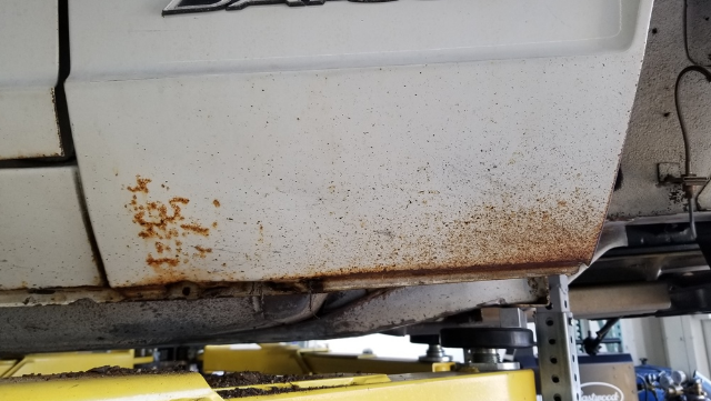
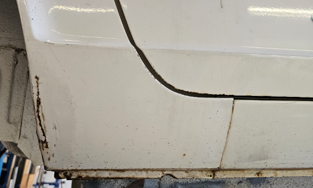
Here are pics of the front rocker panel and front fender work. All the same concept of only removing what was necessay and trying to keep it as original as possible with little to no filler.
All original paint and never worked. Looks pretty good
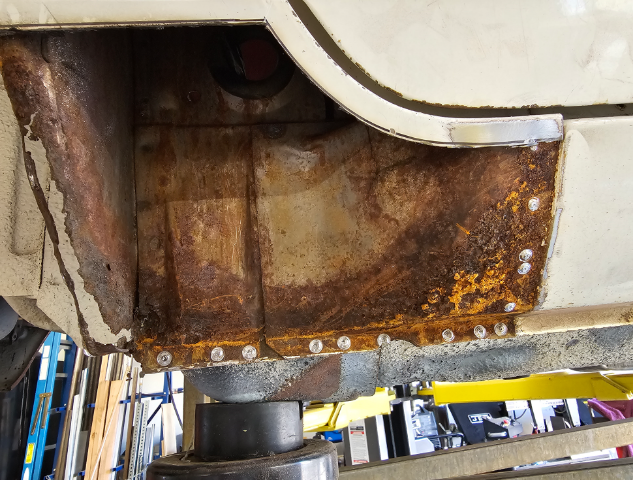
Whats hidden
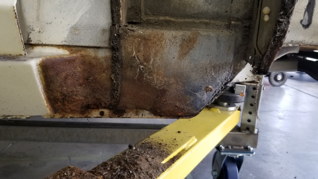
After blating with crushed glass
Cut out the old, you can see the inside of the rocker was perfect and clean. the rust comes from the overlap of the inner fender and the front rocker. The cowl drain dumps back here and it just fills with wet dirt
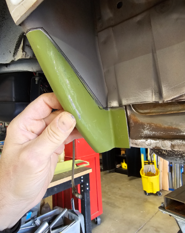
I bought a KF Fab full rocker and only used the small pc to repalce the area. The fit is really good on these parts
TIG welded it back in. Carefully only 1/4" at a time jumping around with an air quench. Some quick grinding of the weld bead and it blends in perfect so it doesnt even look repaired.
-
4 hours ago, madkaw said:
Are you fill welding with silicon bronze ?
No, Just ER70S-2, works well with the tig and low amperage, so no distortion from overheating or cracking metal like it MIG. On headers I would use silicone bronze to weld the primaries to the flanges.The heat cycling needs the ductility of the silicon bronze, but on a body panel I dont thinkit is necessary unless you were trying to flame weld and minimize warping.
-
19 hours ago, Leon said:
Threads like these are what makes HybridZ special. Bravo! How did you develop your welding and metalworking skills?
I miss the old days of the forums. I would not call it a skill, but just some practice over the years and figuring out what works, and what not to do, usually the hard way. So dont be afraid to try and practice if you enjoy this sort of thing. Its not great work, but good enough to satify myself. I have a friend who welds, he has talant
-
1
-
-
I dont want any filler, so I fit each part perfectly with a butt joint, dolly it out where possible, then grind it flat and smooth for an original fit. before any welding I prime all parts on the back side and pinch points with weld-thru primer
the arc and inner rocker are new in this picture
then the rear of the rocker, putting back the spot welds in the OEM position
Some more primer to look super clean and blend in tot he original rocker which was perfect everywhere else
Finally fit the outer skin and tig it in small steps so no warping
Some more smoothing of the welds and original spotweld locations used
Just a small skim coat of filler on the upper weld seem, but making sure to leave all the factory spot welds to show through the paint.
Other side is the same, so on to the front fender next
-
1
-
-
Been busy working on the body of the NA car. Overall in really good original paint condition. But of course the common areas still need to be replaces even in a low mile California car. So I got busy cutting and welding.
The KF parts are really nice but I only want to replace as much metal as trulely needed, so instead of just replacing the entire part, I grafted in what I need to keep it as original as possible. Here are some pics of the first dogleg
What is hiding inside you ask
Surprise
cut it all out
start fitting rebuilding from the inside out as how it was originally done
Blast it all clean and start TIG welding
-
Even if 100 people commited to purchase, its still tiny small numbers vs an OEM production. Its got to be done out of passion and at least not to lose money.
This is why this is such a huge acomplisment for someone like Derek, We are fortunate the passion runs deep. I cant imagine the hours of "un-billed" time
-
3
-
-
No English version I could find, but they show some pictures of the concepts they are working on
-
Has anybody else seen this video yet? It's JMC announcing more new cylinder heads for the L series. The FIA/Safari head a twin cam head, s20 head and another L series head. what do you guys think?
I wish they did a LY head, with modern chambers and ports
-
1
-
-
You’ll lose nothing in my opinion, Fuel injection has a tunable acceleration feature just like a pump on the Webbers. I ditched mine for fuel injection and it was way better everywhere and no hundreds of dollars to make a jetting change, just a few click on the keyboard to make changes and tune it. I would never go back.
-
2
-
-
In the past when I would bench and smooth out casting lines in parts you would always see the smooth ground areas in contrast to the original casting finish. What I would do is blast it with a heavy 36 grit aluminum oxide to add even texture on the entire part, then Vapor hone it to brighten it up. It looks great, almost as if it were originally cast like that. So something to consider vs just glass bead if you decide to smooth out any of the maching marks and go with a more classic cast look.
-
Looking good to me, lets see some detail shots of the machining that you are not happy with. Are you going to bench it down? Whats your plan for filters?
-
The quality looks great, so good way to do it. The cost of materials in the USA, particularly in California, makes it uncompetitive even compared to other parts of the country. It's likely that the material costs alone here are as high as what you paid for the finished part. Its why I just make parts for myself anymore. I have to justify the time and cost with love of doing it as a hobby
-
I still check in once in a while and still work on my cars all the time, but it bumms me out that its so quiet around here anymore. Im not a social media guy or have time to produce youtube videos for self promothion, so I just quietly enjoy my projects and keep busy. Seems all the forums for cars and motorcycles I use to participate in are pretty quiet. Times change, but not all of us follow along.
Thanks for all the help along the way
-
1
-


A tale of two Z's - NA vs Turbo
in S30 Series - 240z, 260z, 280z
Posted
More pis of it finished up
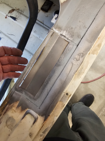
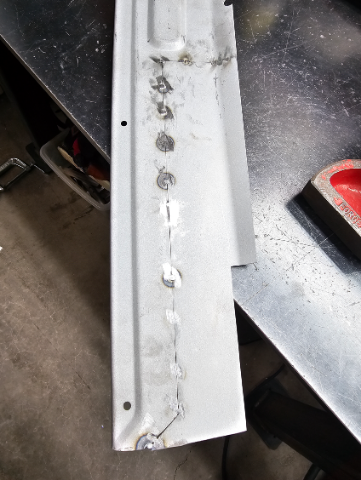
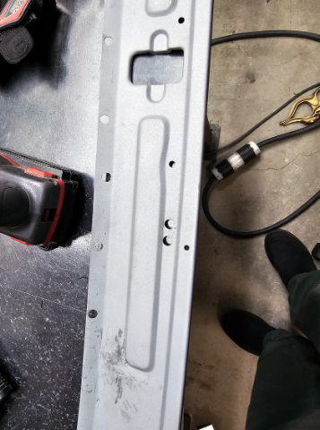
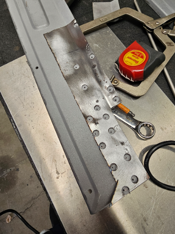
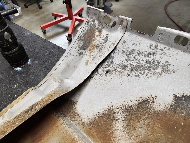
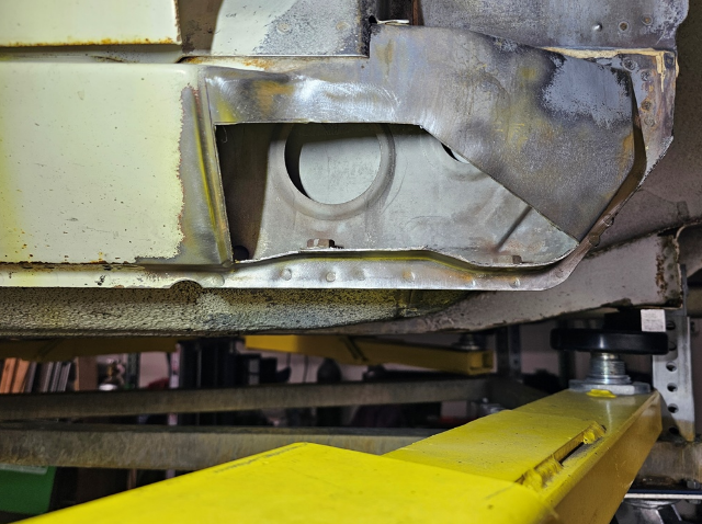
The bottom plate was beat up a bit and bent from floor jacks. So I took off the old one by drilling out the spot welds. I then drew up the shape and had a new one laser cut.
The center plate that is welded to this plate, I re-made it as well, but out of 304 stainless steel. This way I can leave it a brushed stainless finish after powder coating and it is a good place to use a floor jack.
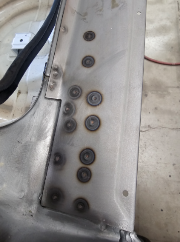
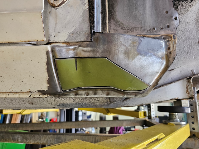
I then spot welded on the larger plate in the original locations
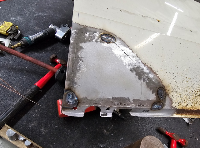
I then tigged the seam between the spot welds
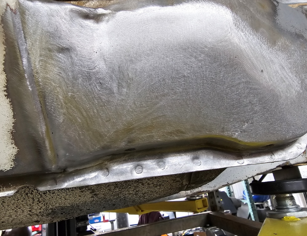
Then tigged on the center stainless plate
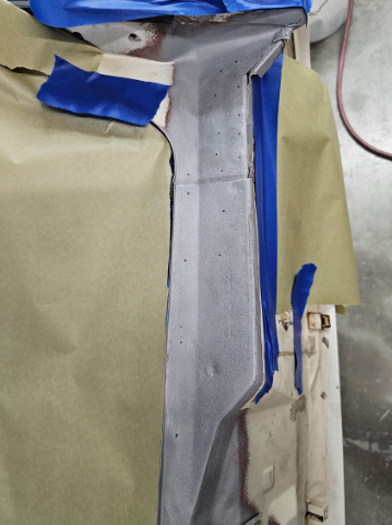
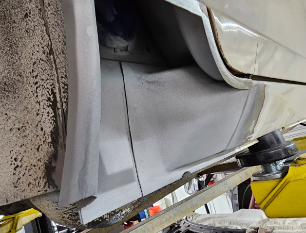
Then blasted the entire cross member and powder coated it in a super black semi gloss powder coat. Powder coated the motor mounts as well
I always first do a primer powder coat that is sandable
I sand most off this off to fill the small blemeshes
Then final coat
Finally the brushed stainless plate for the floor jack
Next up is getting a new transmission, then finishing the exhaust