
MONZTER
-
Posts
818 -
Joined
-
Last visited
-
Days Won
17
Content Type
Profiles
Forums
Blogs
Events
Gallery
Downloads
Store
Posts posted by MONZTER
-
-
Here are some final assembly pics of the NA car Rear brakes.
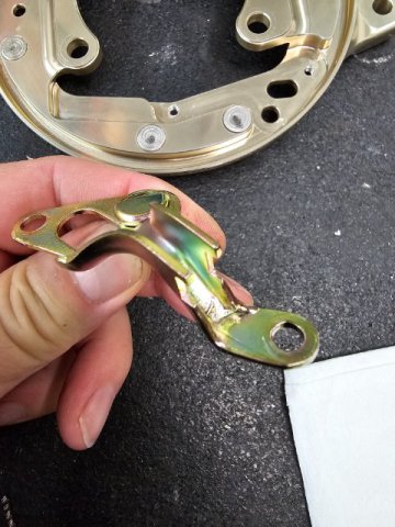
I had to take the OEM Z31 backing plate and cut the spot rivets holding this parking brake cable guide on. I then had to shorten it and weld on a new front mounting point. I ground the welds all nice so it looked OEM and then replated it in Yellow Zink. In the second picture you can see where I press fit in some stainless steel rivots, just sitting proud of the surface. This is where the "feet" on the parking brake shoes hit, and a little dab of grease should keep them smooth and quiet without worry of wear on the aliminum

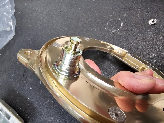
I next had to make a custom boss that will screw in to the new backing plate. This is the pivot and load point for the parking brake shoes. So I turned it out of 4140 steel, Yellow Zink plated it and threaded it into the backing plate with Red Loctite.
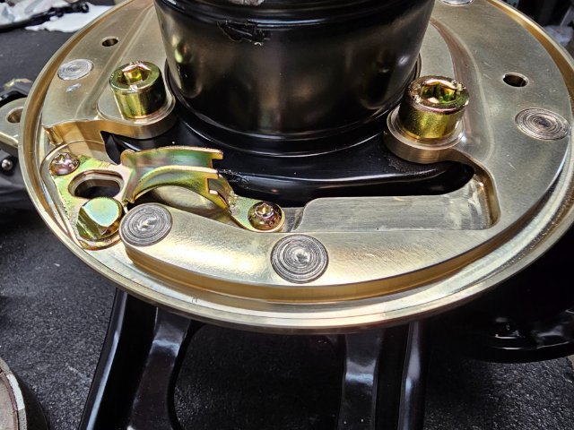
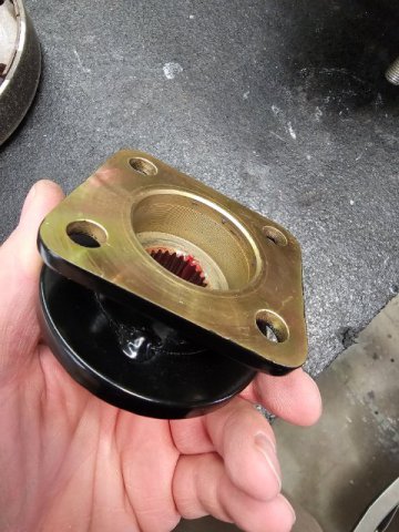
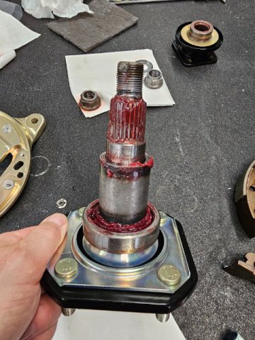
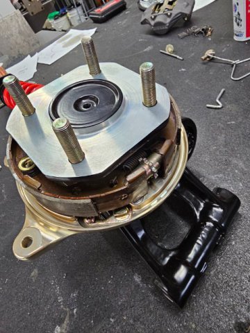
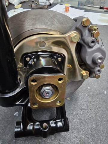
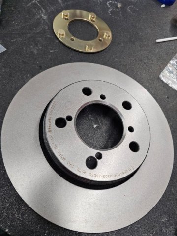
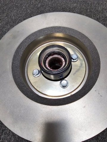
Then I could re-assemble the stub axle and companion flange. These parts came out nice with a Zink plating on all the mating surfaces and powder-coating everywhere else. They should stay nice for a while.
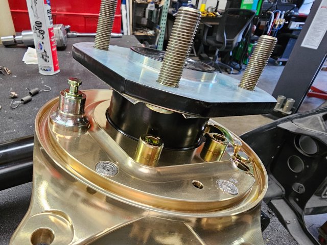
You can see the mounting bolts for the new backing pates.
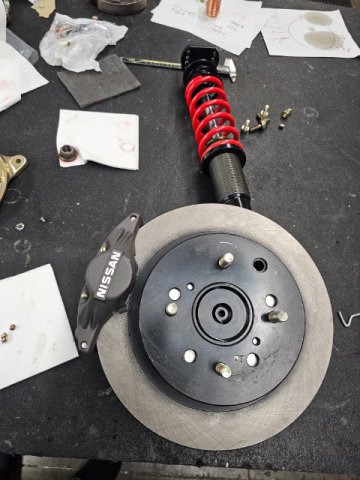
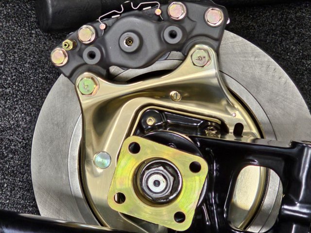
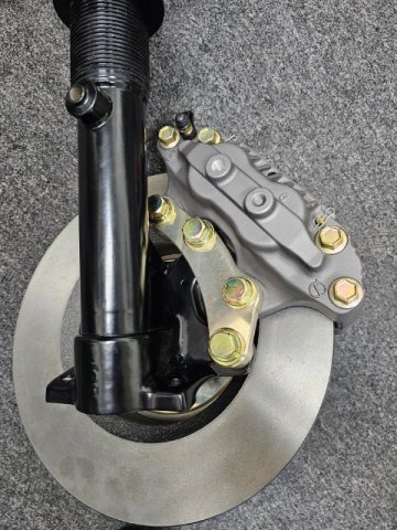
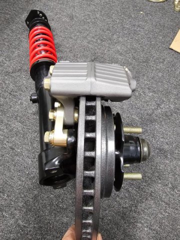
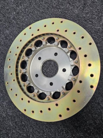
This is what the caliper looks like mounted with the Z-31 rotor
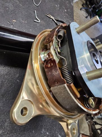
Installed the parking brake shoes, springs, adjusters, ect. All fit up just like OEM
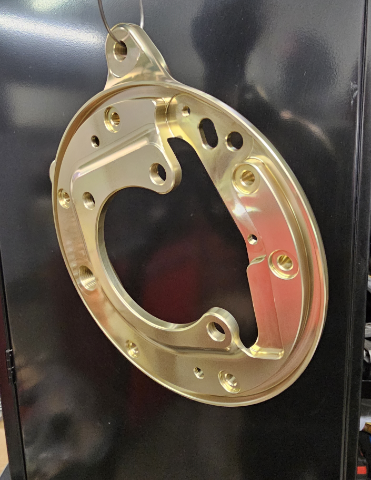
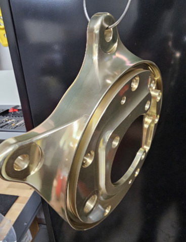
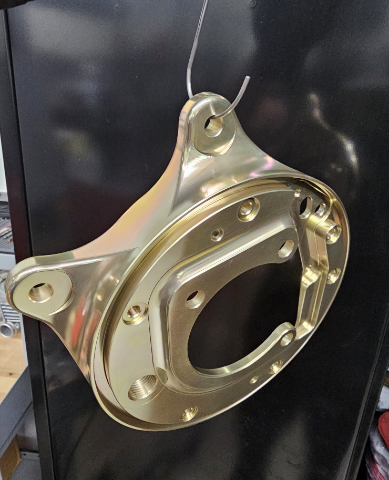
Some final shots of the plates all assembled. I think they came out looking cool, kinda morphing from the struts hub shape to the mounting ears of the calipers. The look will be very clean IMO
-
 1
1
-
-
Those look nice, whats you plan for MAP sensor, Brake booster, ect. Are you going to build a "log" to tie all the cylinders together?
-
Finally finished both L&R of the new rear Backing plates for the NA car. These are adapters that allow me to use a Z31 parking brake system and z31 rotor with Z32 aluminum 2 piston calipers and bolt it all on to a stock 240z strut. Yep it all works. For fun I took some pics of the machining steps to show what it took to make them from billet and finish them up.
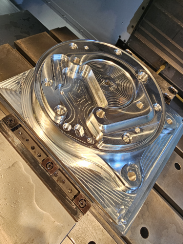
This is the first operation that mills the side to mount all the parking brake shoes and hardware. Comes out of a 8"x8.5"x2" thick piece of billet.
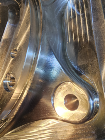
Some detail of the surface machining and stepover of the cutting tool to make for a smooth finish
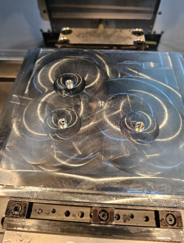
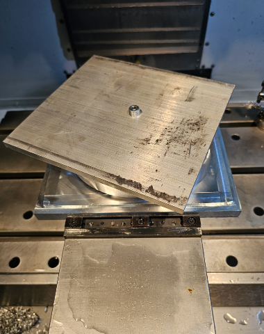
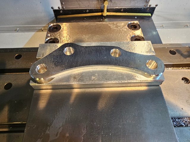
After the first operation is complete the part needs to be flipped and held to machine the backside. I made a simple fixture plate that held the part by registered with 3 mounting holes and a single center screw to hold it down. This is the fixture plate.
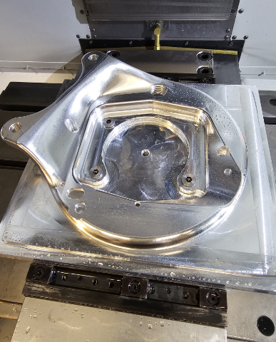
And this is the part after the first OP held tot he fixture plate ready to machine the second OP
This is the part after the second aoperation is complete. About 2 hours of run time. You could go faster, but I wanted small step-over lines so it would not need any hand finishing
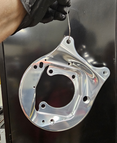
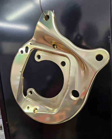
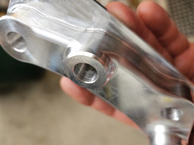
After washing it and prepping it for a Alodine finish, here is the part as machined
Final finish is a 5 second dip in the Alodine which gives it a goldish iridescent finish, then I sprayed it with a clear Cerakote to keep it looking good and easy cleaning
And this is the final part. Next need to make a few small parts and the parking brake cable
-
5 hours ago, Derek said:
Nice work.
There is something satisfying for me in designing something in a solid modeling program and then walking out to the shop and actually bringing it to life.
Or throwing it in the scrap bin because you had a better idea while machining it and decided to start over:)
I agree, I like looking at a chunk of billet and thinking anything I can imagine is in there, I just need to figure out how to get to it.
-
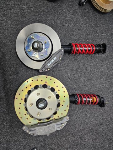
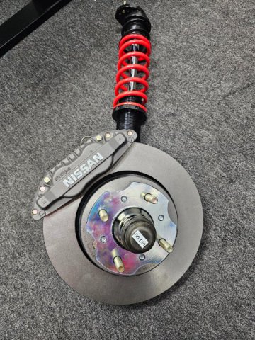
And some final shots of the assembly, along with a comparison to the Turbo car set-up shown previously

-
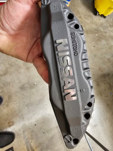
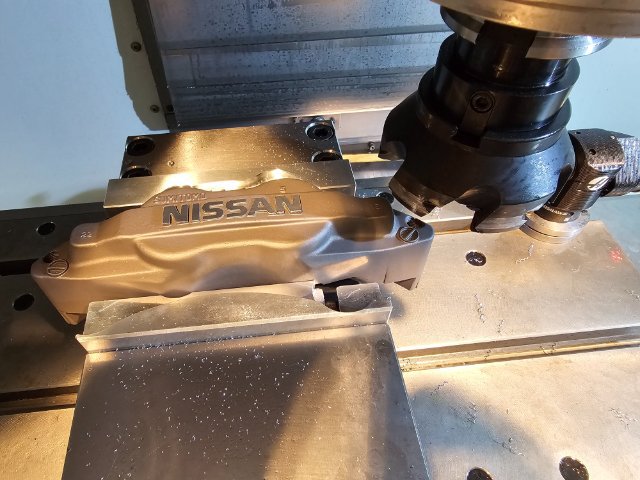
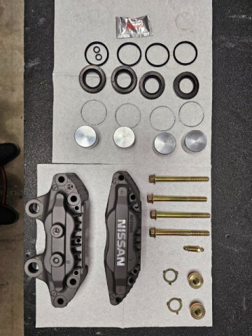
Here are some pics of the calipers I got from Ebay Japan. I ended up doing a complete rebuild with a nice Tungsten grey Cerakote finish and post machined Nissan logo. New pistons, seals and all freshly replated hardware with Stop-Tech pads
-
For the NA car I decided to go with Z-32 calipers, the nice aluminum ones for 30mm rotors with the Nissan Logo on them.
I did some research and saw many people were using a Honda rotor with a caliper adapter, so this was my initial direction.
Since I’m making everything myself I figured I would make these as well and started modeling it up in Solidworks. I started to notice some issues given the size of the Honda rotor. It looked as if the pads would interfere with the original caliper mounting point on the strut, possible causing the pad to bind. So I went a different direction and after scouring for drawings and modeling up different rotors I found a rotor from a Jeep Rubicon to be perfect.
It was a little bigger at 302mm vs 296 for the Honda part. This offset he caliper just enough to keep the inner pad away from the strut/caliper mounting point.
So I designed it in Solidworks and 3D printed a rotor and caliper adapter bracket to test fit the Z-32 caliper. After dialing it in for a perfect fit I went and CNC machined them. Finishing the adapter brackets in a Alodine finish with a clear Cerakote to keep them looking nice.
The Rubicon rotors were available in Brembos premium line of OEM rotors with a nice anti-corrosion coating and big open venting.
Because they had to be re-drilled for the Datsun bolt circle and the ID opened up, tooling was needed to get them all perfect.
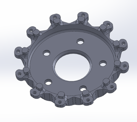
I even went as far as designing an adapter plate for the inside of the rotor to fill in the original holes and provide a nice clamping surface for the hardware
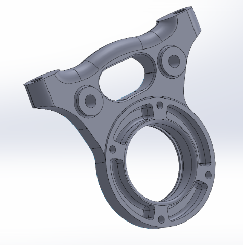
Pics below of the adapter bracket and some steps of machining it on the CNC, also the 3d part vs the machined part
-
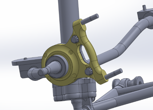
Some of the CAD models I built to make sure all fits as well as the models needed for the CNC work
-
1
-
-
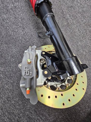
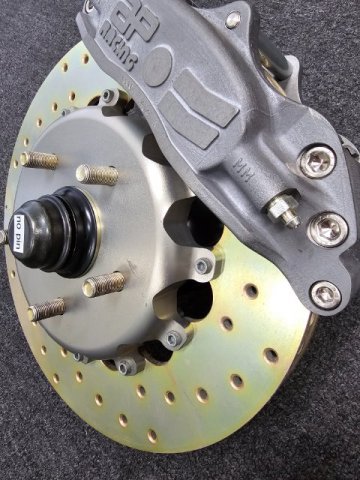
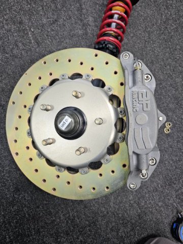
Again going with AP, the front rotors are 325mm vented and drilled with custom 7075 hats I designed and build to make it all line up. Im super happy with the way it all came out but a little over the top for a 2200lb car
-
Just finished up on the front brakes for both cars. In the typical way I have been developing parts for both cars, the Turbo car will get the over the top treatment and the NA car will continue with heavily modified but OEM looking components.
Since both cars will be using 16” wheels – SSR/Watanabe RS8s for the Turbo car and Panasports for the NA I wanted to keep the brakes fitting withing the 16” rim limit.
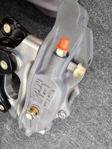
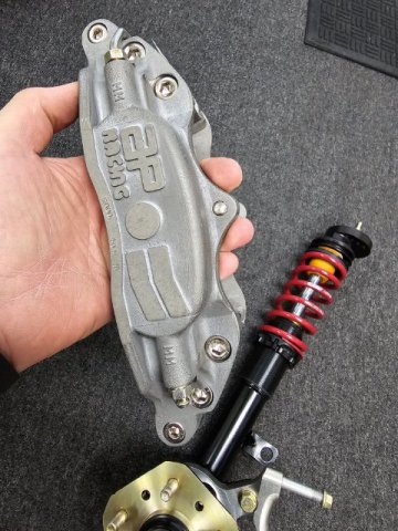
Having the ability to build whatever I want for adapters the Turbo car is getting AP 4 piston calipers CP5000-42S4 - It’s a racing caliper and surprisingly light given how big they are. One of the benefits is the radial mounting, which makes more a low profile caliper and allow for larger 325mm AP rotors to be used and still fit in the 16” RS8s
Here are some pics of the front calipers and adapters
-
Next up on the list of things to do it the strut housings. Both cars will use coil overs and have already been cut for previous struts cartridges. The NA car had Tokico BZ 3099 struts and the turbo car had Bilstein P30-0032 re-valved 300/100. Both now unobtanium
I had problems with the Tokico struts blowing up with stiffer springs and the Bilsteins were a bit much on the street.
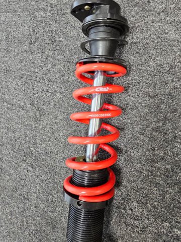
So I decided to go with Konis
- The 8641 1198Sport for the NA car with 300 pound springs front and rear
- The 8610 1437Race for the Turbo car with 300 pound springs front and 325 rear
Getting the ride height correct with the droop travel is important so I cut the front struts to 340mm measured from the bottom inside of the strut housing to the top of the threads and cut the rears to 380mm measured the same way. The fronts will drop right in with no spacers but the rears need to have a spacer made to go underneath the strut cartridge to get them in the correct location.
Both cars will get biscuit style camber plates from DP Racing as I won’t be changing camber all the time and I could not bring myself to cutting the bodies
I thought I took pictures of the struts and spacers before I assembled them, but I can’t find the pics. So only shots of the finished assemblies
Pics to follow soon:
-
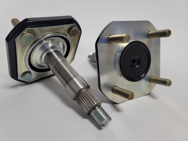
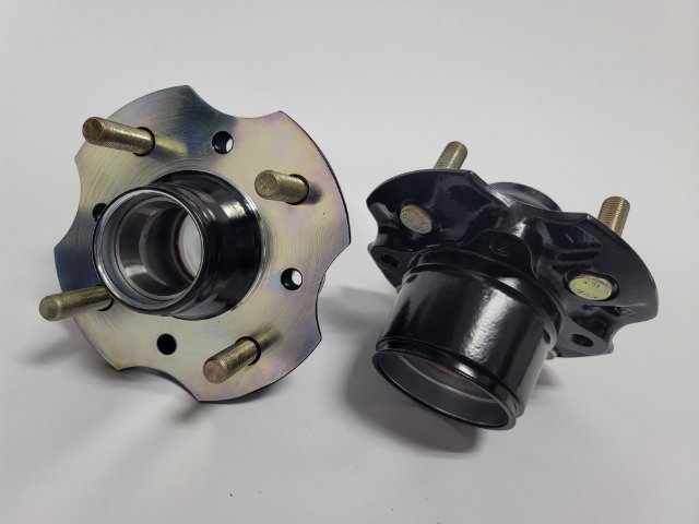
And these are the front hubs from the Turbo Car. Again Z-31 Turbo parts with 5 lugs. The extra offset let me integrate the new brake mount adapters to act as a labyrinth seal for the hub bearings
-
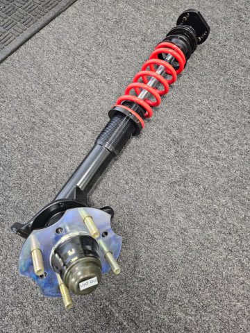
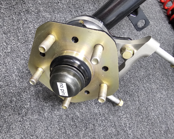
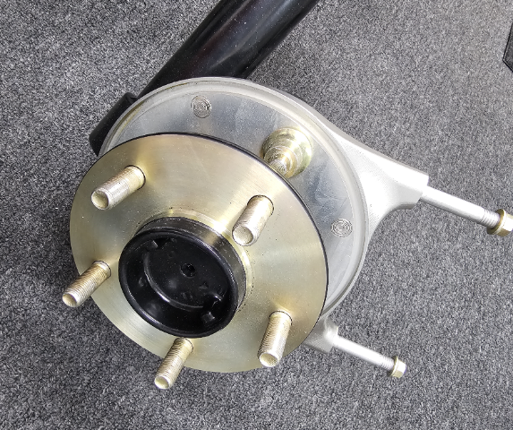
Here are some pics of the actual strut assemblies for the Turbo car. You can see on the rear how nice the Z-31 hub, bearings and stub axle integrated into the 240 strut as well as looking proper with CV flange.
-
The NA car is using stock rear axles and the stock front hubs with 4 lugs and has been fine considering the 235HP of the L-24 motor. However, the Turbo car will have most likely double this HP and everything needs to get beefed up. I handled this in an interesting way as I like to try and keep everything looking OEM and even using OEM parts when possible. Far from stock, but stock looking.
My idea was to use all Z-31 Turbo parts to not only get the beefier stub axles and 5 lug hubs, but to also change the hub offset on the car so that it would use 25mm offset wheels the same as the Z-31 Turbo car.
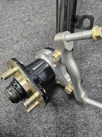
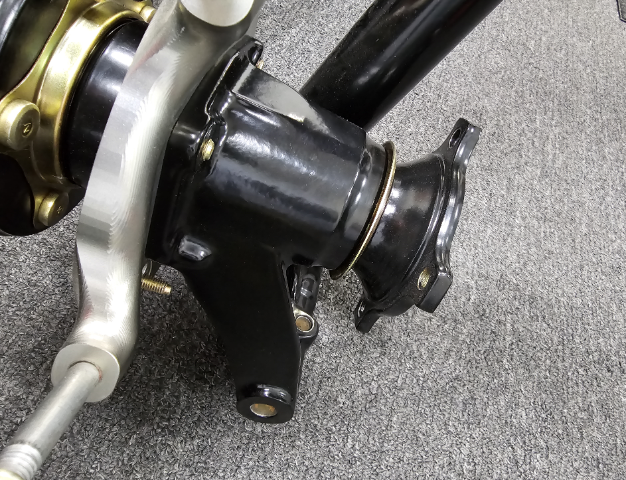
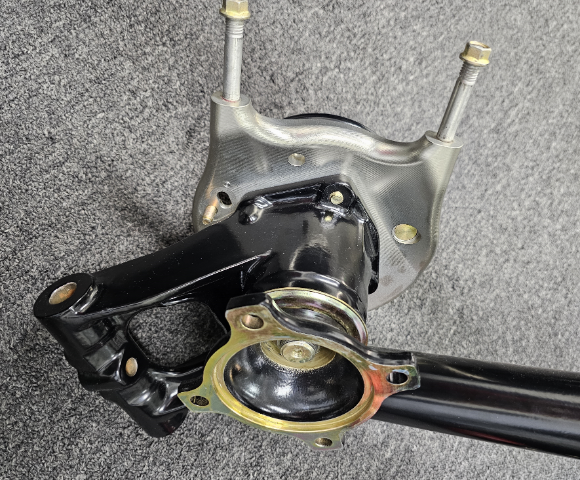
I accomplished this by literally cutting off the rear axle hub from a Z-31 control arm, turning down the diameter to remove the weld and inserting it into the 240z strut after boring out the step for the smaller 240 bearing. Press fit it in and did a perimeter weld all the way around. Now I could use a OEM Z-32 axle, bearings, spacers CV flange ect.
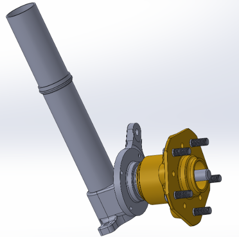
This is what it looks like after cutting it off and turning down the weld. The diameter is near exact to fit in the 240z strut. I mocked it all up in CAD first.
The outer bearings and diameter of the axle is considerably larger than the 240. Here is a cross section of it installed into the 240z strut
I thought I had some other pics of them before I finished them up, but I could not find them
For the front hub I also used a Z-31 Turbo hub. It actually bolts right on with only minor cutting of the outer lip of the grease seal. So again 5 lug and the same offset wheels as a Z-31.
-
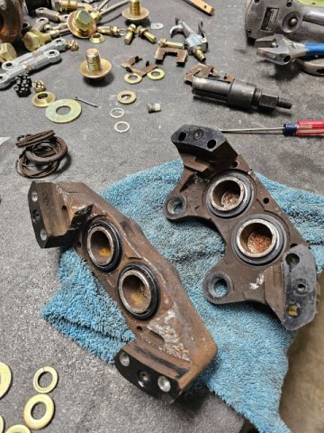
When I finished up the Turbo headers is when I got the bug to really get back into these projects. One of the areas I first wanted to focus on was the suspension. Having a lift made it a good place to start as I can pull the suspension from the NA car and refurbish it, while I completed some of the additional parts I still needed to finish up on the Turbo car. It makes things easier for fabrication and restoration when you do more than one part at a time. So I started the suspension on both cars.
The hubs are an area that always bugs me as they get rusty and beat up quick, especially on the mounting surface to the wheel. I have my own Zinc plating system and Powder Coating, as I got tired of the companies here in California upping their minimum lot charge into the hundreds, Plus most of them won’t touch car parts for fear of contaminating the tanks they use for Aerospace. Now that I can do it myself I had an idea. Typically if you had a part with areas you did not want plated or powder coated you would have to use special masking techniques, like a liquid masking for plating or high temp tape for powder. It’s an extra upcharge and the quality of the masking can be questionable.
So I tried a different approach. I first blasted and prepped the hubs and rear axles for powder, taping and plugging them myself as needed, then coating all surfaces of the hub and the complete flange area of the rear axles. After the powder coating I fixtured the hubs in my lathe and carefully turned the powder coat off of the mating surfaces. Now this make the flanges nice and straight and flat, but also susceptible to rust. So next I put them in my plating tank, with remaining powder coat acting as a masking so the zinc wont stick to it. The zinc only plated the freshly machined faces. After this a gave them a Blue chromate bath to seal the zinc and provide great rust protection. Finished them up with new studs and replated the labyrinth seal plate on the rear axles. I ended up with nice powder coat super tight plating to powder lines and perfectly flat and true mounting faces.
The NA car is staying 4 bolt stock hubs and axles, the Turbo not so easy. Ill post them up tomorrow
-
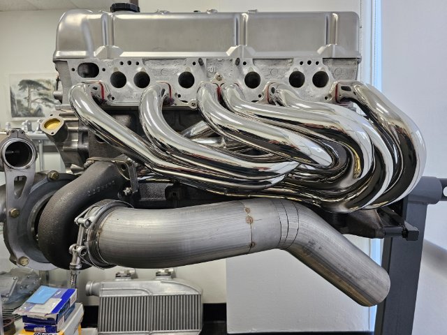
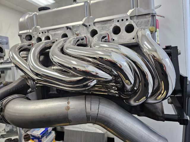
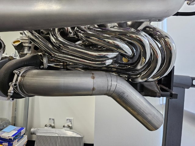
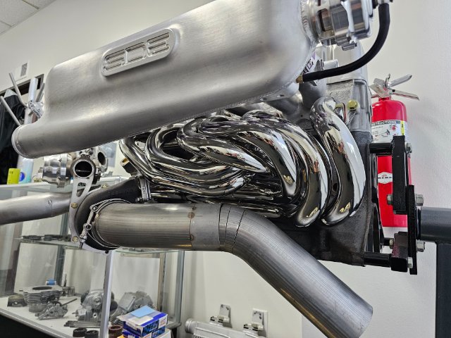
Mine has been sitting here in my office as a display with the rest of the engine. About 6 months ago the first part I started on completing was the long tube headers for the turbo car. I always liked the "bag of snakes" look from the old Gurney car, so this is what I ended up with. It’s all 321 stainless. Probably about 6 hours of sanding and smoothing on each primary, then I sent it out to polish which cost a small fortune to polish.
Its a 6-2-1 design with 28" primaries in 1-5/8 diameter. Obviously the down pipe is just a mock up but its 3.5" diameter. I will run the wastegate parallel along the down pipe and connect it in downstream
Some more pics
-
2
-
-
4 hours ago, Dat73z said:
Apparently you can pre-order them here: https://milkfab-engineering.com/shop/ols/products/milkfab-l6-ultimate-intake-manifold?fbclid=IwAR2QU6NWyno4bkaHjMeclJE8GjibiUpXNflrK7zKtNn78XIMtKwqNsuRALg
It would've been cool if they had a standard dcoe style pattern for the runners to open up itb options.
Also I just realized in the description you inspired the design so I suppose that makes sense 😅
Thats looks pretty cool, seems to pretty much capture the design intent. It will be interesting if they finish it up and see some results of how it runs vs a stock system.
-
5 hours ago, Dat73z said:
That plenum is a work of art. Have you seen the Milkfab engineering plenum? It looks like they're working on something similar, but I think your design looks much cleaner.
I thought I heard about them going out of business? Who else make a plenum that is available to purchase for the L-Series motor?
-
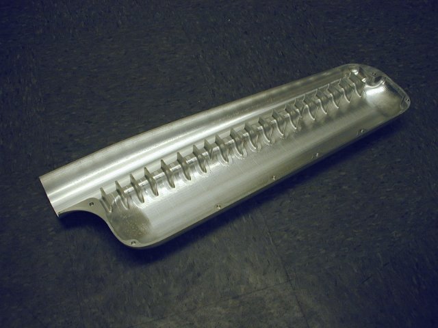
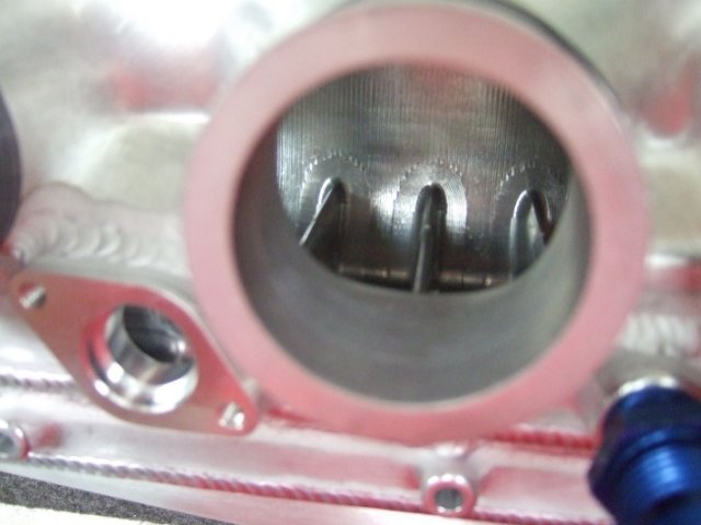
Here are some pics of the Turbo Plenum showing the inside details of the slot and the flow straightening vanes to prevent swirl as the air changes direction. These vanes gave the air more of a tumble into the runners for even flow. I see if I can find some of the old CFD pics on a back-up drive somewhere.
-
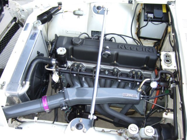
This is the NA Plenum. I found a OEM verion that did not have the EGR and proceeded to cut it up. Cut the plenum down the middle to open up and blend in the runners. Added about an inch to the width to increase the volume. I then added about 1.5 inches to theh length of it where the throttle body attaches. I added this at an angle to better align it with the front cowl for a straight pipe, as well as allow for a large radius. I think the angle and the large radius going into #1 was a good way to go. Ill try to find more pics of it before it was done showing the work.
-
I only ran simulations (CFD) on the Turbo Plenum. As for the NA Plenum, I used a stock version and modified it myself. Personally, I don't think it's as necessary for an NA car since it pulls in air instead of being pushed like a Turbo. But hey, that's just my initial thinking. The dual plenum design might help reduce turbulence in an NA car, but we'd need to put it on a dyno to know for sure. Unfortunately, CFD would be tricky for that. I could try some ideas, but I don't have access to the software anymore. Right now, I only have access to basic fluid software in Solidworks, and it's not great for modeling air and other compressible fluids.
Ill dig up some old photos and post them up of both of them since it sounds like many of the original photosd are gone.
-
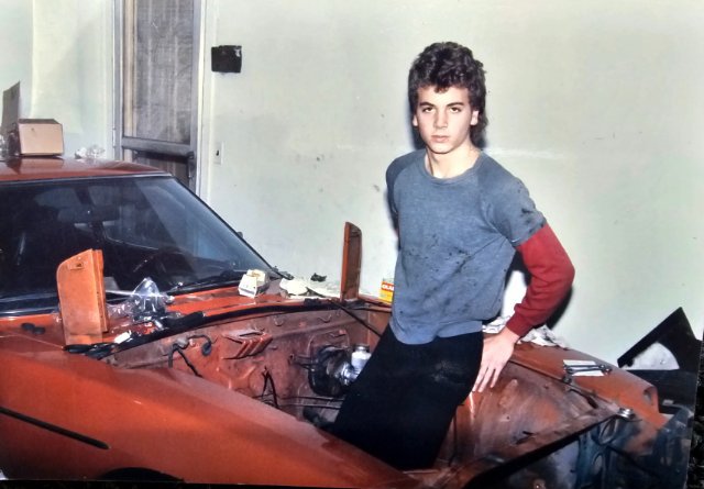
I've owned what will be the turbo car since 1984 (black shell now), which is pretty cool. I bought it in Atlanta, Georgia, so it was in great shape with its original paint and no rust.
I still remember the first time I laid eyes on a 240z. I was 14 and working at a bike shop. One of my co-worker's friends had a shiny black one, and I instantly fell in love with it. I saved up around $1,500 over the course of a year. Living in Ohio meant finding a clean, rust-free 240z was a challenge due to all the salt on the roads during winter.
Luckily, my dad knew someone who bought cars down south and sold them in the rust belt. I asked him to keep an eye out for an original and clean car for me, and after a few months, he found one. My dad and I flew to Atlanta together, and I even got to drive it back home on my learner's permit. Those were some really great memories.
Here are some old pics I found digging throug boxes
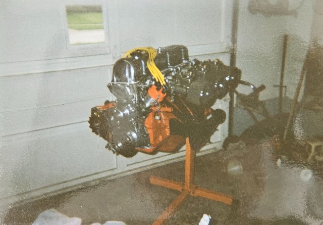
Me ripping out the engine as soon as I got it. I had a shop class in high school where we re-built a lawn mower engine. This this was my first car engine I ever built. I remember reading the "How to Modify" book over and over. Who did not want that engine on the cover in their dream car? Drove it like this throughout High School.
-
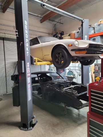
This is both cars as they currently sit. The Turbo car is the black shell. All apart and ready to be put back together. The white one on the lift will be the NA car and its just starting to come apart.
-
I have two cars Im working on, one is a NA car and the other one will be a turbo car. Im having a race against myself which one will be finished up first. It will also be fun to compare the differances between the two.


.jpg.198e8545123739c7490db26c4fae6a66.jpg)
.jpg.0043d967ed26652065eaa04f275a1dbb.jpg)

1971 240z ITB install
in Nissan L6 Forum
Posted · Edited by MONZTER
Ahhh, I thought you were programming and maching it, I was going to say nice work, not an easy part to program. Are you paying them based off 1 part? I assume the time to program and tool is a bigger expense than machine time?
I'm in the same boat, I wish I could find a nice set-up for my NA car but nothing makes me happy. I might have to make one myself as well.