

mattb3562
-
Posts
161 -
Joined
-
Last visited
Content Type
Profiles
Forums
Blogs
Events
Gallery
Downloads
Store
Posts posted by mattb3562
-
-
There is also plenty of wall thickness in the manifold to remove 3/16". While in the process, I would also wrap it and blanket the turbo. You will be glad you did while you're at it instead of later.
-
Yes should be able to adjust trigger angle enough. I've only read that you shouldn't have to go below 50. I believe what you're doing by setting the trigger angle is telling MS how many degrees BTDC your crank actually is
-
After checking that it holds the commanded timing thru revs, I locked the dizzy.
-
I personally just set my dizzy 'hand tight' in the center of adjustment when setting base timing. Also, yes setting a +10 degree advance is probably the easiest wqy to set it. I started with a 60° crank angle. It was flashing around 0, so I went to 50° angle and it showed 10° advance on the light.
-
Tunerpike, you need to adjust your trigger angle in the spark settings until your light is flashing the commanded timing from Tuner studio. (So if your fixed advance is set at 10°, adjust your trigger angle until its flashing 10 with a timing light.)
-
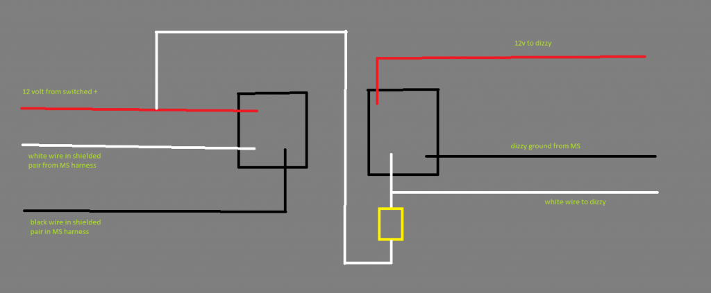
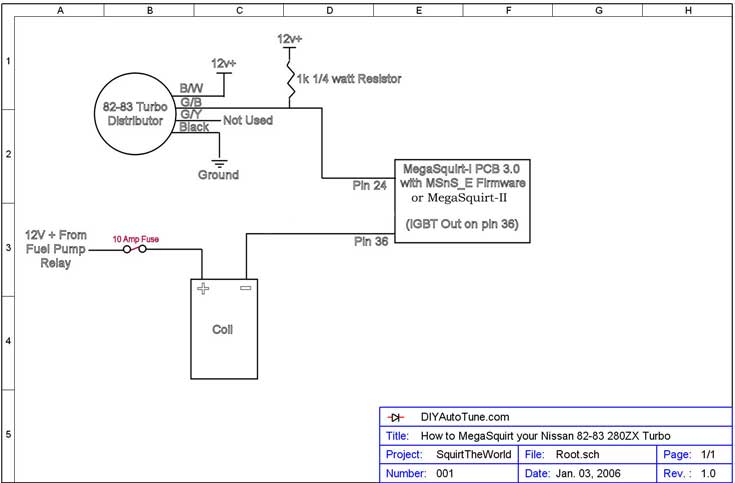
I forgot to label it, but the yellow square in that diagram is a 1k 1/4 watt resistor
-
Alright, the reman dizzy I bought from Advance did work for me and got my engine running. I set it to an 18 degrees fixed advance and set the base timing. It all worked out well and showed the 18 that was commanded through the rpm range. All was well. A few days later while working on some other bugs with the car, the engine went back to doing the same thing. No crank trigger. No square wave from the dizzy. I got them to replace the distributor that I bought with another one and it fired right up. That has worked well for the last couple of weeks, only being cranked less than ten times, and it quit on me again Thursday. What I'm trying to figure out is if there's something I've done to cause these to go out or if they're just junk. Here is my diagram to how I have it wired. I used a 4 pin Denso connector to the dizzy with everything nicely soldered and heatshrinked. For 12v, I have a main relay taking constant power and a switched 12v signal from an unplugged efi connector on my 76's harness under the steering column. That relay sends power to a 6 way fuse block that sends independent circuits to the Megasquirt, coil, injectors, and distributor. Grounding is a 4ga running from battery to bellhousing and a 10ga from battery to firewall. I've ran a 12ga from battery to firewall on driver's side that connects all of my ecu grounds in the same place. I ran all of the sensor grounds to the sensor ground wire in DIY harness. My plan is to strap the body to engine with another 4ga to tie it all together. Also may run an independent gound to the dizzy black wire instead of just relying on the shielded black wire in the DIY harness. I was hoping to keep out noise by grounding to the shielded wire.
However, I honestly don't believe it's something in my wiring because it was working well and showing good triggers before it quits. Any opinions are greatly appreciated.
-
Advance had a rotor in stock for my turbo dizzy. A cap took a couple days
-
I'm sorry to be sidetracked, but what are those lights out of Redlinevo? Badass!
-
I just thought that I'd throw this out there a couple weeks before ordering a new one. I'm ready to purchase a wideband setup if anyone has one that they'd like to sale. I'm really looking at the AEM, as it seems to be the best price from a great company and so many people seem to be having trouble with their Innovate setup. But I'd consider any one of them. Thanks fellas.
-
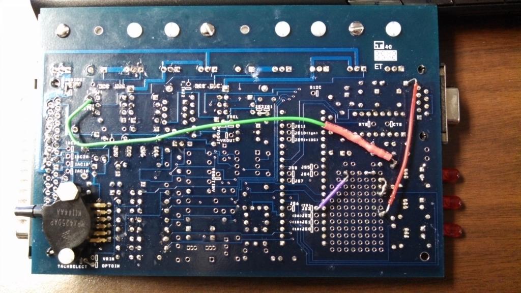
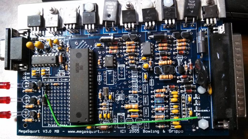
Yeah, that's what I'm doing. Basically, all it's doing is taking the 'on/off' signal from the CAS and sending a trigger to the coil to fire and an injection each time it triggers. Here's my board. Disreguard a couple of the jumpers to JS3. That's how I modded for a fan relay control. (Another reason I shoulda gone with MS2.) But you should be able to see the ignition output pretty well.
-
Mine is now working well, Heroe. I just followed the mega manual assembly instructions and then, went to the DIY site and modded for the l28et. I still haven't timed it, but it's fueling plenty right now on Cygnusx1's newest map and I've cranked it up with a set base timing of 10° and @ 18° advance. I need to round up a buddy to grab a timing light to fine tune the base timing, but it shows exactly as commanded. I prolly just need to adjust the trigger angle some. But here's a success story for ya.. I had never soldered on a board nor did I buy the stem for the MS. I checked voltages and grounds as I went and checked the communication with my laptop before I hooked it up and all was good. The only major hangup I had was loading the MSExtra firmware on the board with Windows 7, but you won't have to worry about that anyway. I'm just figuring the tuning part out, so I'm right there with ya! Lol
-
In AL, a written quote can vary up to 30% of charged price. With that being said, I would only use a well known and established business. There are some people who do really good work, but the only way you'll be guaranteed is by dealing with a certified shop. I have 11 years experience in this business. Here in Al, what you're needing could be done nicely for around $4500.
-
Well, an update for those in the future with a similar problem....a bad CAS was causing my ignition woes. It was send an inconsistent signal. It now cranks fairly easy. I have to hold slight throttle on it, but still haven't set base timing yet, but hope to have it running on a decent tune this weekend. And yes, the ms1 with the 029y4a firmware works well with TS 2.0.8
-
Yeah that's what I have done. Opened Tuner studio and manually entered all of the settings. Idk about the firmware compatibility, but all of the guage s are reading well on the software and the trigger logger showed me signal earlier and sparking well. I'm now thinking it's just needs timed
-
I uploaded Cygnusx1's map from this page. Its the GREAT!.zip file
-
I have a switched 12v wire running to red wire on dizzy and the shielded pair run with white wire out of pair to white wire on dizzy. One side of my 1k resistor is inline with this signal wire and the other side of the resistor runs back to 12v. (which for now is my power probe for troubleshooting). I first had the signal to resistor combo tying back to my switched 12v and it was doing the same as it is now with its dedicated 12v to each. Black wire out of the shielded pair is going to dizzy ground. I have also tried grounding dizzy to chassis and to engine with no luck.
I havn't been watching the ignition logger on Tunerstudio, but I will try that today. I have just been watching the tach on the guage cluster. It hardly and randomly tries to fire when the signal has a constant 12v on it, but when I manually pulse a signal, it will try something. Out of time, though, of course.
I'm using Cygnus's newest map on the map sharing section, as it is a very similar setup. However, he was using EDIS and I'm triggering a MSD coil directly, so that could be a variable....I actually havn't seen in Tunerstudio where to change to 'standard coil charge' as it shows in Megatune. I don't think that would keep the engine from starting, though. The ecu does seem to be doing what it's supposed to when it gets a signal, though. I get an LED and it triggers the coil to spark.
-
After some troubleshooting yesterday evening, I believe I've come to the conclusion to have a bad CAS inside the distributor. The thing that's really unnerving is that there seems to be NO TEST PROCEDURE IN THE FSM. In the desciption it says it releases simply an "on/off" signal at 120 degrees. I am getting a square wave out of it going from continuity to ground, but it seems the MS is wanting a positive voltage signal to fire. I am using my power probe to power up the signal wire through the 1k resistor and holding 12v on the white wire, every now and again it will send a signal to the ecu and MS will fire the coil. Very intermitently. For those of you familiar with a power probe, I can hit the button rapidly to supply 12v pulses to the signal wire, and it will spit and sputter like it's wanting to start. There, I get a triggering LED on the ecu. I hate just replacing parts so does this theory sound right to yall? It looks like a 0-12v or a 0-5v pattern coming out of the dizzy at the proper timing would be exactly what it needs. Thanks alot for any thoughts.
-
I coulda swore I seen your email address on the DIY site once, but didn't find it. Anyway, here are some bigger pics.
-
I will send some that are huge to your email address on the DIY website. I appreciate it.
-
Well, it's been a long road to turbodom, but I finally everything together to get my engine started on MS1v3 this past weekend. After a couple leaks fixed and about 4 hrs of wiring, she turned over smooth, but did not fire. Connected to Tunerstudio, all guages were reading except the tach on Tunerstudio. I was by myself, so I could not hold the coil wire to ground to check spark, but I would safely assume there is none. I have just took a good look over the ecu board that I built and all connections/solders look good to me. I double checked over the high current coil driver instructions on the Megamanual assembly site and modifications to the board from the DIY site on installing for l28et site, and all looks well. I'm wondering what the bip373 should show on the three legs while powered up. Also, my other theory is that the way I wired the CAS is with 12v going to the dizzy and the signal wired to the 1k resistor and tied back to the 12v constant on the dizzy. This may be knocking my dizzy power back down thru the resisitor? This evening I'm gonna run my signal back to battery 12v thru the 1k resistor and see if that fixes it. Any thoughts? Also, here is some screenshots of my board, if anyone sees anything I'm missing.
-
So.....just to be absolutely sure....I can run a
12v supply to red
White wire out of shielded pair to white
Solder in 1k in the white wire and tie back into red
And tie black wire from dizzy to shielding and run both to chassis ground?
All this and not use black wire in twisted pair or green from dizzy?
I really appreciate the help fellas, as I just wanna do it right before any major woes occur. Lol
-
Also, after doing some more digging, the fsm shows the colors on Moby's writeup to be right and mine to be other than factory. Maybe a replacement, I don't know. This guy had the same problem in 2005, that a few chimed in on,but doesn't show what came of it. Does this one ring a bell to anyone? ...Tony?... Help?
http://www.zcar.com/forum/10-70-83-tech-discussion-forum/105372-82-cas-sensor-wiring-megasquirt.html -
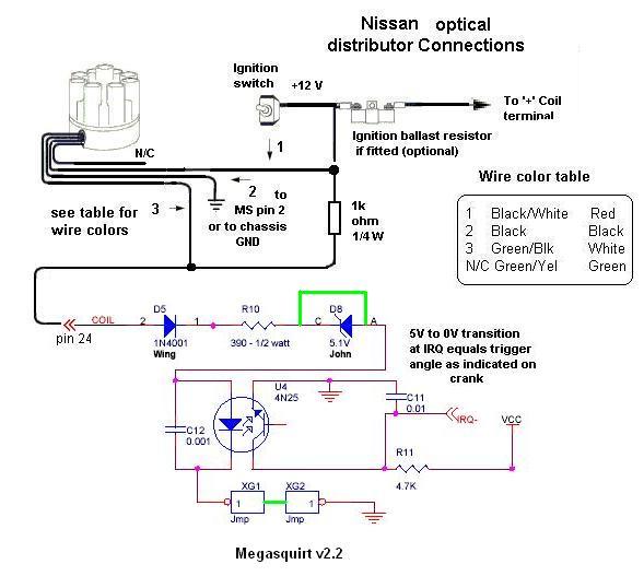
Sorry, I was in a fizz and forgot to insert the pics. Here's the diagrams that I was referring to...I'm sorry if this is a dumb question, but this part, I can't seem to put two and two together.


Another T3/T40e internal wastegate woe
in Turbo / Supercharger
Posted
Also, when you adjust your actuator rod, you're supposed to preload the waste gate. Screw it out to where it slips over the swing arm, and then back it up 2 rounds to where you have to slightly pull the actuator arm over the swingarm on the waste gate. This takes all the slack out of the operation.