Boben
-
Posts
401 -
Joined
-
Last visited
Content Type
Profiles
Forums
Blogs
Events
Gallery
Downloads
Store
Everything posted by Boben
-
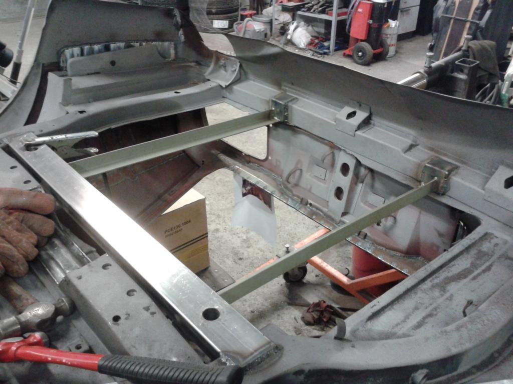
Found this picture from the web: Does anybody confess this being from their swap project and mayby guide me to a write-up on the subject? Anyways, this guy cut the frame rails and made some more room to assembly the engine lower. I was already pretty convinced that raising the tunnel would be the way to go, but then I saw this and talked to some mechanics design guys at work for initial design of the frame rail mod. If I were to modify the frame rails, I would cut a piece of the rail at the strut tower and add a similar rail structure bend from sheet metal to the wheel well side. The cutouts on the rails in the engine compartment would allow me to assemble the engine low enough not to require cutting the tunnel. The engine would be positioned close to the firewall so that the AC-compressor and the alternator would slip into the cutouts at the strut towers. The original x-member would be replaced by two x-members. one of these would be positioned in front of the cutout and the steering rack would attach to this from behind (opposed to the original placement in front of the x-member). The other x-member would be positioned behind the cutout. This one would include the engine mounts. The control arm attachment flanges would be cut out from the original x-member and welded straight to the new rail on the wheel well side. Any thoughts?
-
I have been trying to find information on other V8 swaps of whether people are able to preserve the transmission tunnel intact and still get the engine and transmission in without generating a huge angle difference in respect to the differential axle. In my understanding they should be in the same angle and there should be a slight parallel displacement to assure proper joint movement. Seems like in many cases the alternator is positioned quite high. Is there any other swaps that have been successfully finished, where the auxiliary devices of the engine are close to the longitudinal frame rails?
-
The M60 V8 is quite popular with the BMW E30 gang. I am not sure if these engines have been transplanted into other vehicles that much. This is the first attempt on a Z as far as I know.
-
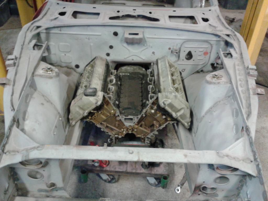
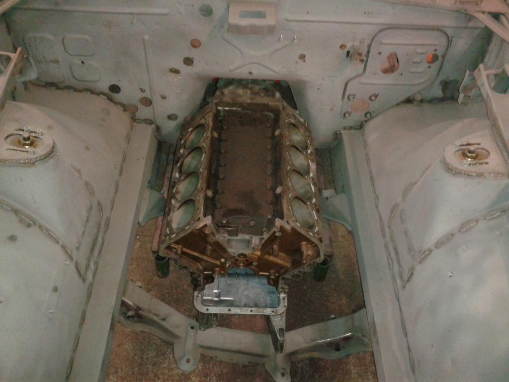
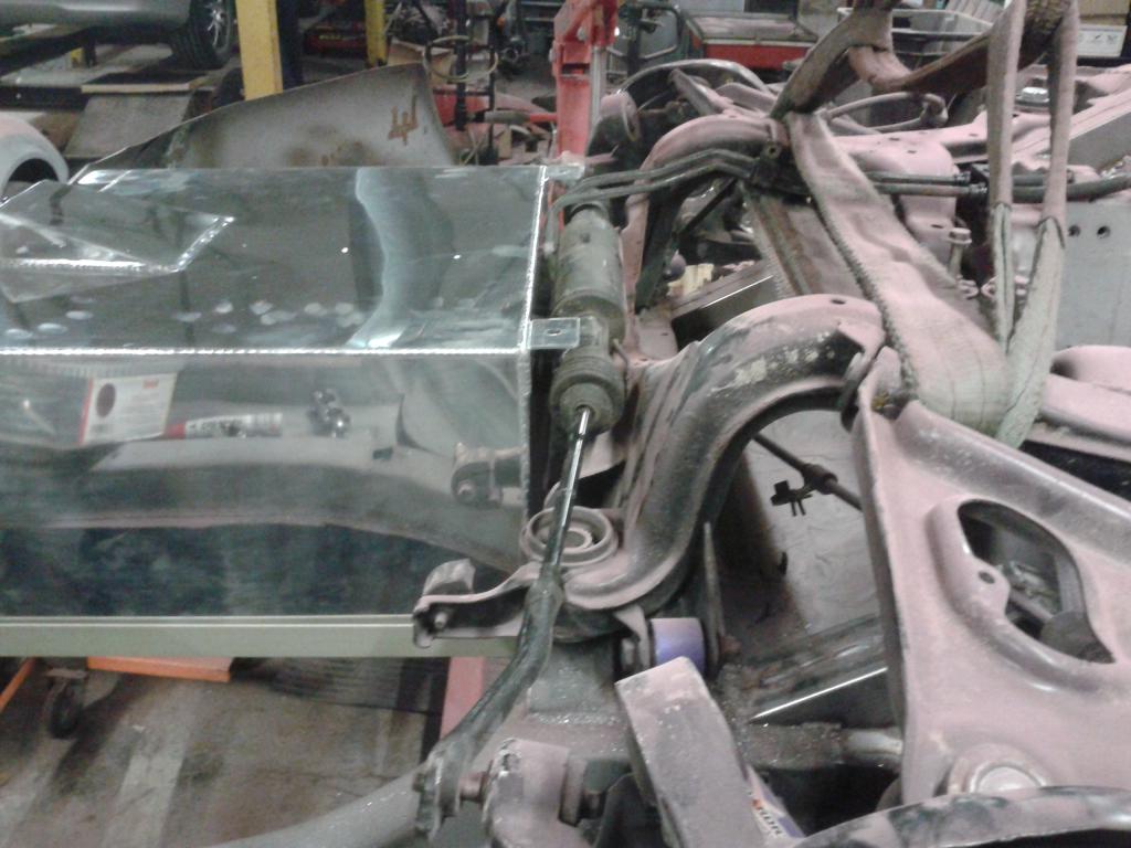
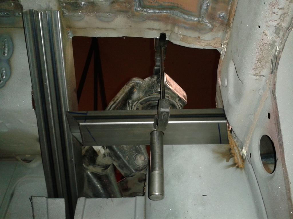
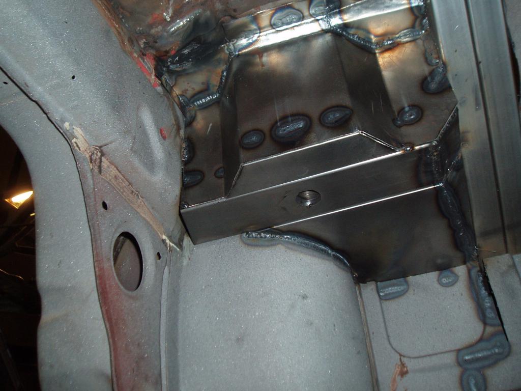
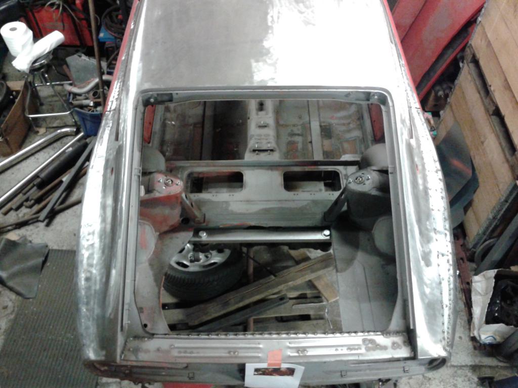
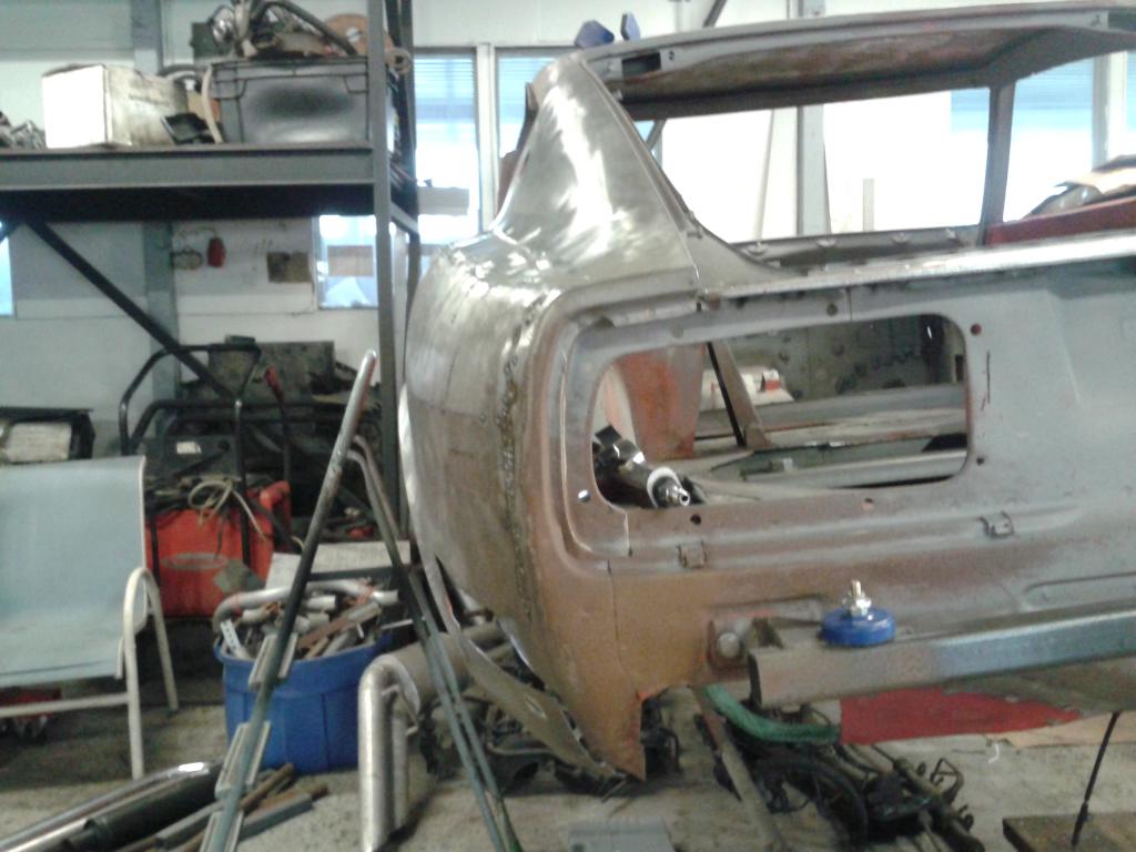
I Spend a few hours at the garage today. I found some cheap lazer alignment tools from the hardware store which I used to get the transmission axle and the differential axle to line up. Here the transmission axle is 30mm lower than the differential axle and the lines from the axles are aligned: This is how it looks from the engine compartment: The transmission is about 20 mm from the top of the transmission tunnel and the front cover of the has to be raised 50 mm in order to prevent the alternator housing from hitting the longitudinal frame rail. I figured my options are to cut the longitudinal rails just before the cross member and make a tube frame in the front or to raise the transmission tunnel 50 mm and shift the whole power plant 50 mm higher. I prefer raising the tunnel so I guess the Z is going under the knife once again. Obviously the HVAC unit (or what ever that is called in these old cars) will not fit to the narrower space after the mod, but it seems as though the unit can be modified to squeeze it into the space. there is approximately 20 mm free space under the unit and the space under the heat ex changer can be made narrower with still preserving some airflow. I don't know how good the ventilation to the foot well will be after the mod, but alot of the other problems associated to the engine mod will be solved.
-
Nice work there man! What transmission are you going to be using? have you checked the clearance to the top of the transmission tunnel with the engine mounted as you have it? I am just wondering because I am doing something similar, but with a BMW M62 engine combined with a Getrag 420G. If I want to leave the tunnel untouched, the engine needs to be mounted quite low.
-
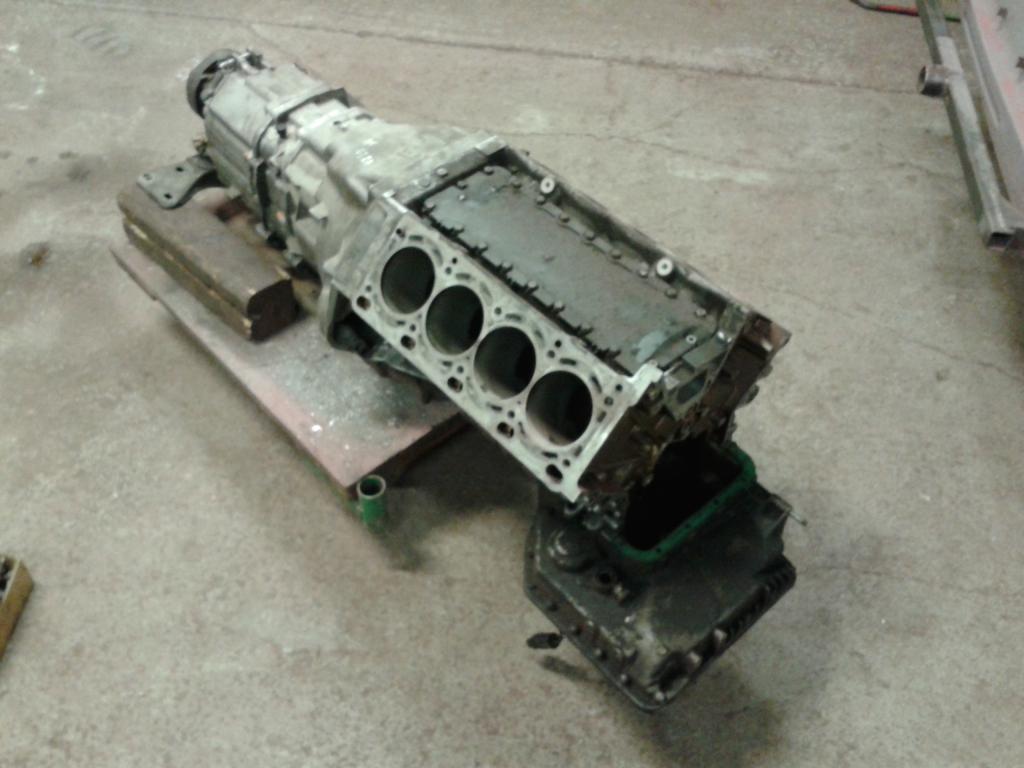
I am planning on installing a BMW M62 V8 engine into my 240Z and thought I would start a separate engine swap topic hear to get some feedback from other similar swaps. I found no reference of anybody doing this swap before, but I would guess there is some similarities to other DOHC headed V8 engines. My project topic can be found here: http://forums.hybridz.org/topic/120290-240z-egoboost-by-boben/ I assembled a mock-up engine with a Getrag 6-speed transmission to test fit the engine. The engine is missing the alternator and the AC-compressor, but it is pretty clear from the test fitment that there will be clearance issue to the longitudinal frame rails if the engine is placed as low as it is in my test setup. In the test setup, the engine and trans are set horizontally and the transmission is almost touching the sealing of the transmission tunnel. The fitment can be seen from the attached pictures along with a drawing of the M62 engine with all the auxiliary equipment.

-
As the work I am doing on the car at the moment is not so much body related, I decided to start a project topic which can be found here: http://forums.hybridz.org/topic/120290-240z-egoboost-by-boben/ I assembled the rear subframe along with all the attaching parts and started fiddling around with the engine and transmission fitment.
-
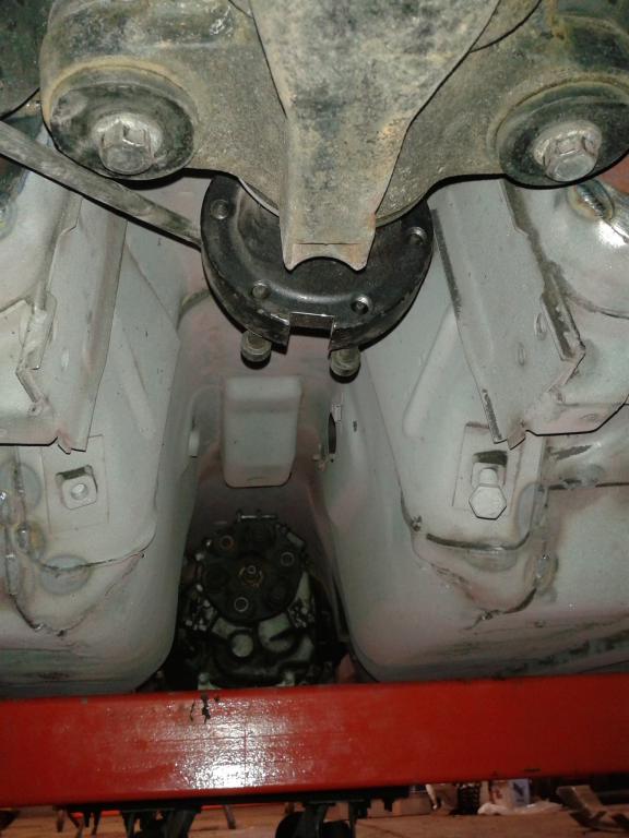
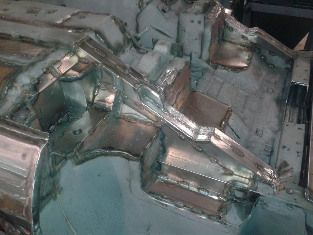
Finished up some welds from the interior side around the front fixing points of the GTR subframe. Then I assembled a mock-up engine with the transmission to test fit. The first idea was to use the oil pan found from 5-series BMW sedan, but unfortunately the cross member is just not going to clear. I replaced the oil pan with a part found from the BMW X5. The problem with the X5 oil pan is the height. When the engine is in place, the oil pan hangs lower than the cross member. Also, the X5 oil pan does not quite clear the cross member either. I need to assemble the mock-up a little further to really understand all the clearance issues.
-
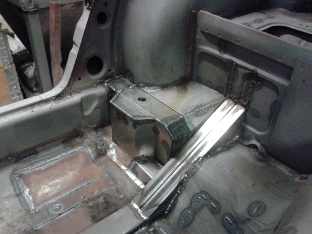
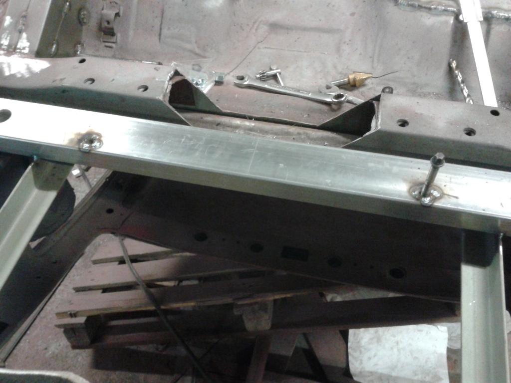
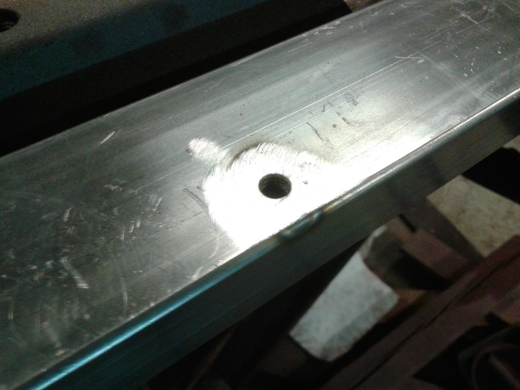
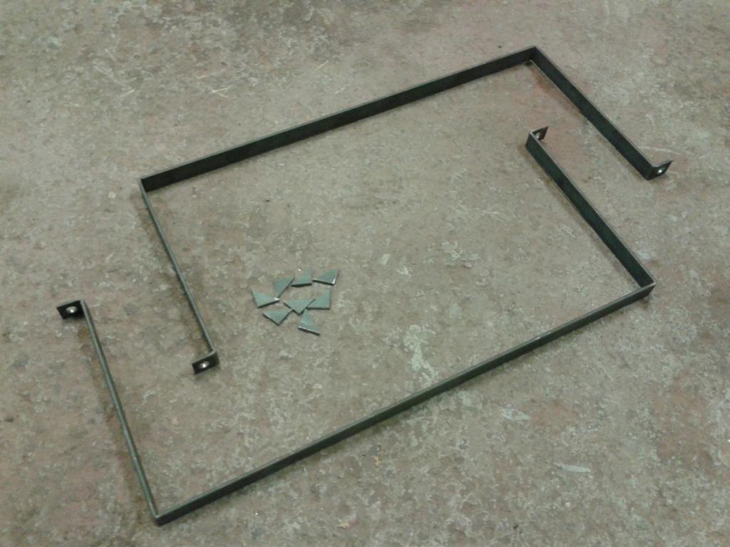
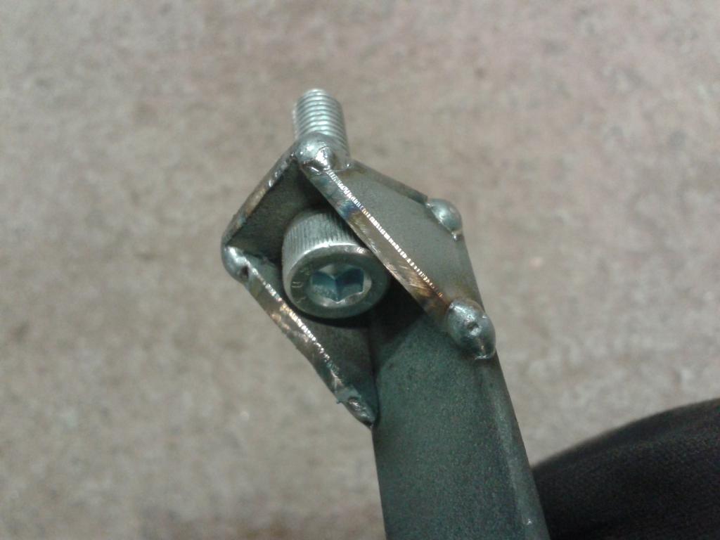
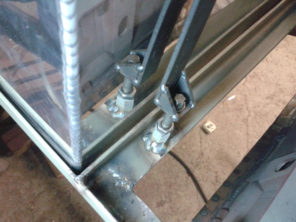
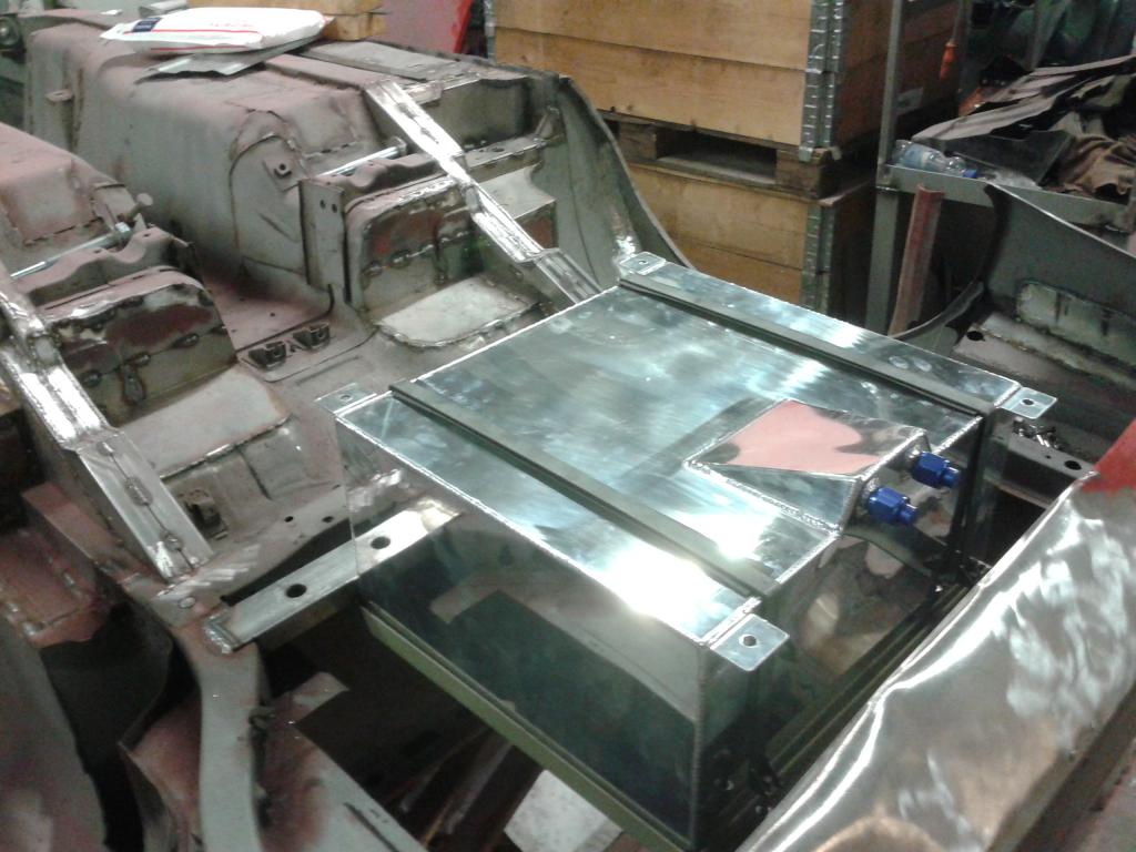
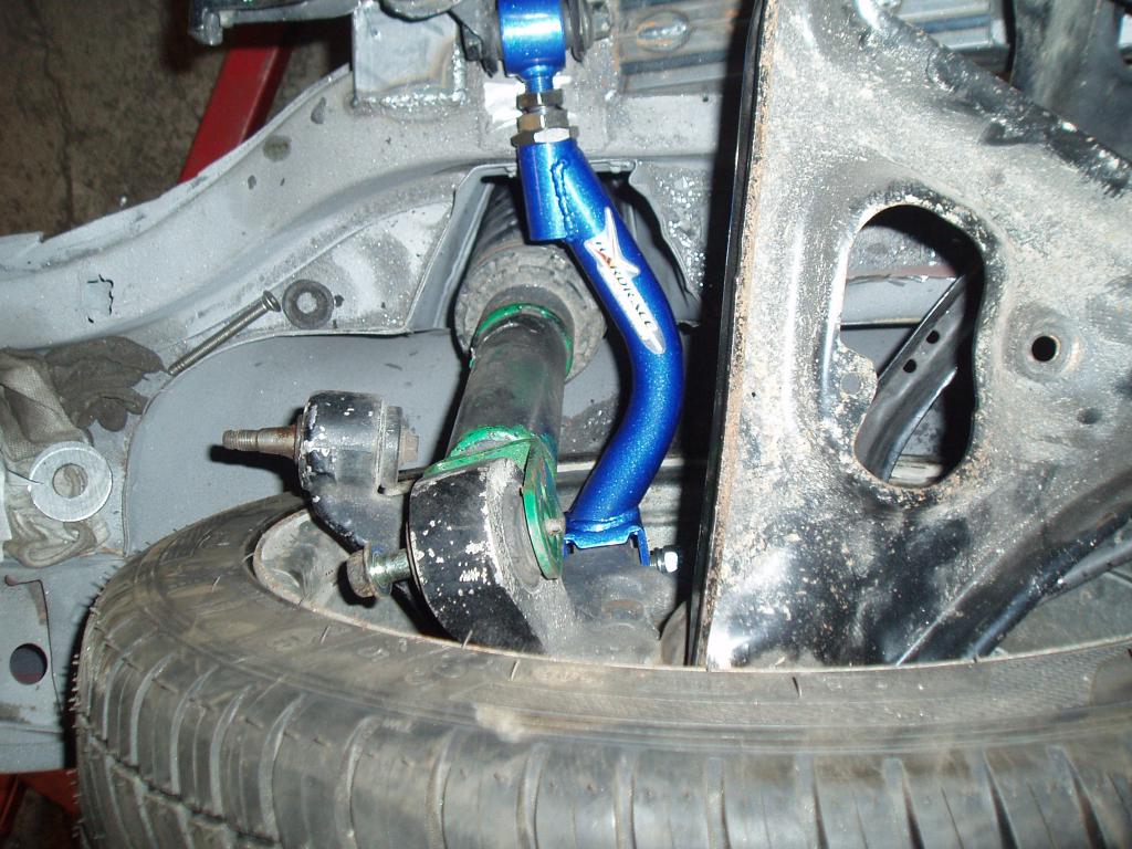
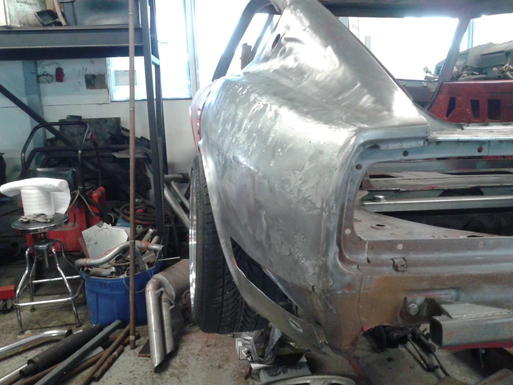
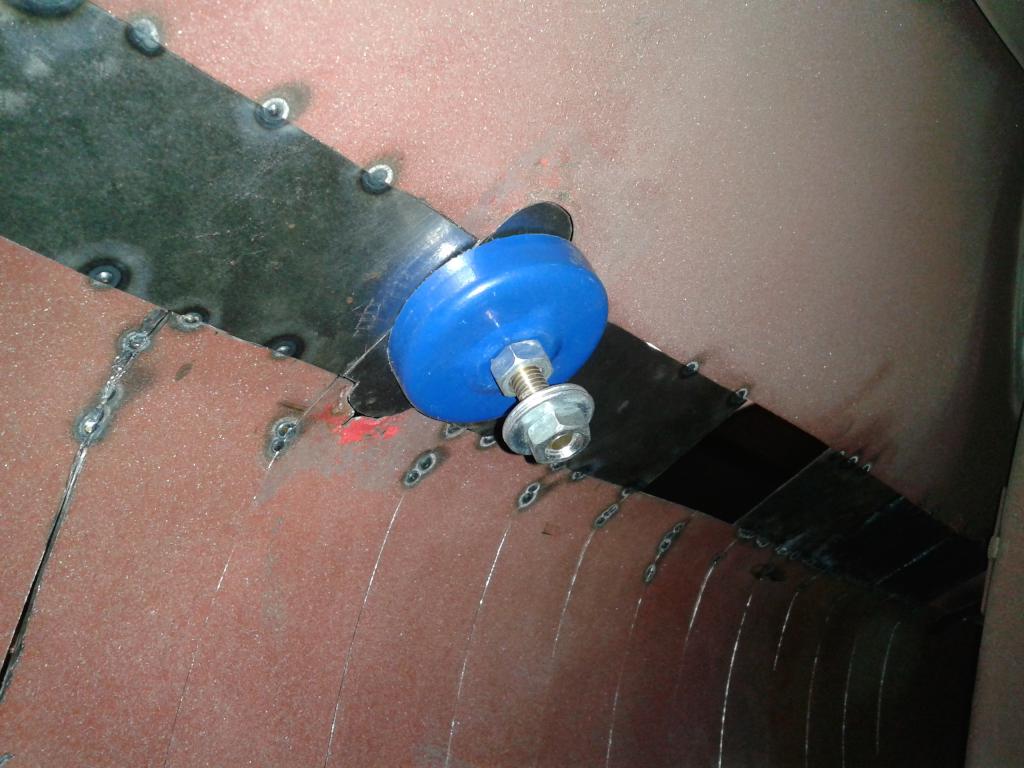
After the rear axle mod I put some serious effort on the widening of the body. As already mentioned, the progress of that work can be found here: http://forums.hybrid...y-widened-240z/ With the sheet metal work related to the body widening pretty much done and the car still conveniently hanging on the rotisserie upside down, I figured it was time to fabricate the fuel cell mounts. The fuel cell is an aluminum 15 Gallon unit. The cell can be installed from underneath the car and the main idea was to preserve the stock floor level of the trunk, but obviously without the spare tire well. In this kind of installation the cell sits quite low, but the GTR subframe is still more near the ground and guards the cell if something were to hit the car from underneath. I still need to get some suitable rubber inserts between the straps. I already found suitable rubber webbings to go between the cell and the metal frame. The straps are bolted on to M8 distance nuts which are welded to the cell frame. In the front, the straps are firmly torqued against the frame, but in the rear there is a gap between the strap and the frame purposely left to enable tightening to desired tension of the straps. Once set to the desired tension, the bolts are locked in their place with a nut. Some might be thinking, why go through all that trouble, but I made the installation like this, because I didn't want any bolt heads sticking on my rear compartment floor. I thought there was plenty of room for the fuel cell, but the reality is that there is no extra space. At first I almost forgot the hicas system of the GTR rear axle, but luckily remembered to check the clearance. The hicas will be substituted with conventional control arms, but if the hydraulic cylinder fits, there will be no trouble installing a hicas delete. Here are some pics of the fabrication process:
-
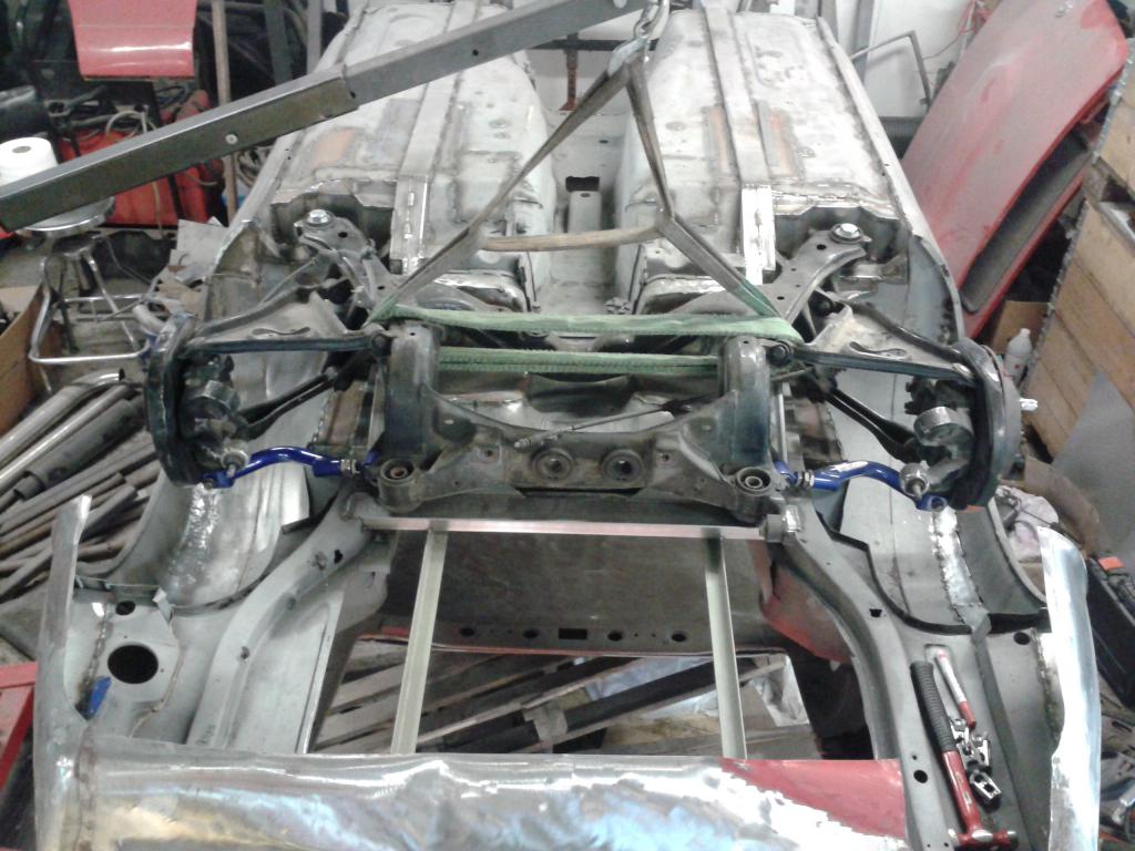
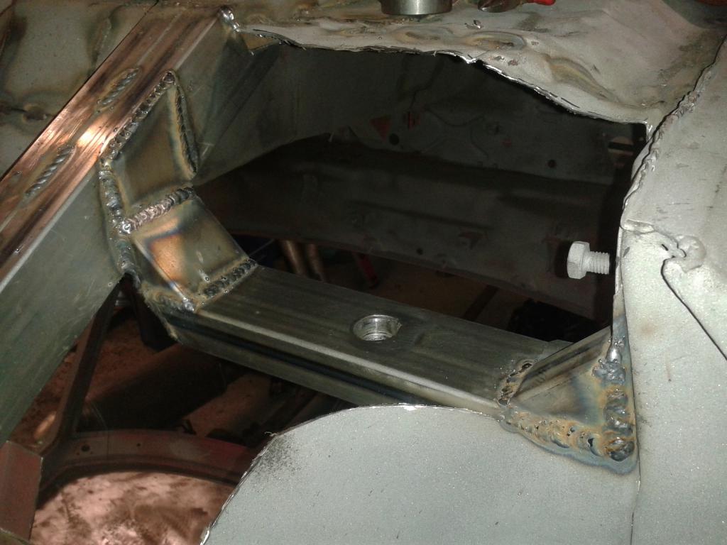
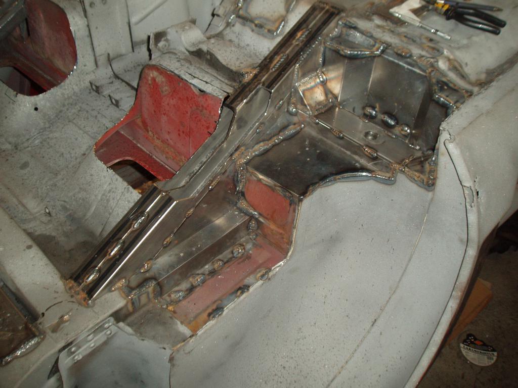
I started my work with the Z by customizing the rear axle area to accept the GTR-32 subframe. The idea was to install the subframe in the height that would preserve the original control arm alingment and geometry. Basically this meant some serious cutting of the original sheet metal body and fabricating totally new mounting spots. The attached pictures are from various stages of the work. The modification is pretty much done now, requiring only some finishing touches here and there.
-
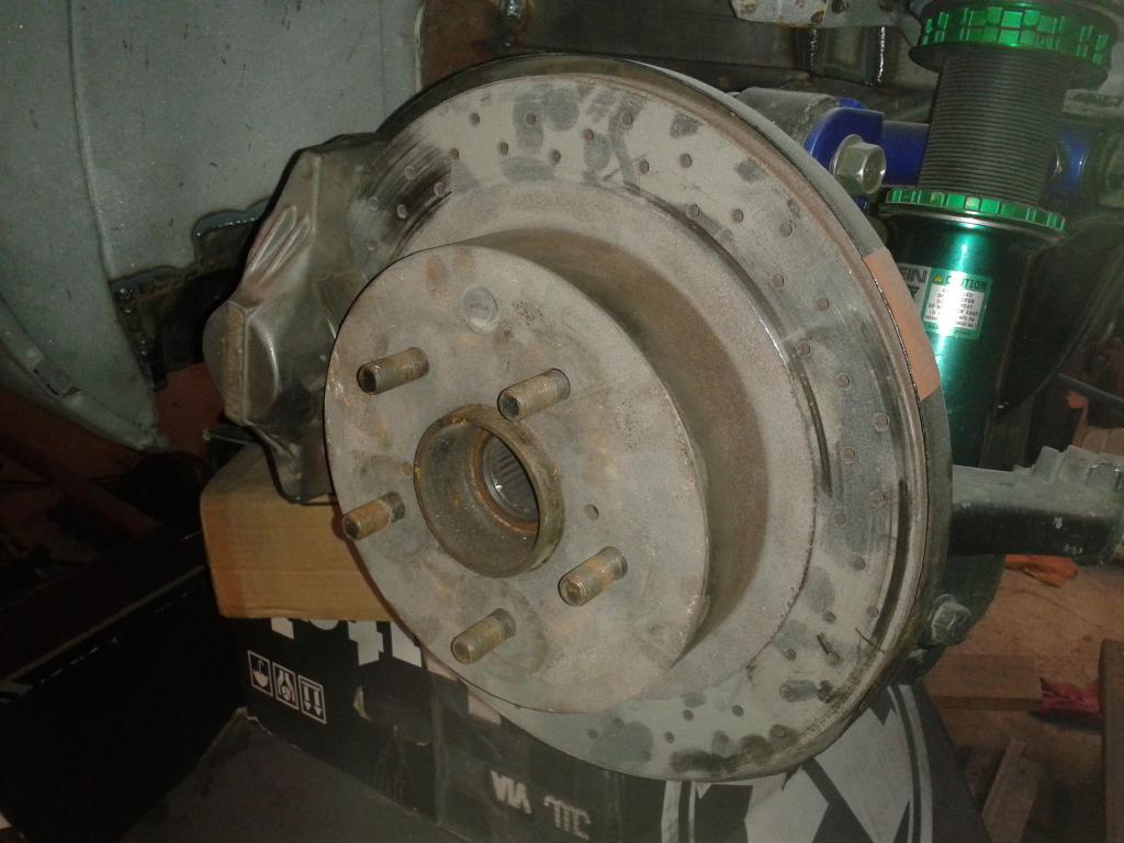
My car is a -72 240Z which I bought as a project that the previous owner had started several years ago. When I first got the car it was on bare metal. I will first try to list all of the relevant progress that the previous owner had already done: - complete tear down of the car - Stripping all the surfaces on bare metal, partially by sand blasting and the rest by other more gentle methods - Rost damage repair here and there - Reinforcement welding of the body seams - Replacement of the original longitudinal sheet metal beams with profile - Mitsubishi EVO Tein adjustable coilovers to the front - Front camber plates - Arizona Z-car type lower control arms machined from steel - Spare tire well removed - Fuel fill hatch removed With all this work already done it was a good starting point for me. Here is a list of all the work I have planned for the car: - GTR-32 rear subframe assembly - Mitsubishi EVO Tein adjustable coilover suspension to the rear - 5x114.3 front hubs as the rears will be converted to 5x114.3 with the subframe implementation - GTR-32 brakes on all corners - bolt-on partial roll cage - 15 Gallon aluminum fuel cell installation - Body widening with a totally different approach - BMW M60/M62 V8 hybrid engine which will be supercharged - Magnuson M90 supercharger - Lighter flywheel - Getrag 420G 6-speed manual transmission from an E39 BMW M5 - MS3 fully sequential engine management - BMW E46 M-Sport seats (brown leather) - Restoration of the interior As I have already had the car for awhile, some of the action points are already done. For example the GTR-32 rear axle already sits at it's place. I'll be posting some pics of the work done on that shortly. Some of you have probably seen the body widening progress which I've documented over at the "Body kits and paint" section. Here is a link to the thread: http://forums.hybridz.org/topic/117948-my-widened-240z/ Here is a picture of the car before it was dismantled and in the status as it first came to me:
-
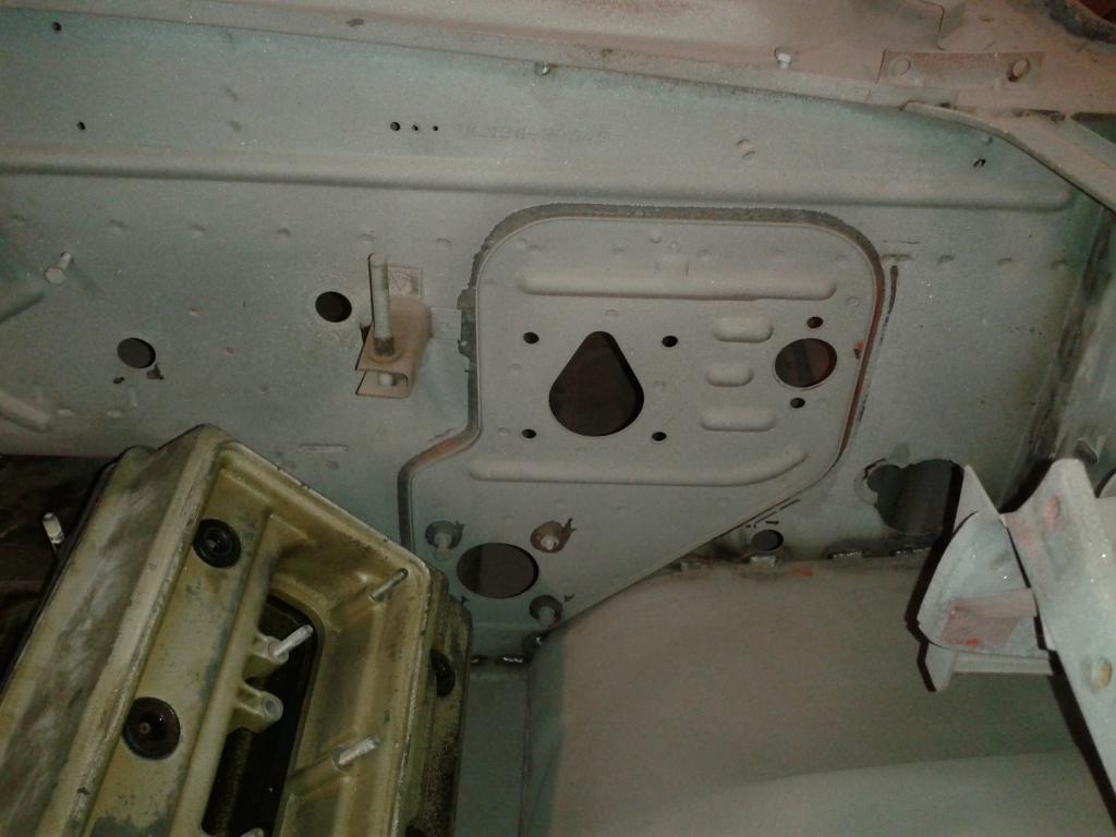
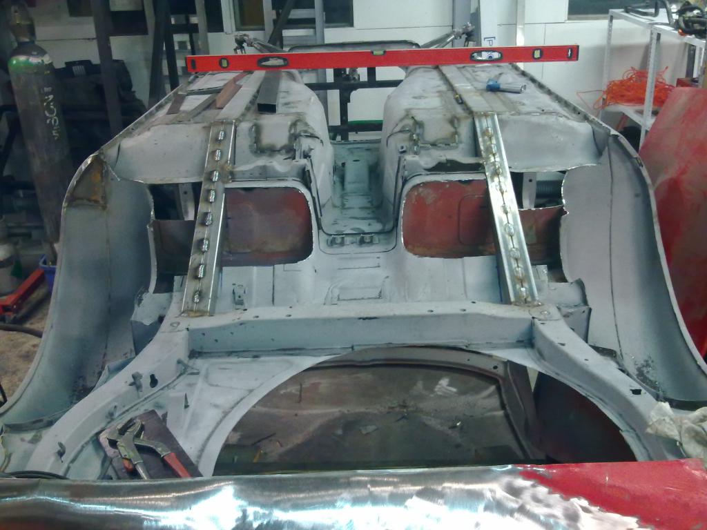
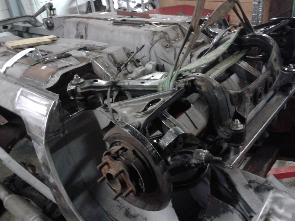
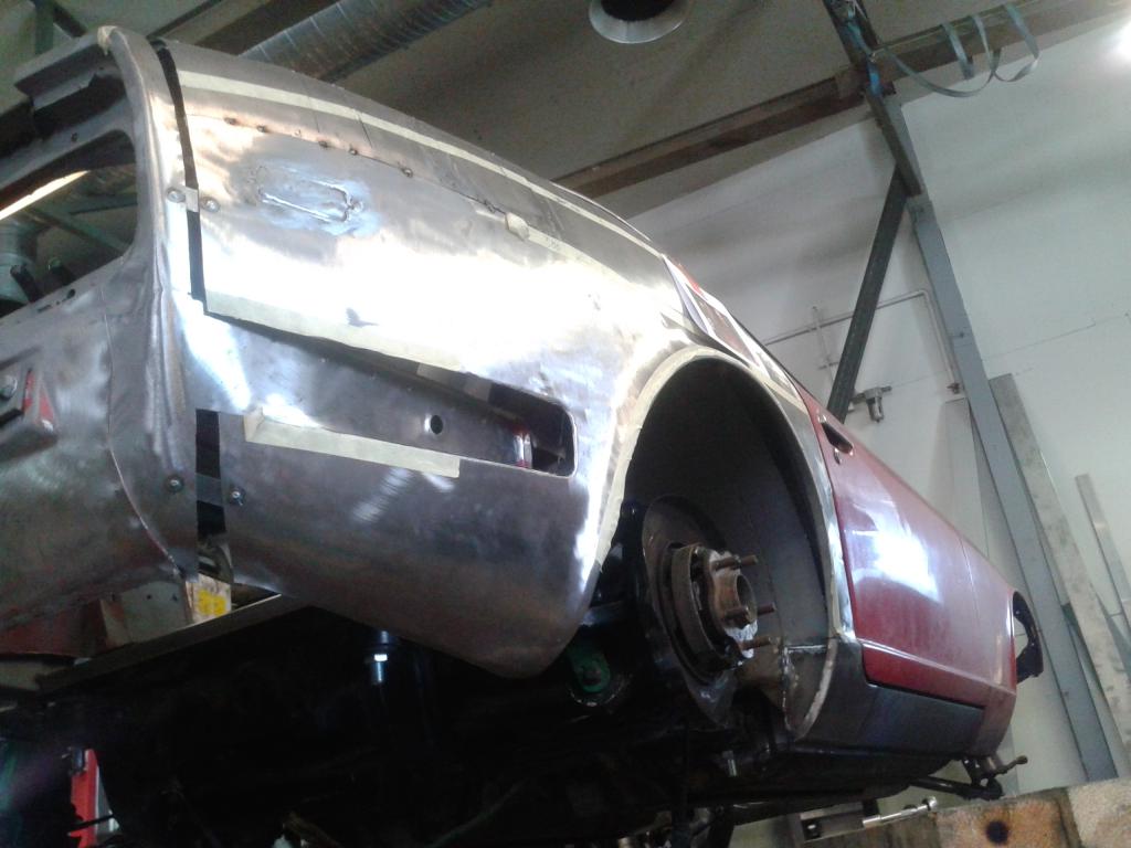
The progress has been quite slow lately. After getting all the sheet metal work of the visible surfaces done I patched up the gaps in the inner fenders. At the moment I am working on the fuel cell fixture and will post some pictures of the that when it is ready. In the mean time, here are some pictures of how the inner fenders look and how the GTR sub frame sits:
-
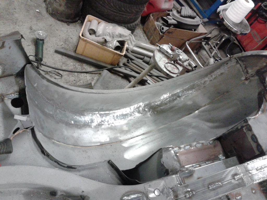
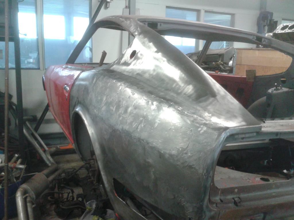
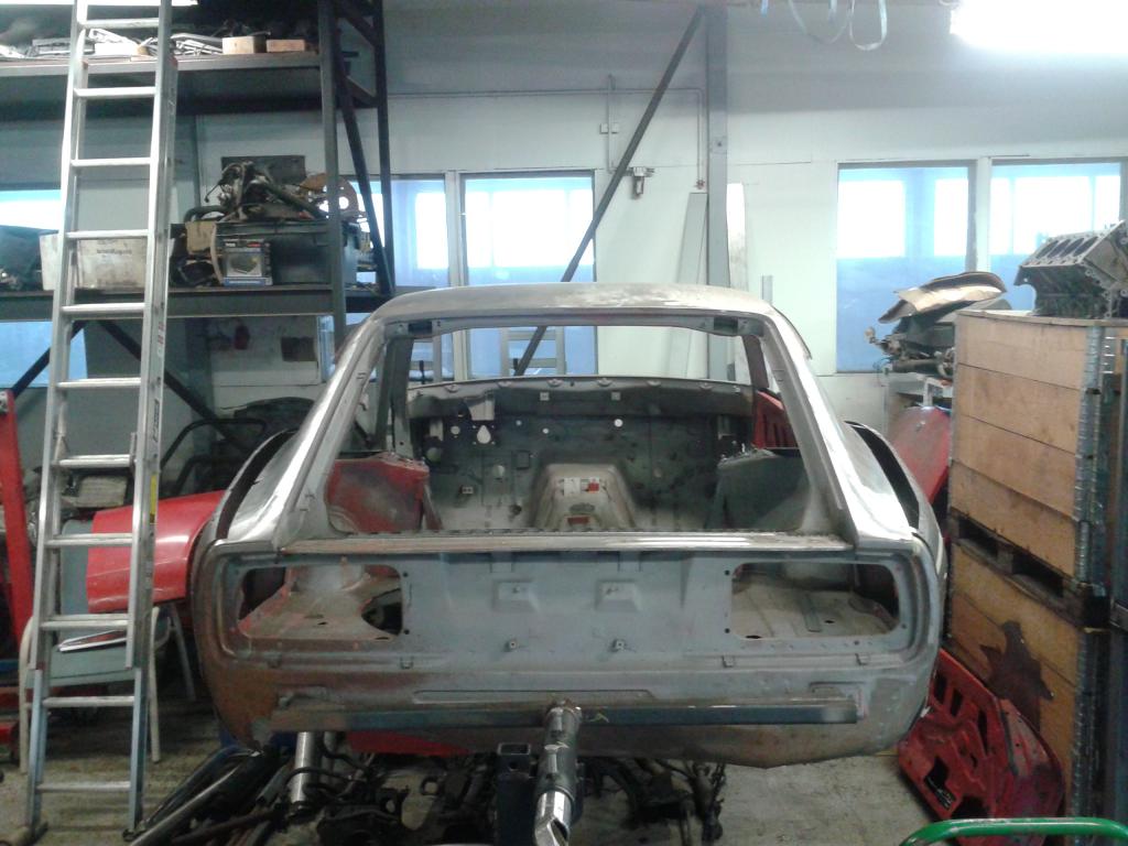
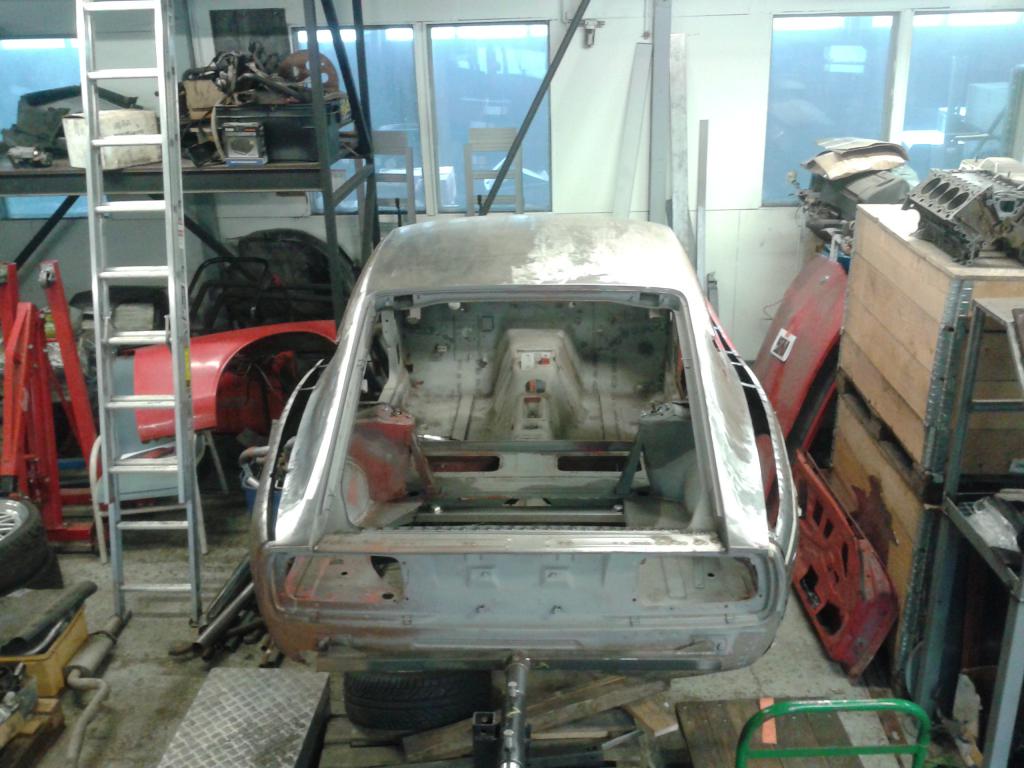
Me too! The amount of work this modification requires is damn near overwhelming. I wish I had more spare time to commit to this built... I decided to ditch the rear bumper and sheet metaled the holes. I guess you could say I reached a certain miles stone now, since all the sheet metal work of the visible surface just got finished. All of it related to the body widening anyways. I still need to figure out what to do with the bumper fixing points on the rear and seal up the nasty exhaust pipe opening. Paint will still have to wait, though. At least the fuel cell mounts and the trunk floor will need to be fabricated along with the seat mounts before I coat her with some epoxy primer. Here are some pics of the progress:
-
Yes, I am aware of this and propably will go the custom three piece road someday. There is a good amount of back space, the GTR axle just don't allow for much lip on the rim or an ET typical for an RWD. The back space might allow for a 10" wide rim with a suitable offset.
-
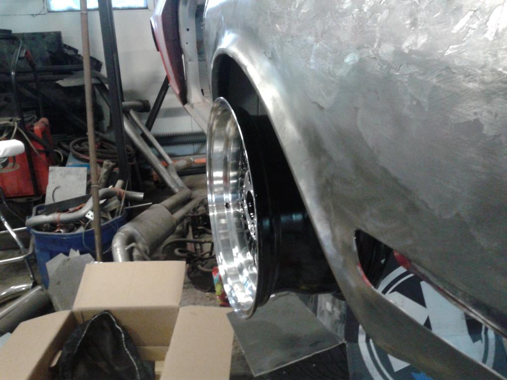
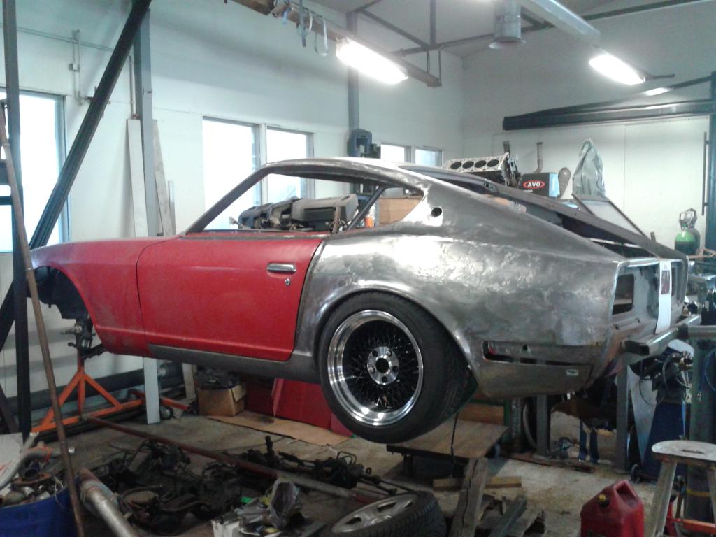
I ran into trouble fitting the 9" wide wheels with the brake calibers in place. Turns out the GTR double piston calibers come too much out and hit the rim already without any tweaking of the offset. With all the trouble with the fitment of these rims, I decided to try out the 8" wide rims, that were meant for the front. They clear the the caliber and the alignment with the fender is perfect. I can probably get away with some rolling of the inner lip. This will do for now, although I would have really wanted wider rims. I guess I'll just rethink the 3-piece rims someday.
-
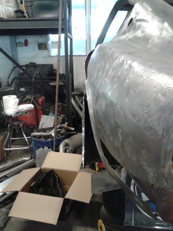
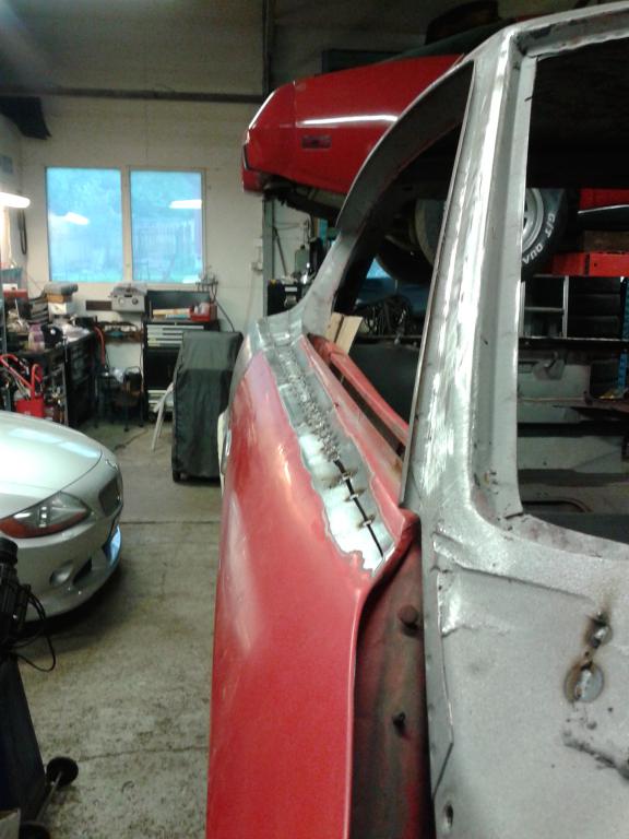
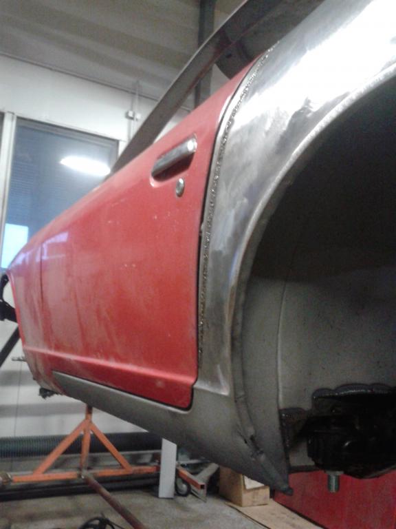
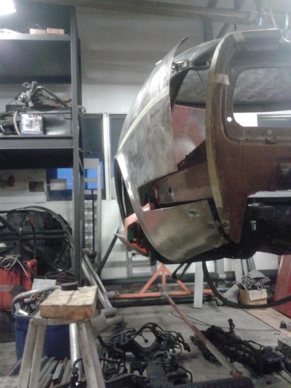
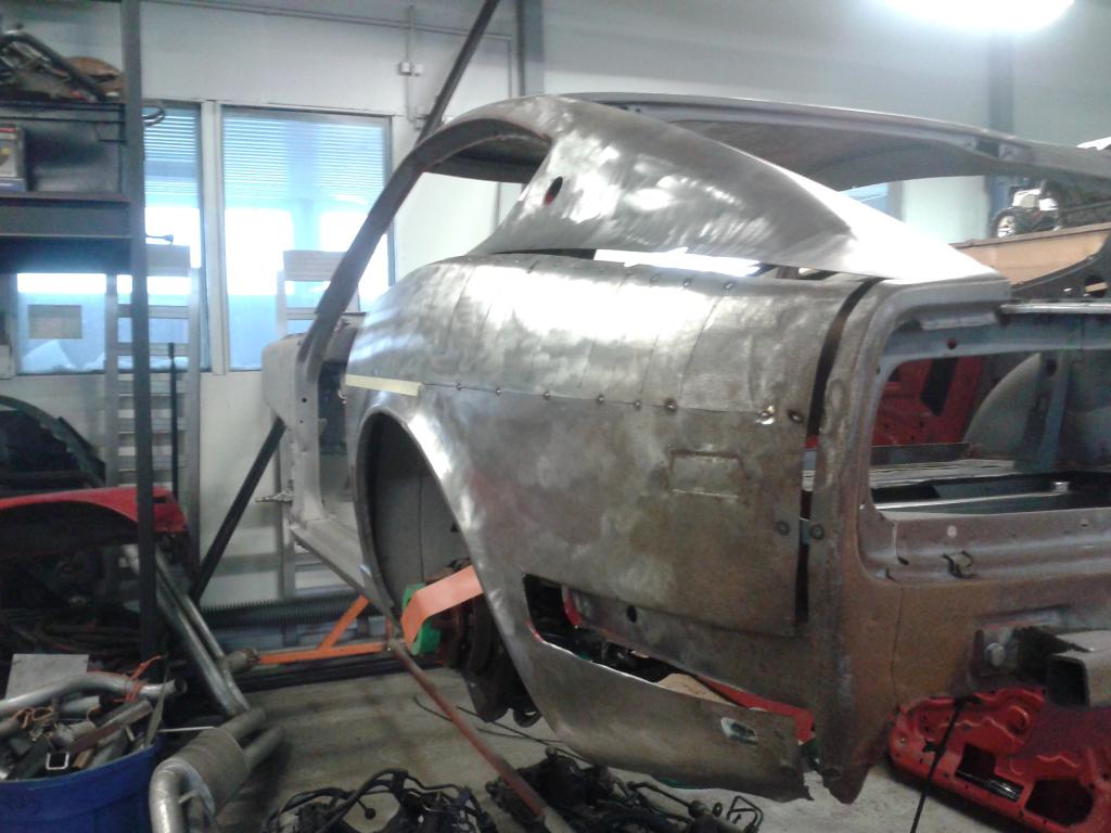
The OE fenders might get under the knife if rolling of the inner lip along with some camber does not do it. What kind of camber angles are people running on these things? I have the GTR-32 rear axle equipped with adjustable upper camber arms so I can play with the angle quite freely. In the mean time. Here is some pictures of the tack welded passenger side and door fitment. I was also quite eager to check the symmetry, so I climbed up a ladder to get a "new angle". The money shot shows the new curves quite nicely. Seems to be symmetric.
-
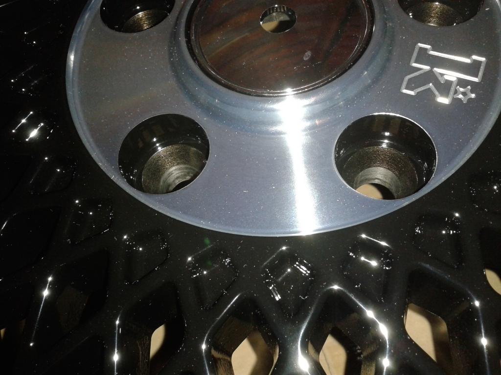
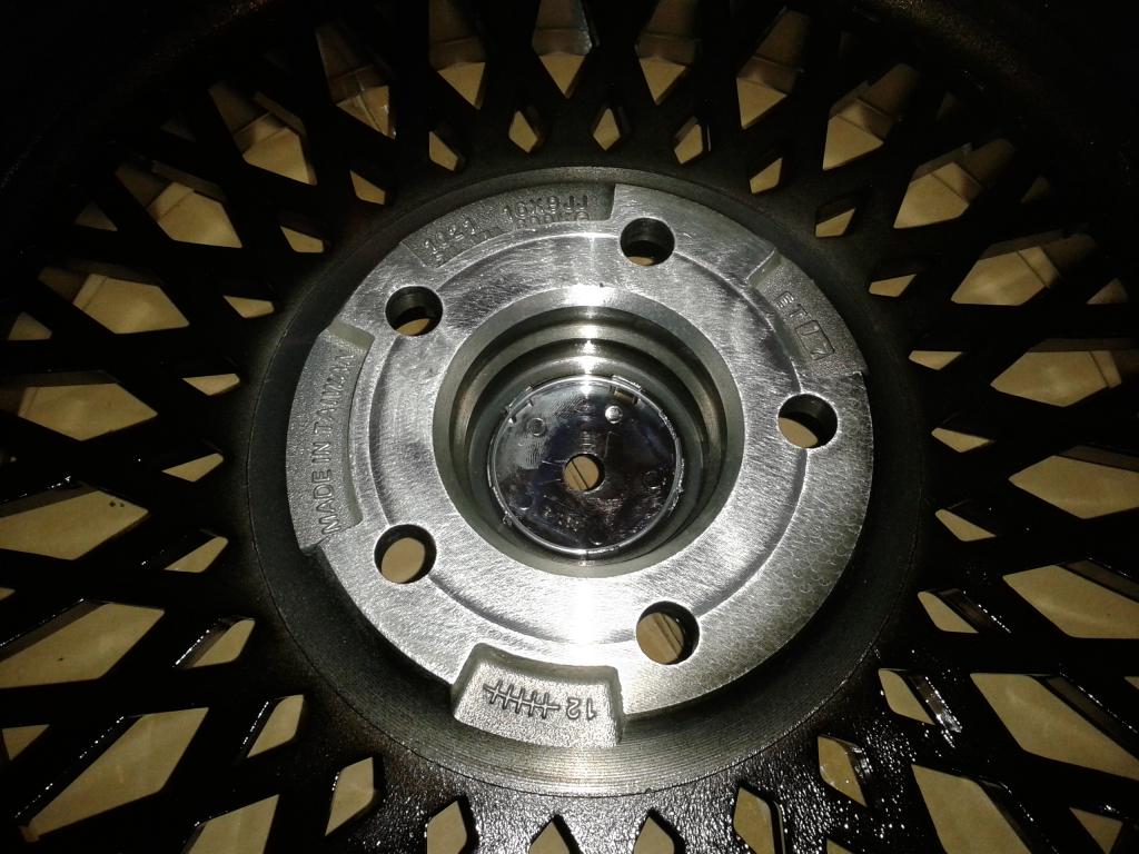
The problem in the fitment is due to the GTR32 rear axle which is considerably wider than the 240Z stock rear axle. With 9" wide 0 offset rim the situation would be even worse since my rim is ET17. After all this trouble, the modification of the stock flare will be a walk in the park. My main concern is that I'll ruin the looks, but if I do it as shown in the linked Youtube video, it should look just right. As I mentioned, there is also the possibility to machine the rim to increase the ET. In the first attached picture, you can see the cone shape in the bottom of the bolt hole where the bolt is to be seated. After the cone there is 12.5mm (1/2 inch) of material thickness. The back side of the rim can be seen in the second picture. The markings are 10mm lower than the mounting surface. Taking 8mm off from that surface would bring it to ET25 and there would still be 4.5mm of material (actually a bit more due to the cone shape) to fix the rim in place. Could anyone measure their rim to see how much material thickness there is as a reference?
-
I did not check the clearance to the strut, but you are probably right. The problem is I really like these rims and this is the most positive ET that they (Klutch SL1) come. There will definitely not be any fiberglass flare coming on top of this. I am talking about an approach such as depicted in this Eastwood video: https://www.youtube.com/watch?v=4ksUcM76nrc With some additional fender rolling applied to the inner lip, I do not think the subtle look will be ruined.
-
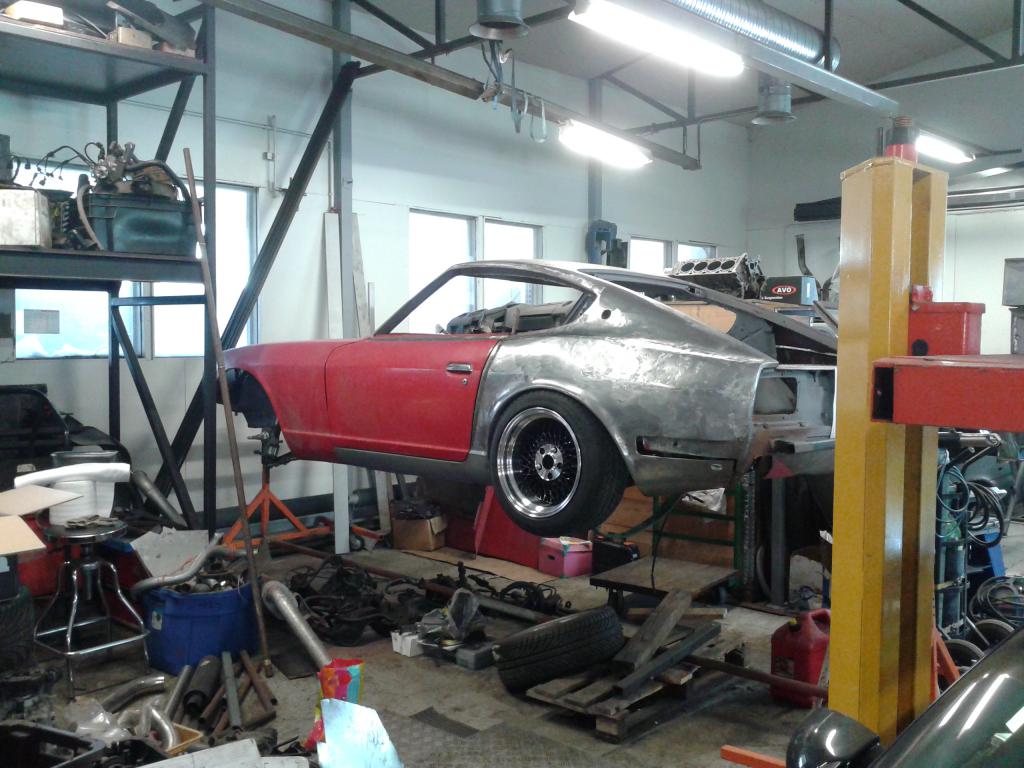
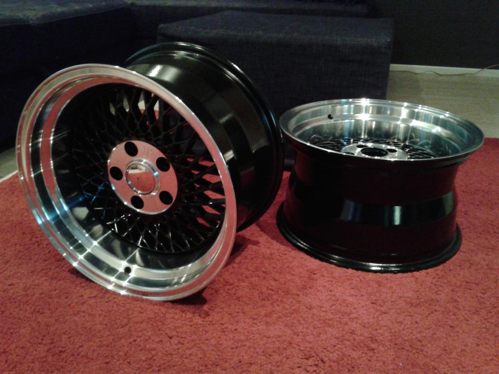
After a long wait, I finally received my rims. The wheel spec is 16x9 ET17 with 225/45 tire. I adjusted the camber to zero degrees to check the clearance (or lack there of) to the fender. The fitment is tight, which did not come as a surprise. The options now are: Machine the rim to get more positive ET or fabricate a wider fender flare out of the OEM fender. Since there is no guarantee of endurance of the rim if machined and the amount to be machined would be substantial, I am leaning towards fabricating a wider fender flare and rolling the inner fender lip to get clearance fir the wheel. The down side of this approach is the fact that the body is already widened 2" on each side which happens to be the maximum allowed amount here in Finland. The outcome is quite subtle though. So the inspection officer probably wouldn't know what hit him. ...And the current status:
-
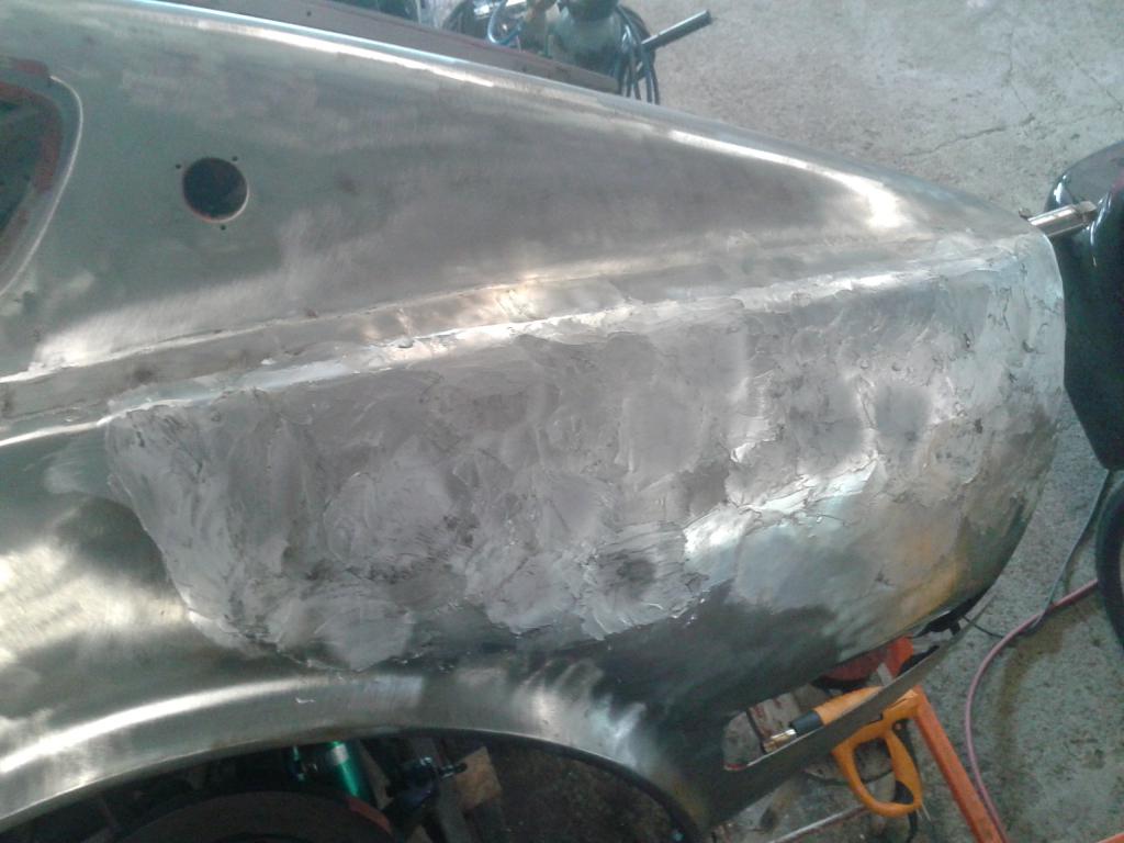
I am leaning towards deleting the bumper, but we'll see. In the meantime I've been doing some body soldering which I've never done before. As opposed to my expectations, I did not have much difficulty controlling the melted solder. The most difficult part for me was to apply the correct amount of solder to the right places, the result being that after planing some spots were left on a pit. These will be flattened with some body filler since the thickness required will be less than one millimeter. Here is some pictures of the body soldering:
-
Thanks for the ideas. Modification of the bumper might end up being a pricey solution because I would like to maintain a chrome finish. Running the exhaust out of these holes would be something different. I guess I'll leave it for now and see how the bumper fits when I take the car down. Next I will be practicing on body soldering. Let's see if it goes well enough so I dare to share some pics of the result.
-
What do you guys think of the situation with the rear bumper? As it stands, my options are wide open. My initial idea was to embed the bumper into the widened rear quarter, but I am wondering if it is going to go below the surface of the panel. Might look a bit odd if this were to happen. The obvious way to go about this is to just sheet metal the void and ditch the rear bumper all together. My friend suggested I put a metal net on the front of the void and sheet metal the sides to create a kind of ducting for cooling the brakes. I am not sure how effective this approach would be in terms of cooling, but would it look good? If anybody knows of any car with a similar solution, I would appreciate the info.
-
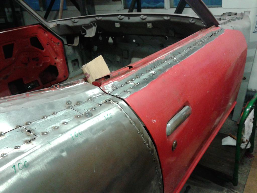
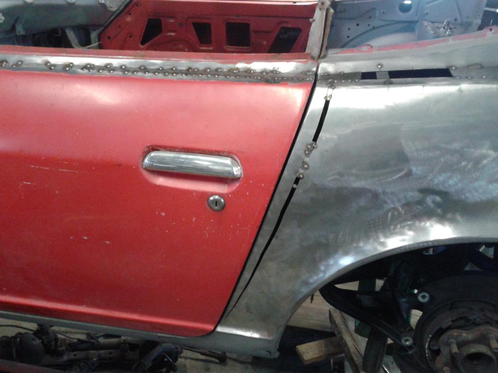
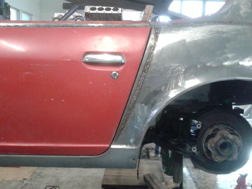
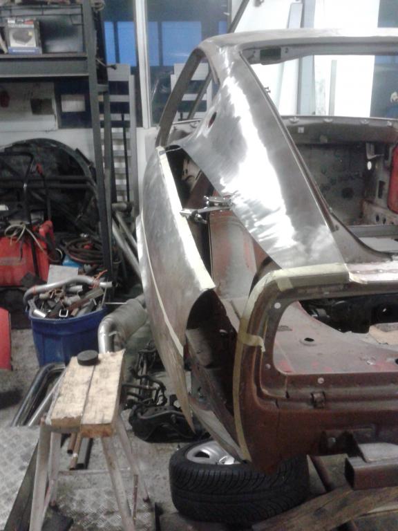
When the quarter panel was pulled out and bend on a smaller radius, the gap between the door and the panel was widened from the top. I made a new vertical cut to the panel and restored the uniform gap as can be seen from the first photo. The modifications and fitment of the door can be seen from the other photos.
-
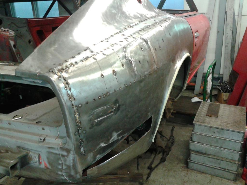
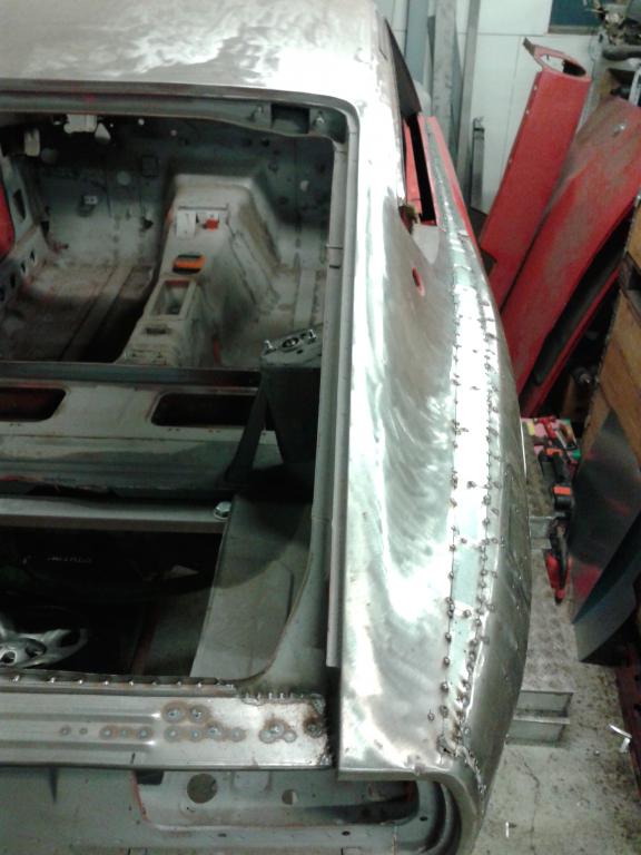
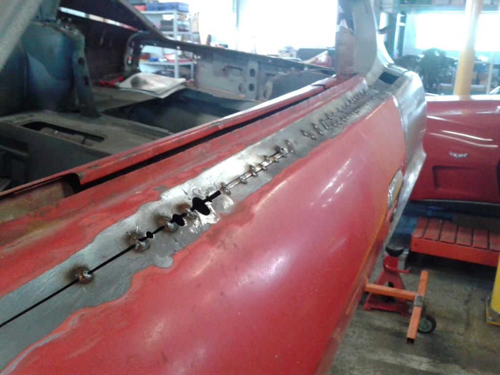
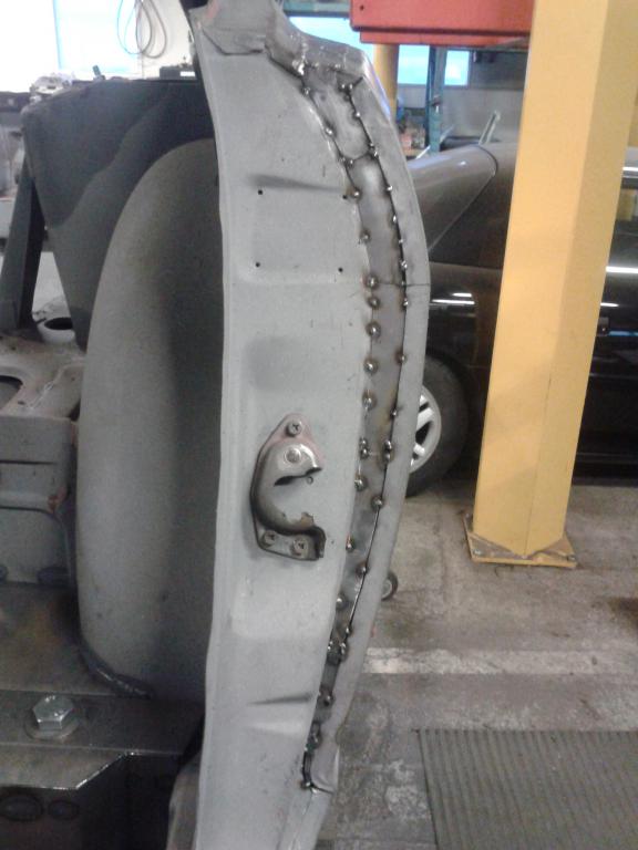
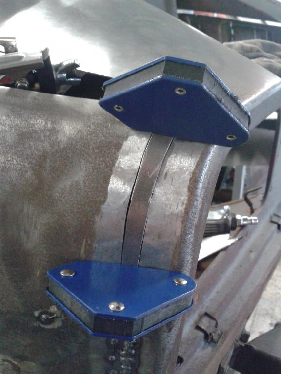
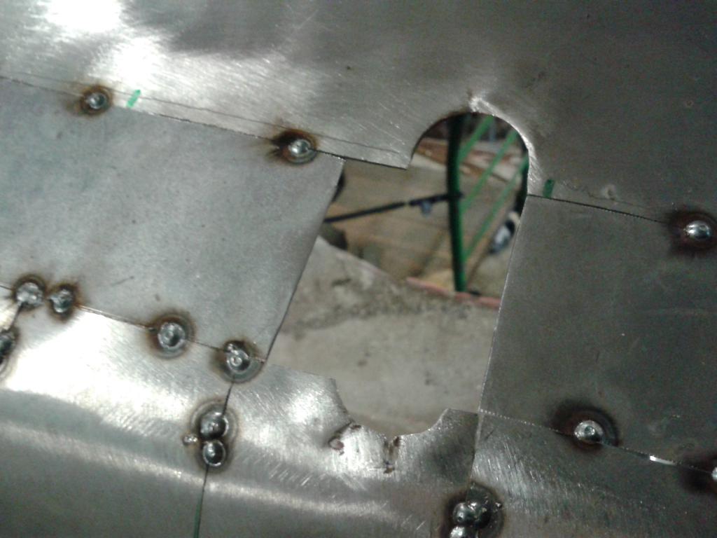
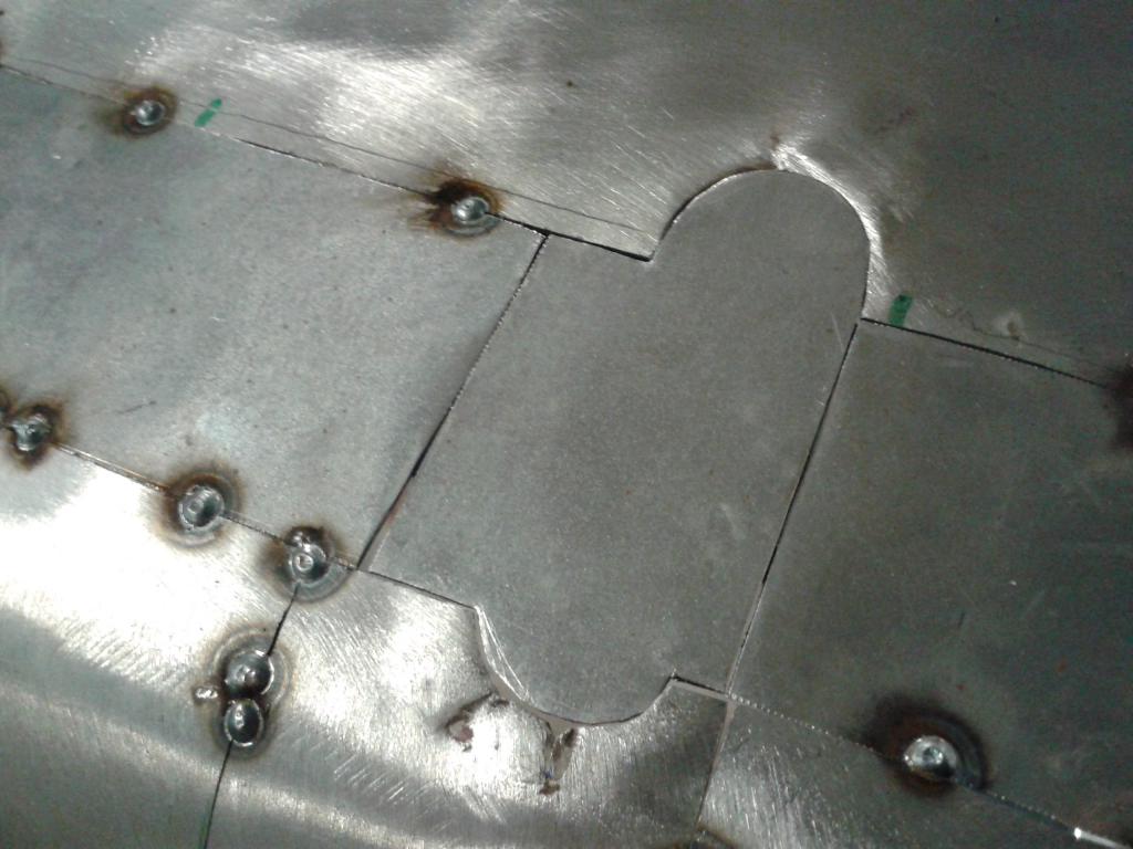
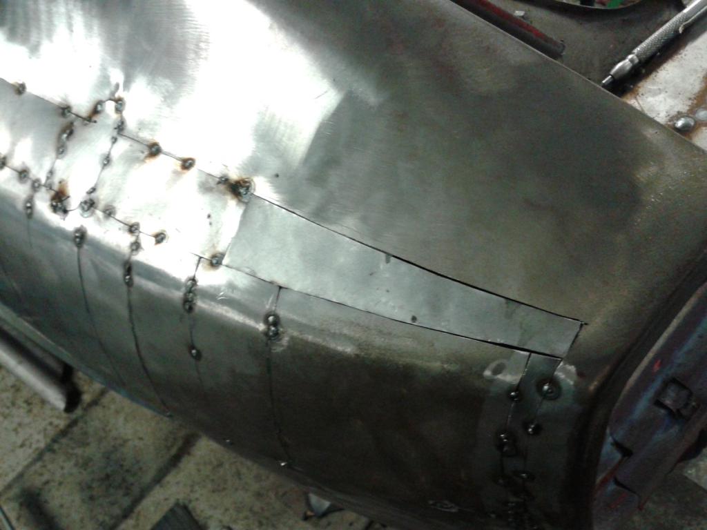
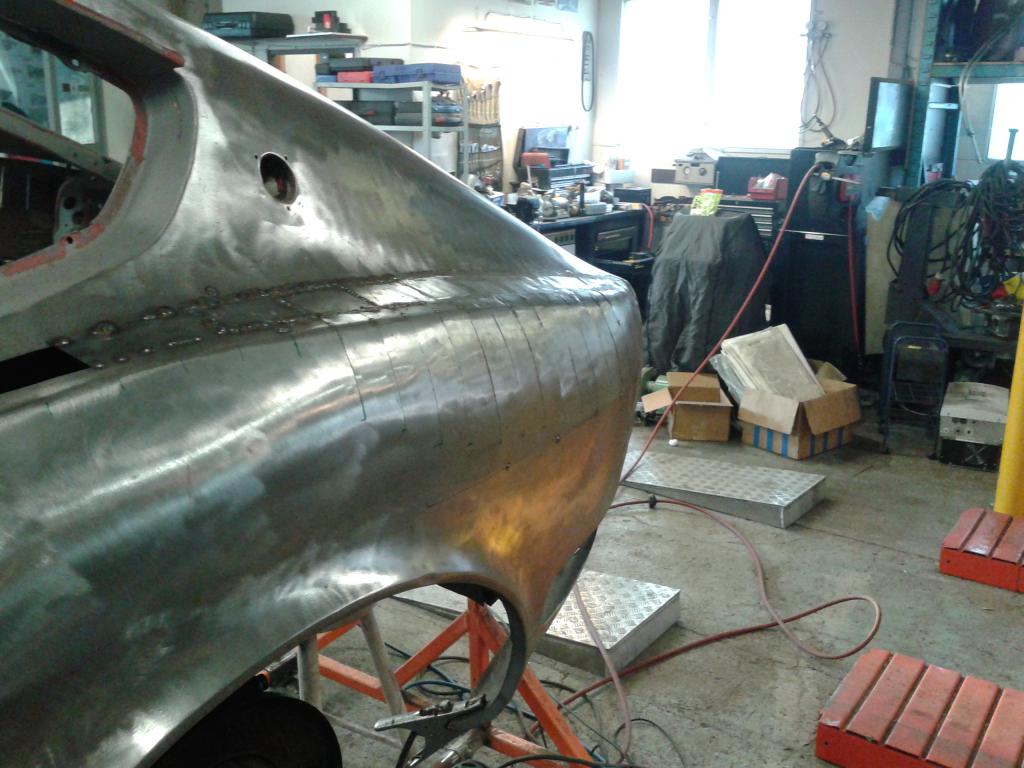
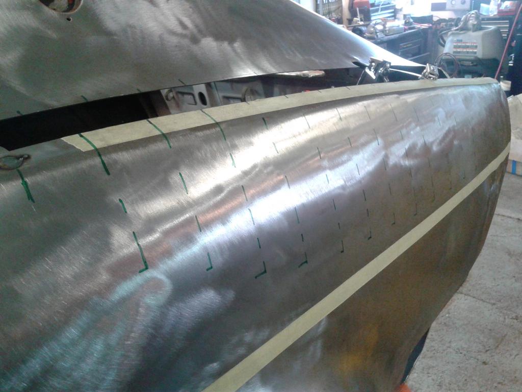
With everything looking as if there is a possibility to make this all work, I went on to sheet metal the created gaps between original body sections. All sheet metal parts are cut to the shape of the gap and fitted with butt joints. I am not really sure if that is the correct term for this but what I am trying to describe is that I do not put metal on metal but new metal comes parallel to the original metal. The shaped sheet metal pieces are first tack welded to assure correct fitment and afterwards all the seams are fully welded Photos are pretty self explanatory and I try to document my progress as I work so here is some pictures of the sheet metal work on the driver side rear quarter panel and finally some surface area with the welding seams grind down and ready for some body solder.
-
The cut made to the door right on the top bodyline can be seen from one of the pictures I posted. The front end of the door stays at the original position while the rear is stretched out. The door was widened a little shy from 1.5 inches from the rear top end. The bottom of the door is kept in the stock position as well. After the main body shape was found on the passenger side and I finished tack welding it so it sticks together, I decided to modify the other side. This was pretty straight forward since I made coordinates of my cuts. I just replicated the coordinates to the driver side and took out my jigsaw. Here are some pics of my progress on the driver side. The sides are as symmetric as can be at this point, but the welded fuel tank lid on the passenger side caused some discrepancy as I cut open the structure. Not a major issue though. Nothing a gentle hammering and a little body tinning wouldn't sort out.