

Boben
-
Posts
401 -
Joined
-
Last visited
Content Type
Profiles
Forums
Blogs
Events
Gallery
Downloads
Store
Posts posted by Boben
-
-
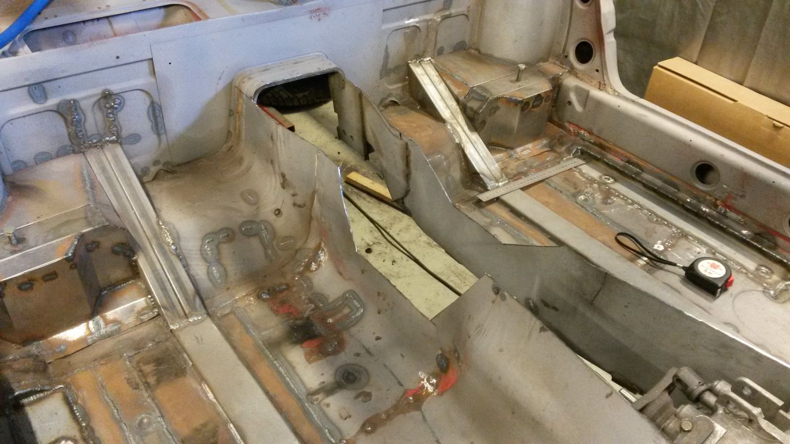
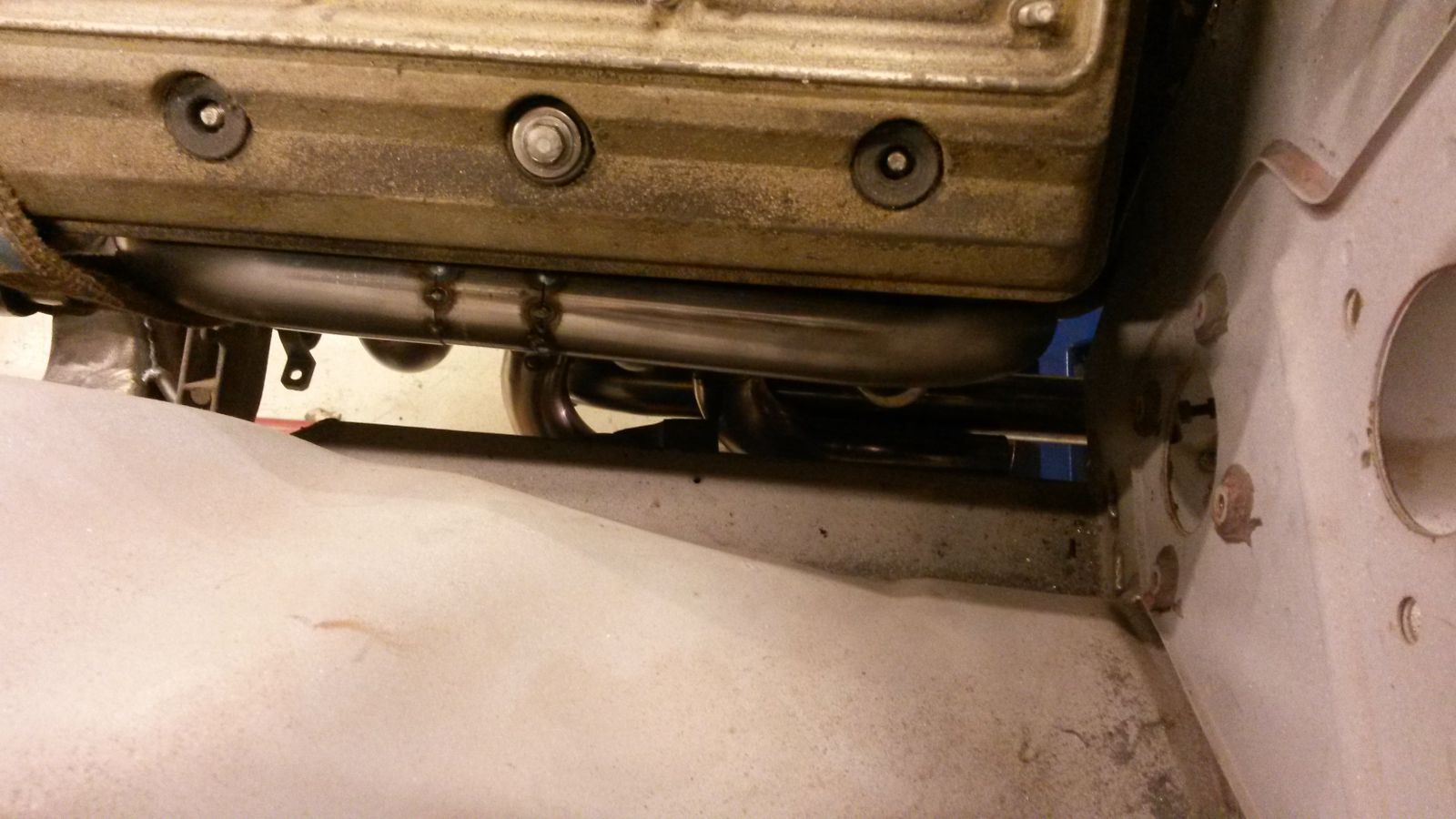
I have been contemplating the rising of the center tunnel almost from the get go. After installing the exhaust manifolds I was faced with the fact that the steering shaft just was not going to fit. I had decided not to include the rubber joint of the shaft to the model and sure enough one of the primaries hit that. Also there was quite little clearance from the exhaust to the longitudinals. I knew the engine was sitting low with the oil pan bottom surface level hanging below the bottom of the x-member. With so many problems to be solved by lifting the engine and transmission, I decided to cut out the center tunnel and see if I was able to lift them. I raised the tunnel 45mm from the front and a little less from the rear. The engine and trans was lifted 35mm. Clearance between the modified steering axle, motor mount and the exhaust basically defined the new engine position. The tunnel height was defined by clearance to the bell housing, clearance between the drive shaft and shifter mechanism and the parking brake mechanism.

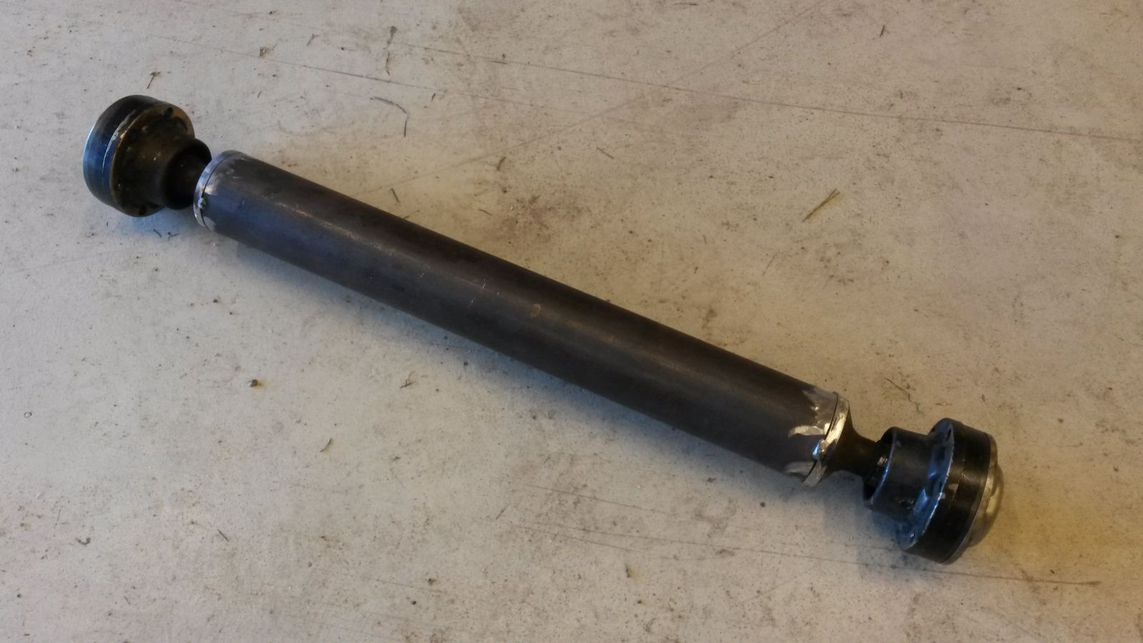
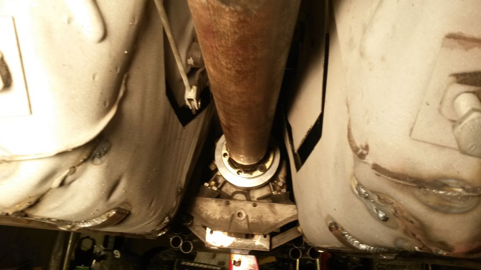
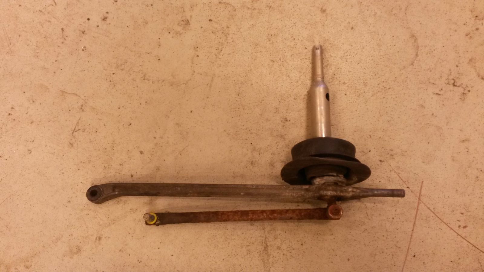
I received the billet adapter for my drive shaft from the machining shop. The transmission side was done according to measurements from the original rubber joint.
The drive shaft side was done according to the measurements taken from the CV-joint sealing cap.
And here is the drive shaft. At this point only tack welded for initial fitment.
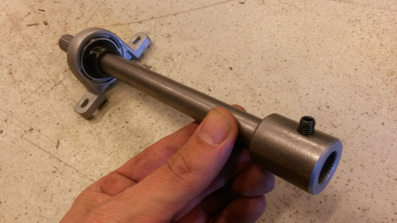
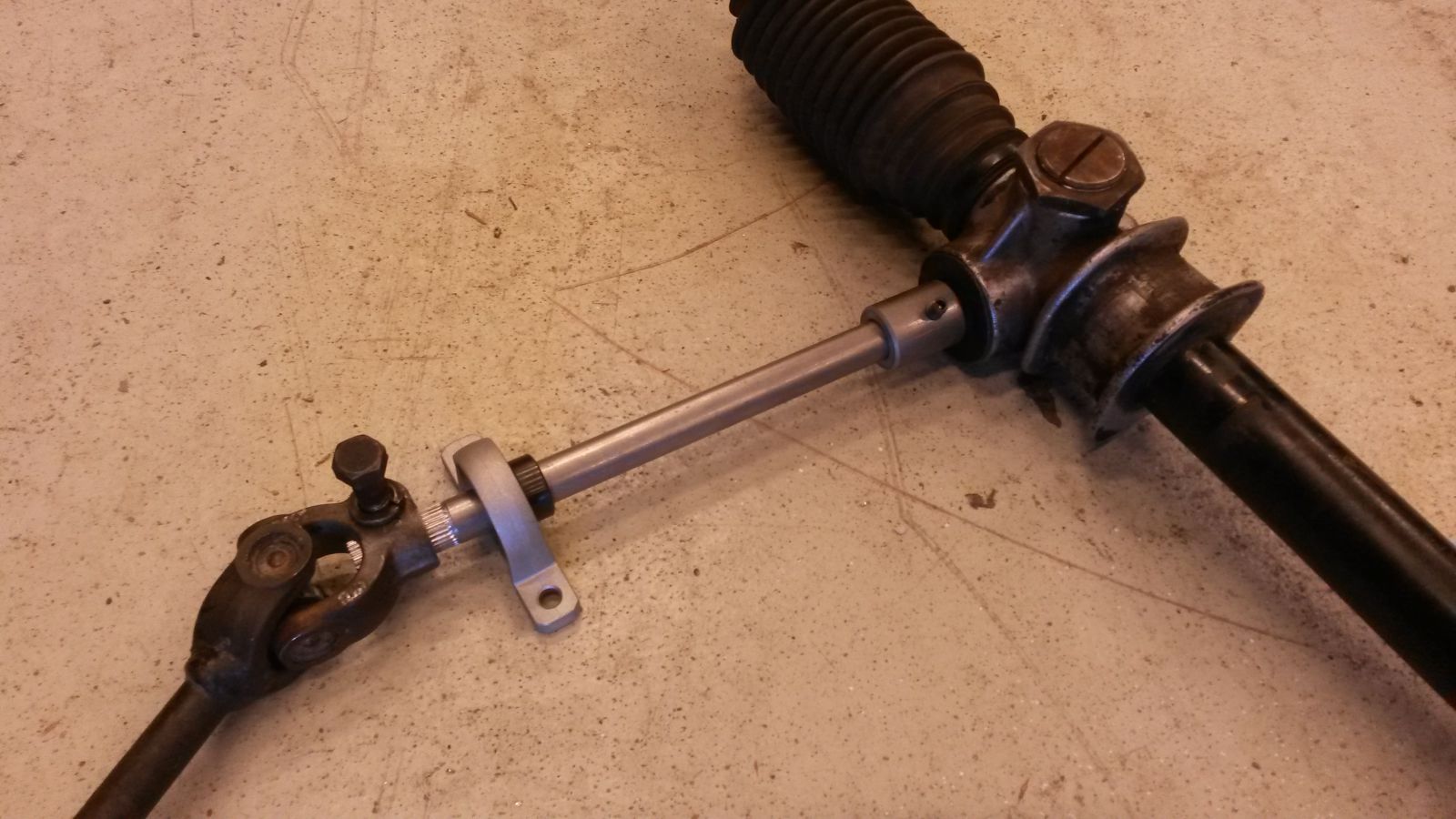
Here is the extension shaft which connects to the rack.
This is the new height position of the tunnel.
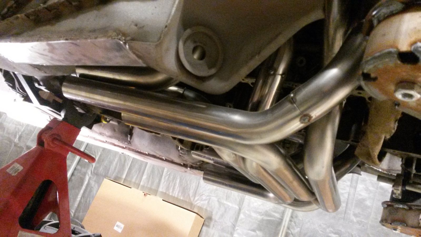
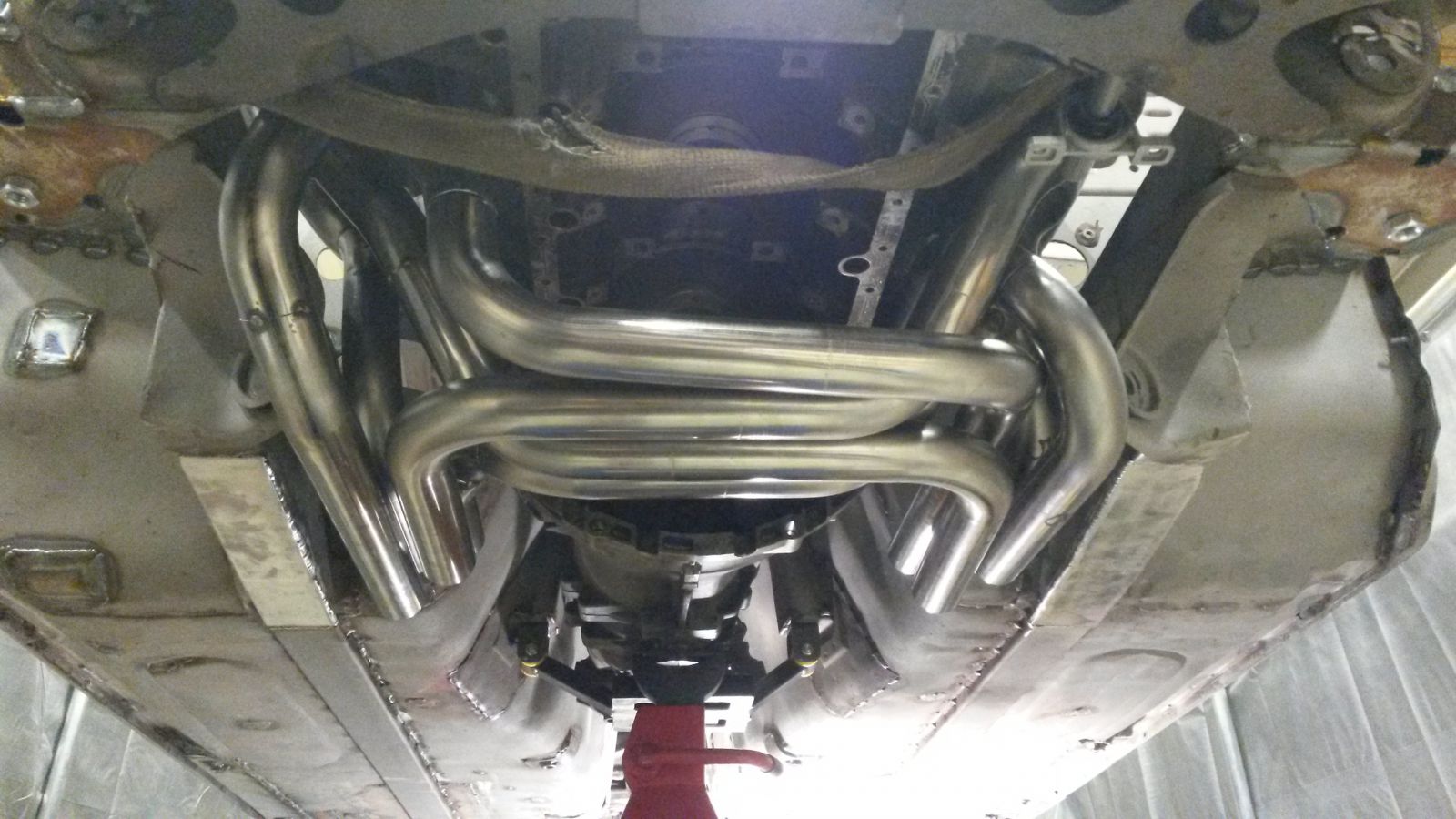
Some pictures of the exhaust manifolds in place.
Here is the extension to the steering rack axle.
-
Amazing attention to detail. Love the body work and the effort to maintain such a civilized car!
Thanks, the progress is slow and I do find myself fiddling around with the little details time and time again.
-
I meant 30p4s as in first making four sets of 30pcs. cells connected in parallel and then connecting the four sets in series. This way you'll only need four voltage measurement channels. In your configuration the required number of channels would be 30x4=120.
-
I will be using Samsung 18650 cells as the building blocks and doing a 4s30p battery.
So 4 cells in series and 30 of these in parallel. Nominal voltage will be 14.4 V.
As always, all input is appreciated and welcome!
Although many of the products commercially available do not incorporate a proper BMS (battery management system), I would highly recommend including that in the mix especially if the cells are second hand.
The cells are not identical even from the factory and different operation conditions will have induced further deviation in performance and most importantly internal resistance and capacity. Over time these differences tend to create voltage differences between series cells and for this reason, the battery should be periodically balanced. The most popular way is to use dissipative balancing at the end of a charge cycle.
To cancel out individual cell differences and to drastically reduce the channel count of the BMS, I would suggest a 30p4s configuration instead.
Definitely an interesting idea. Are you perhaps planning on a 3D printed housing or what is the plan for mechanics?
-
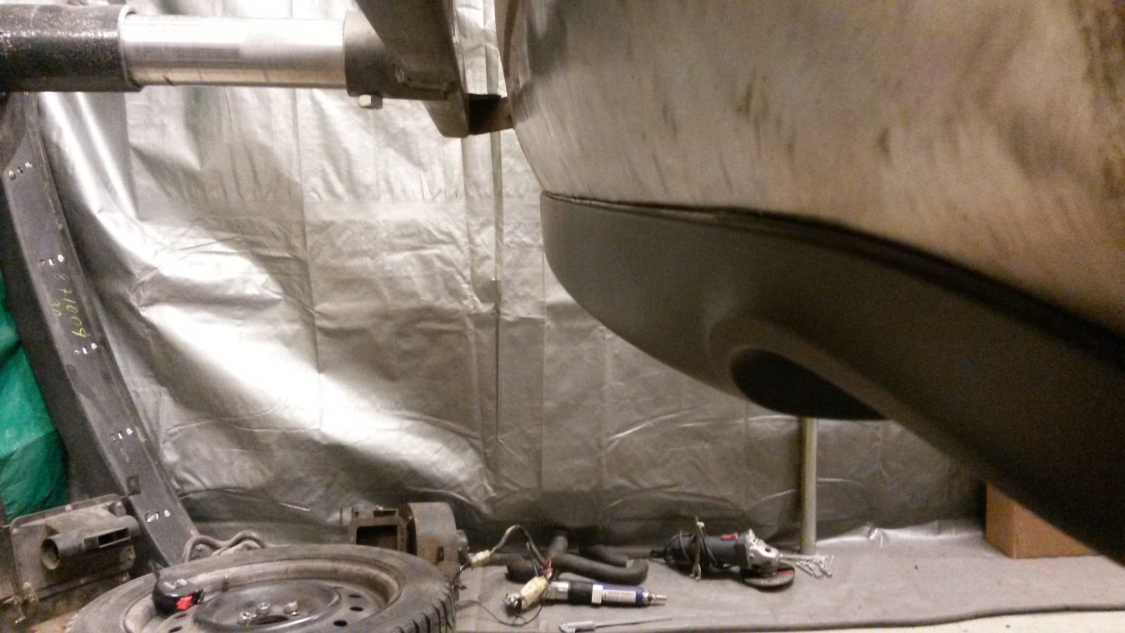
I continued on the Audi diffuser fitment. Managed to get the passenger side pretty much ready.
-
So I've had my eye out for a used intake heat shield on ebay for a while now and finally came across something that fit my criteria. It's a K&N heat shield from a 94-04 Mustang kit. It's very robust stainless steel and required very little modification to make everything fit. I took a gamble on it for $25 bucks and it fits perfectly. Before having a heat shield the filter was about 100* and 120* on the side facing the exhaust manifold. It will be interesting to see how the temps read now.
That's a nice find. I'll have to keep this in mind when I finally get "there".
-
Cool! That is exactly how defined the bends for my exhaust. Except, I made everything from j-bends.
Who did you use to do the CNC bending? How much did they charge.
That looks really good. How long are the primary tubes?
I used a local shop here in town called Martelius Exhausts. Cost was 340€.
The primaries are not equal length, but vary between 800mm-950mm. With the exhaust valve opening angle at 20 degrees before bottom dead center, the tuning of the primaries is roughly between 4000RPM-5000RPM. This is also the area where the engine produces the most torque and this is why I chose to aim for these lengths. Primaries not being equal length is actually beneficial since the torque curve will be more flat as different cylinders have their resonance at slightly different RPM. Better for street anyway.
-
As you can gather from my previous posts, I made a 3D model of the 180 degree exhaust manifolds. From that model, I produced manufacturing documentation for a CNC pipe bending machine. In the documentation, pipes for each cylinder are defined as a series of the following information: straight pipe to be feeded before next bend, rotation of the pipe in respect to the previous bend and angle to be bend. The bending radius is the same for all bends because of the tooling. The material used was 42mm pipe with a bending radius of 70mm. Due to the limitations of the machine, certain consecutive bends are not possible and some extra straight pipe feed is added. This ment that I got a pile of pipes requiring some extensive cutting to the correct lenght and welding. Still much more straight forward since you have a paln to work with. So this is what I got:
The pile includes all pipe work as per 3D model and some extra pipe in the places where two consecutive bends are too close to each other (all extra pipe was marked by the manufacturing shop to ease my work), materials for the collectors along with retaining springs and holders.
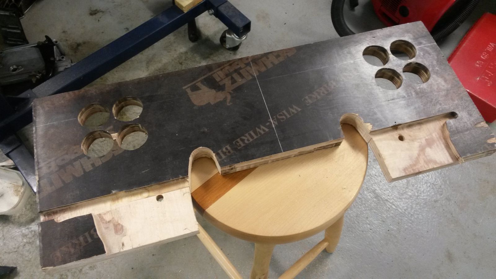
I made a jig to locate the pipes on the collector.
Jig in place.
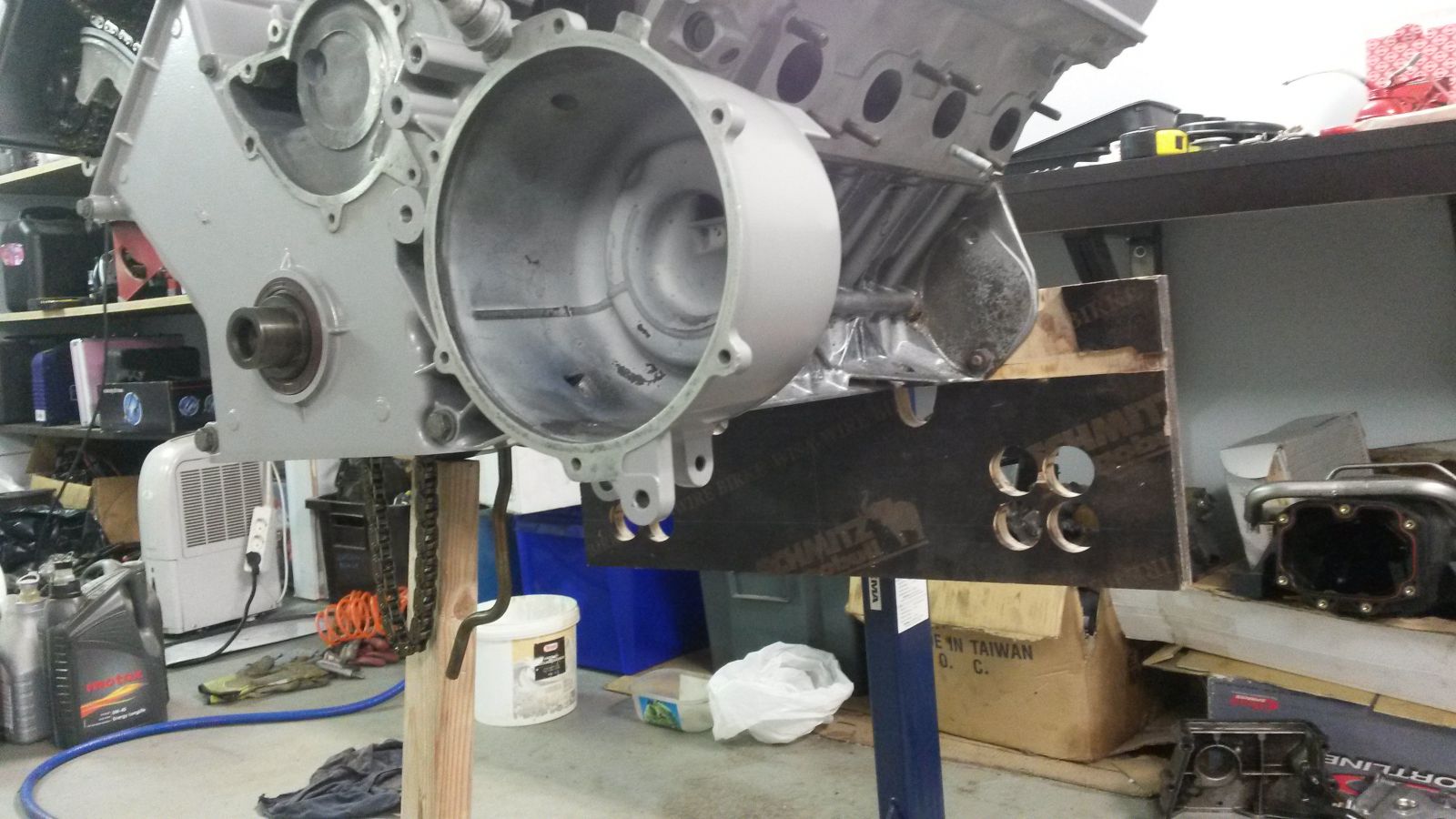
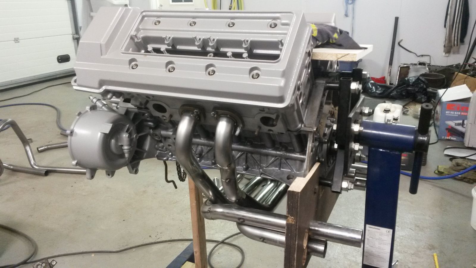
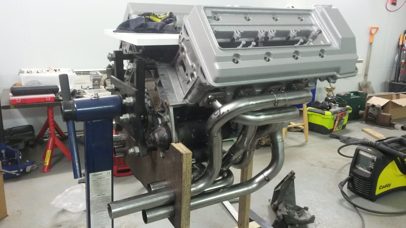
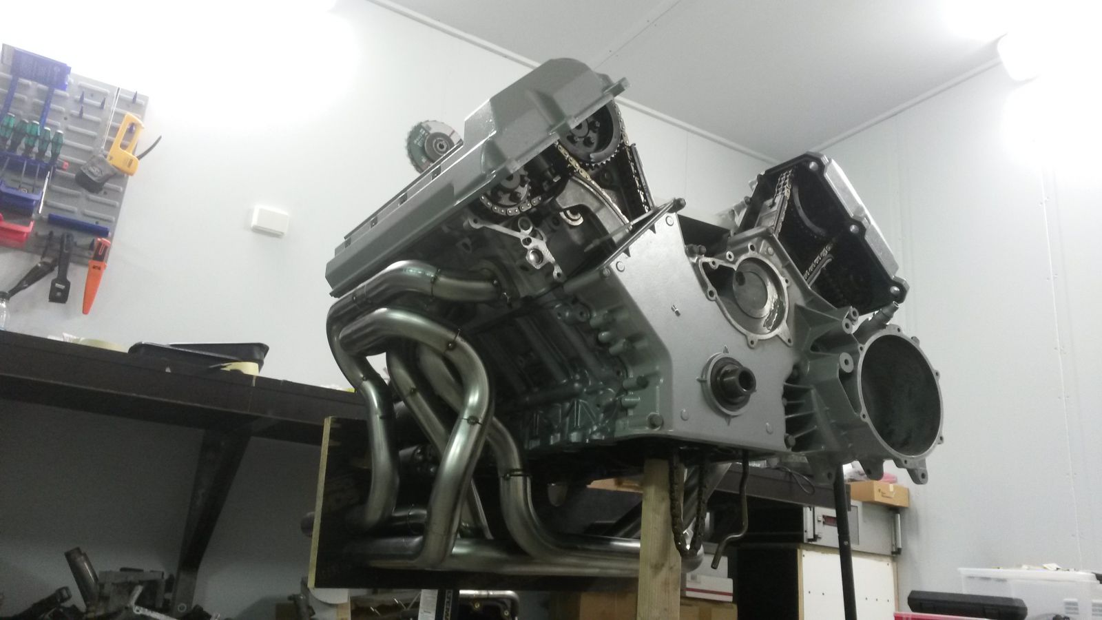
I started with the center cylinders since those are the ones with exhaust pipes running to the other side of the block to combine with their 180 degree counter parts. I now have 6 out of 8 all tach welded in place. I've been working at a "two cylinders per evening" pace.
This is the money shot:
-
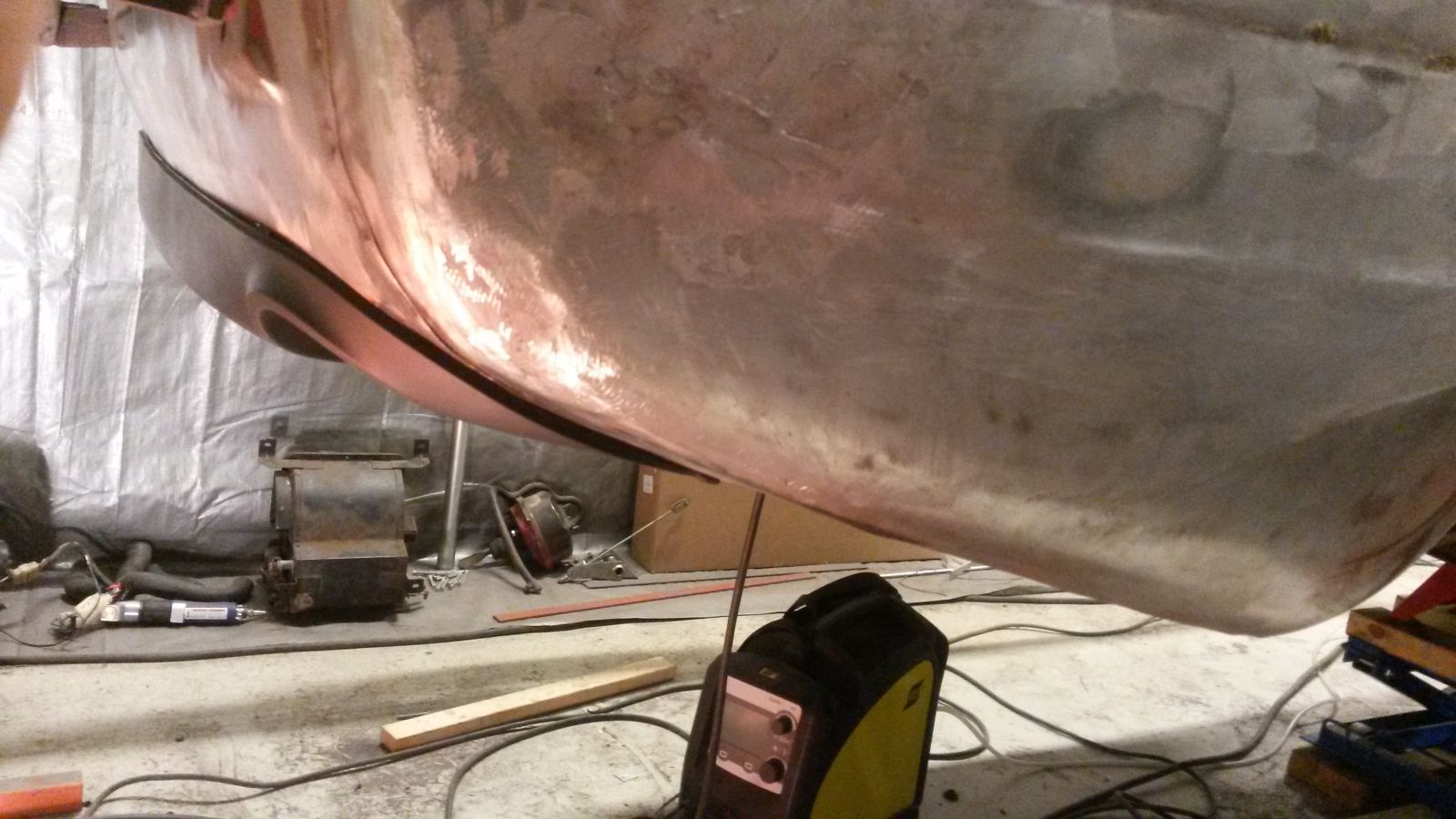
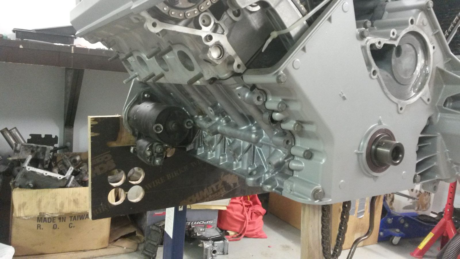
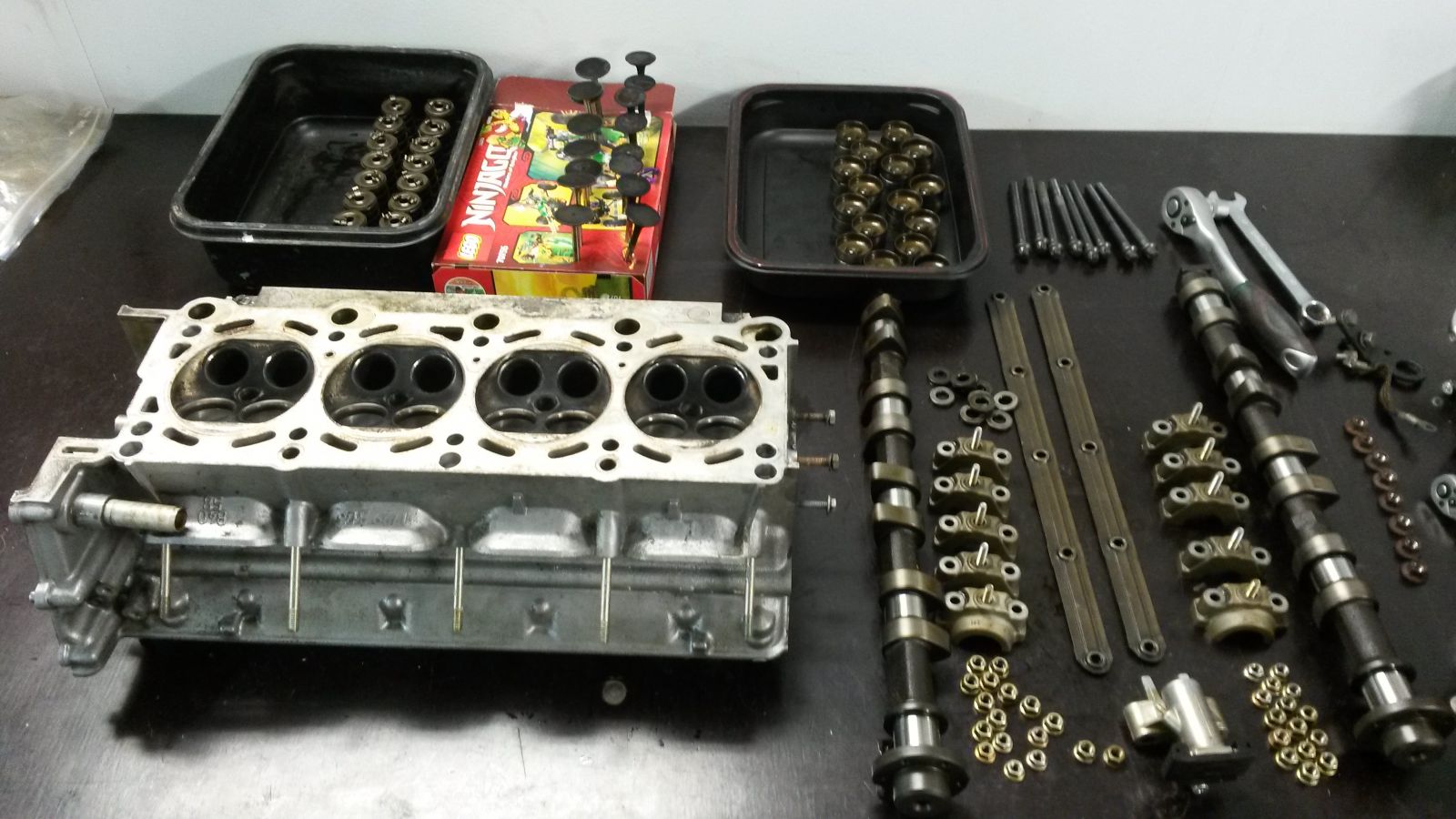
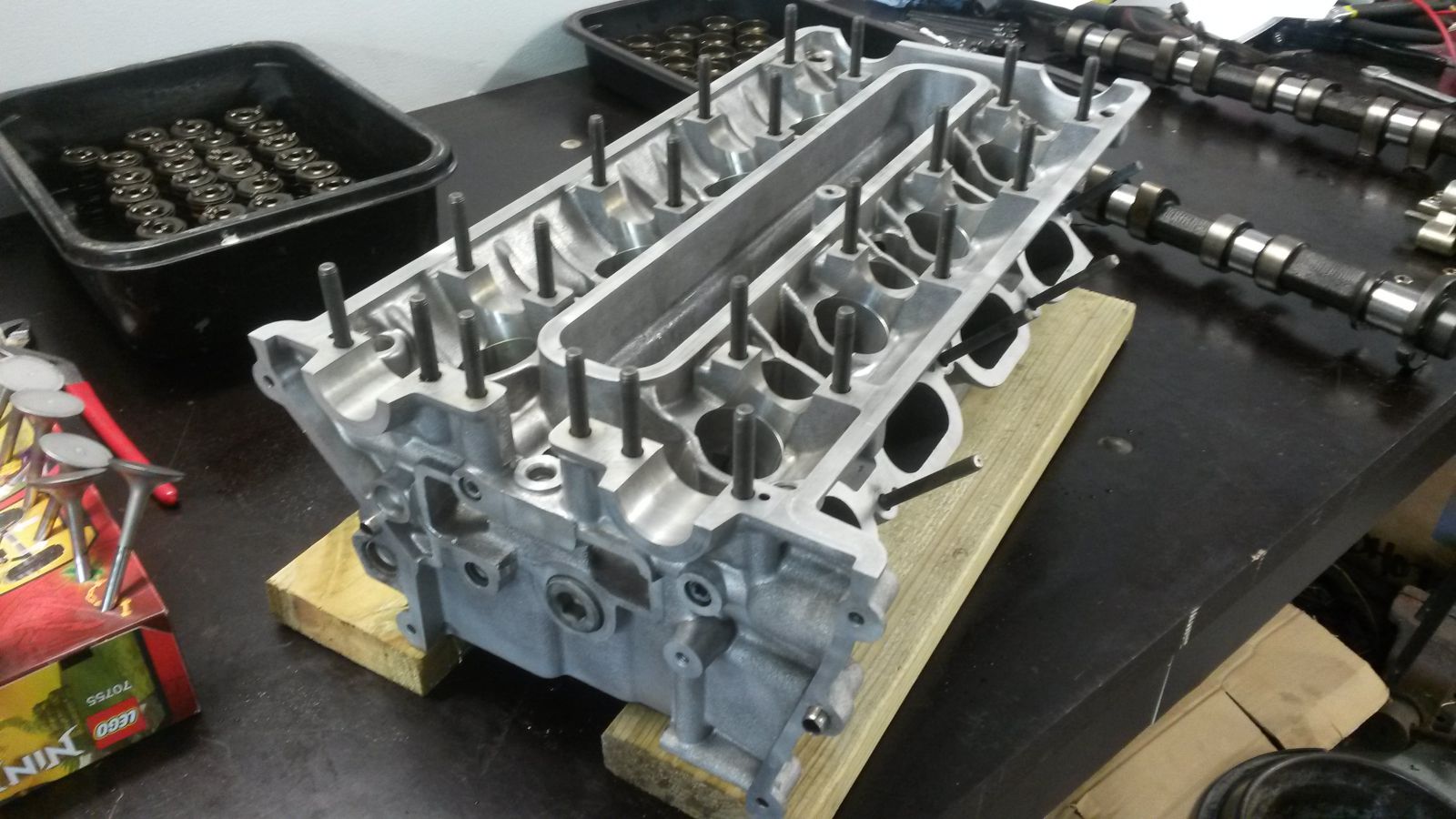
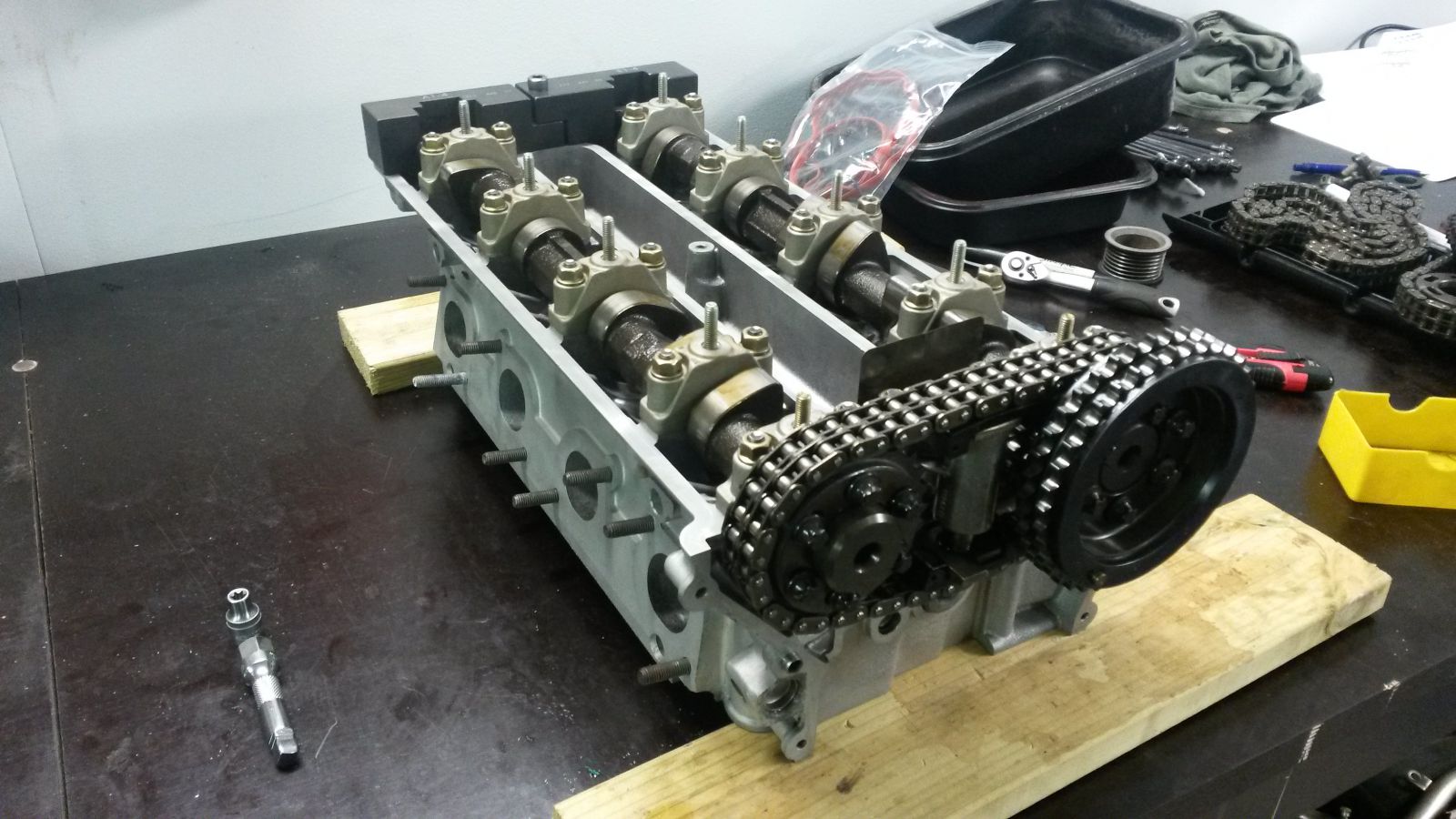
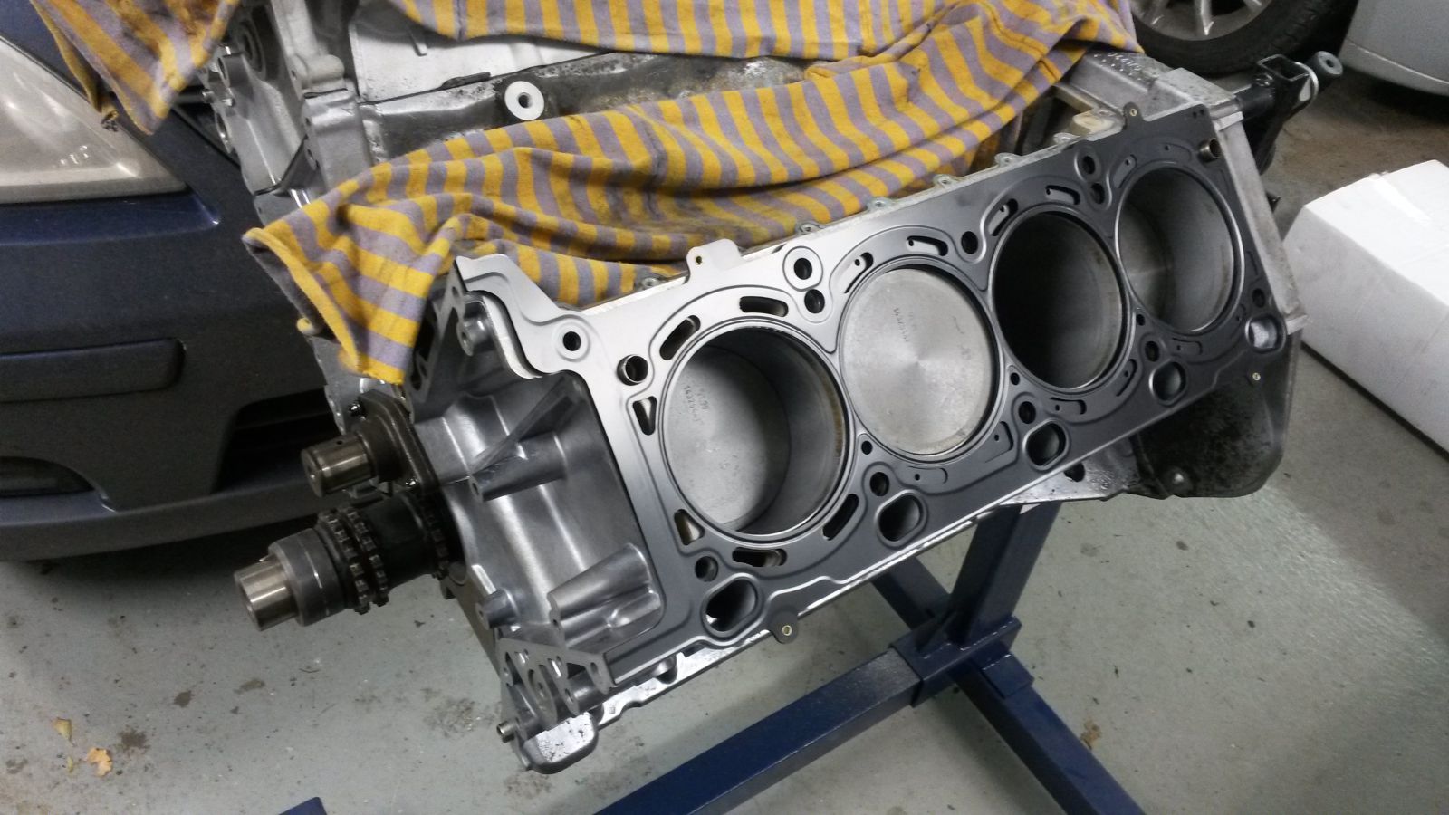
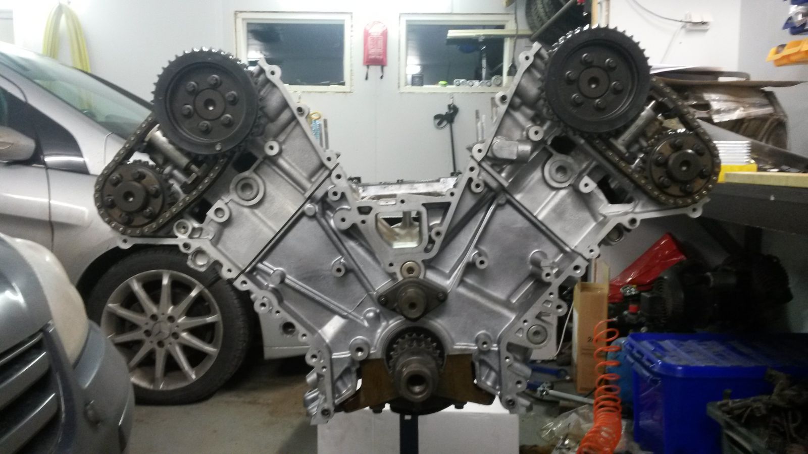
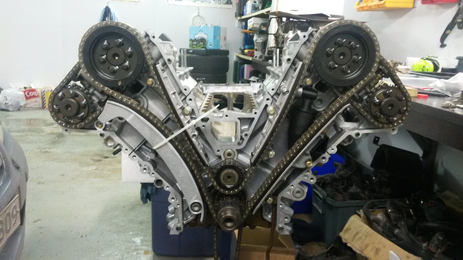
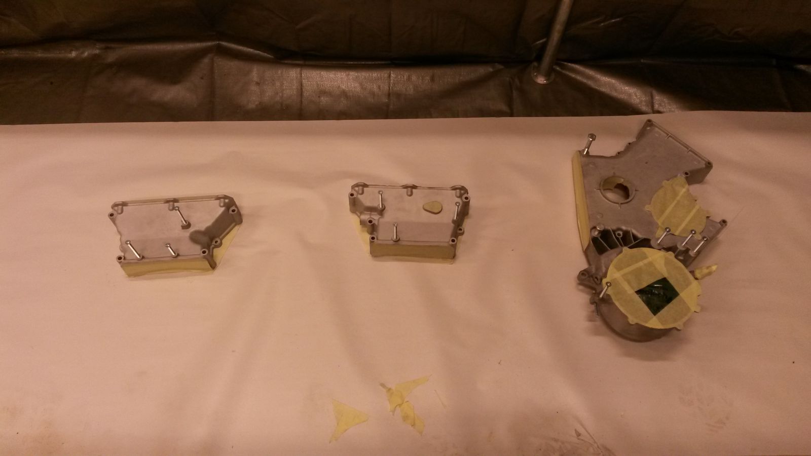
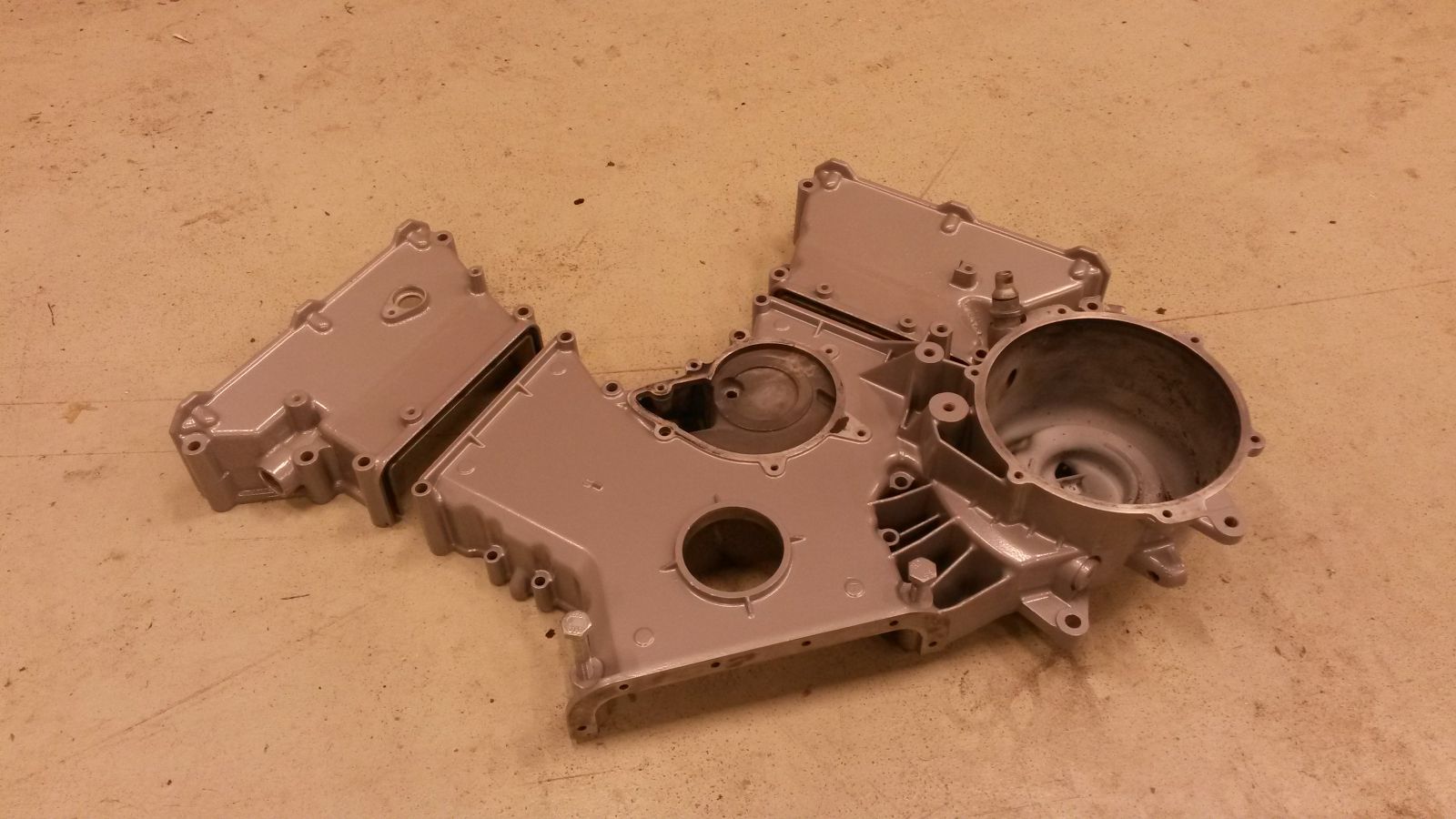
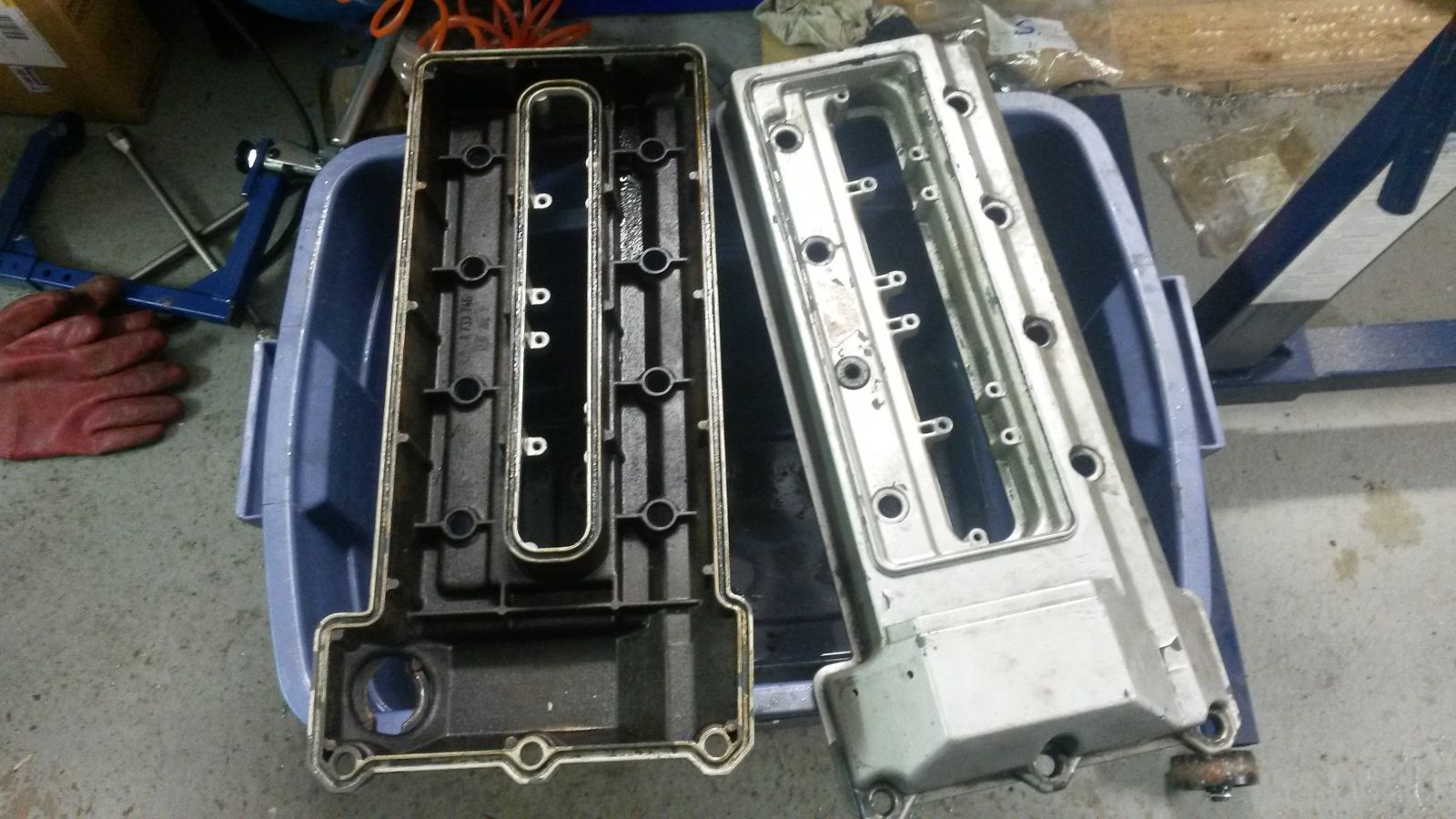
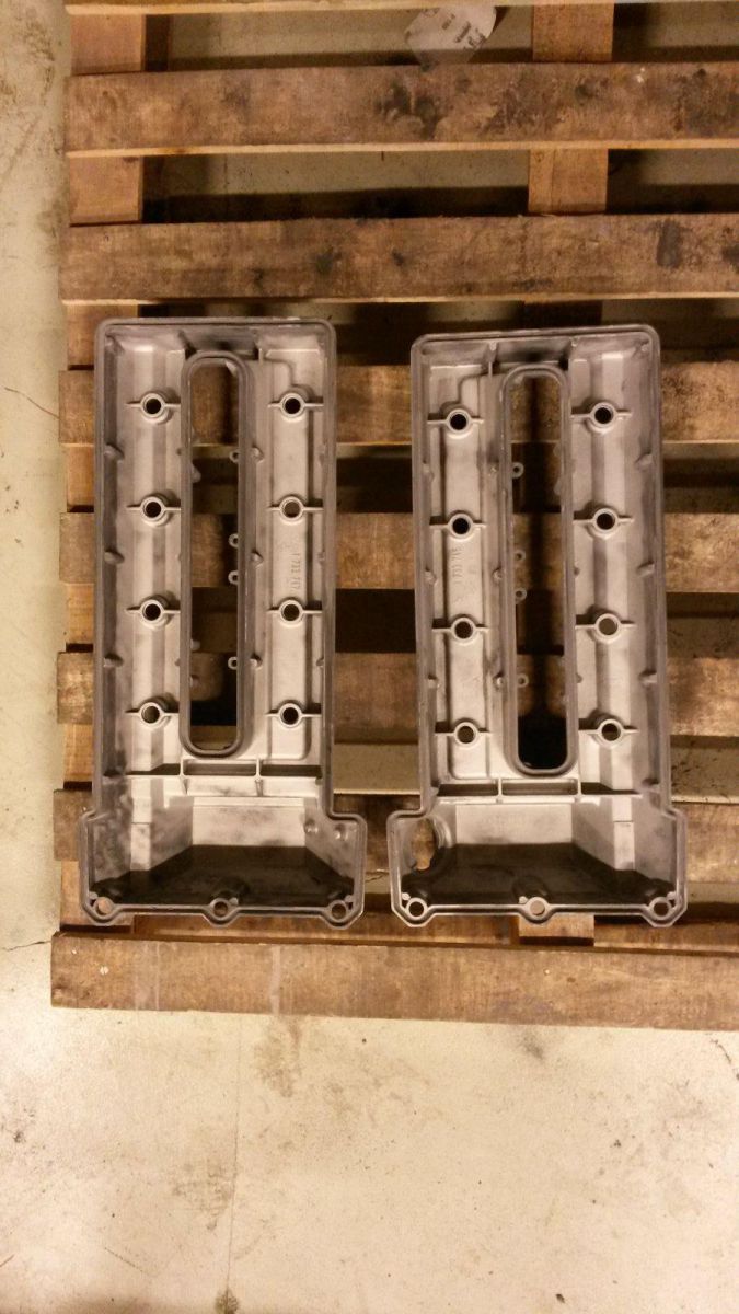
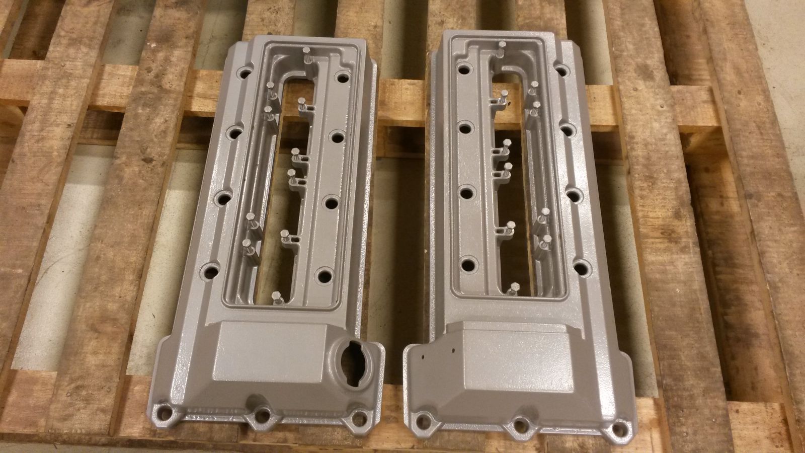
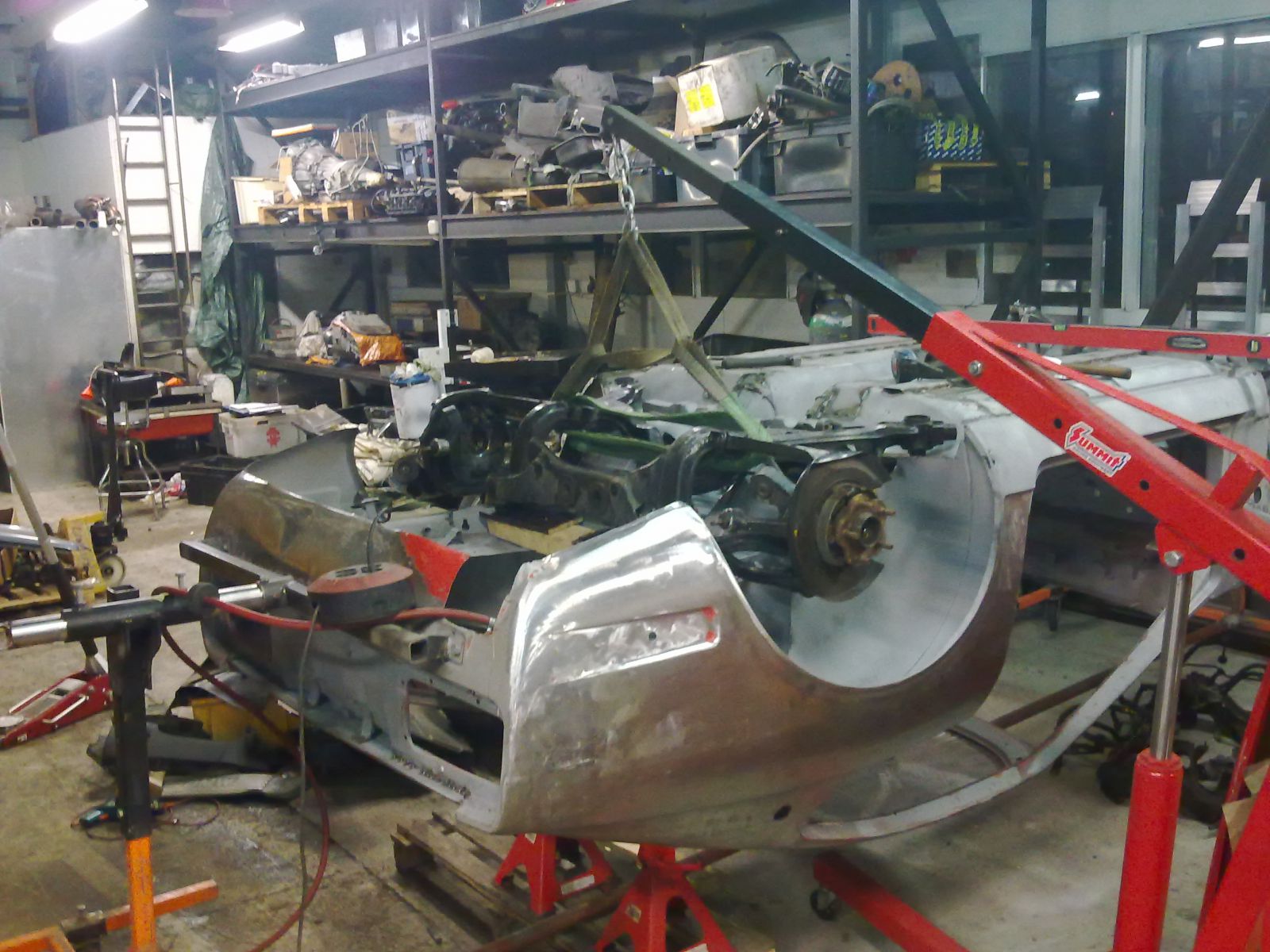
I started fabricating the 180 degree exhaust manifolds so time to get you guys up to speed with my engine rebuild first. I am working on the 240Z at a big shared garage from which I rented a space. While I can only work on the car ever so often, I have been building the engine on the side at my home garage. The rebuild of the engine included a complete disassembly, thorough cleanup, checking the flatness of the head gasget surfaces, all new seals, bearings, head gasgets, head bolts and powder coating the valve covers and front covers.
-
You sure know your way around. My hat goes off to you.
-
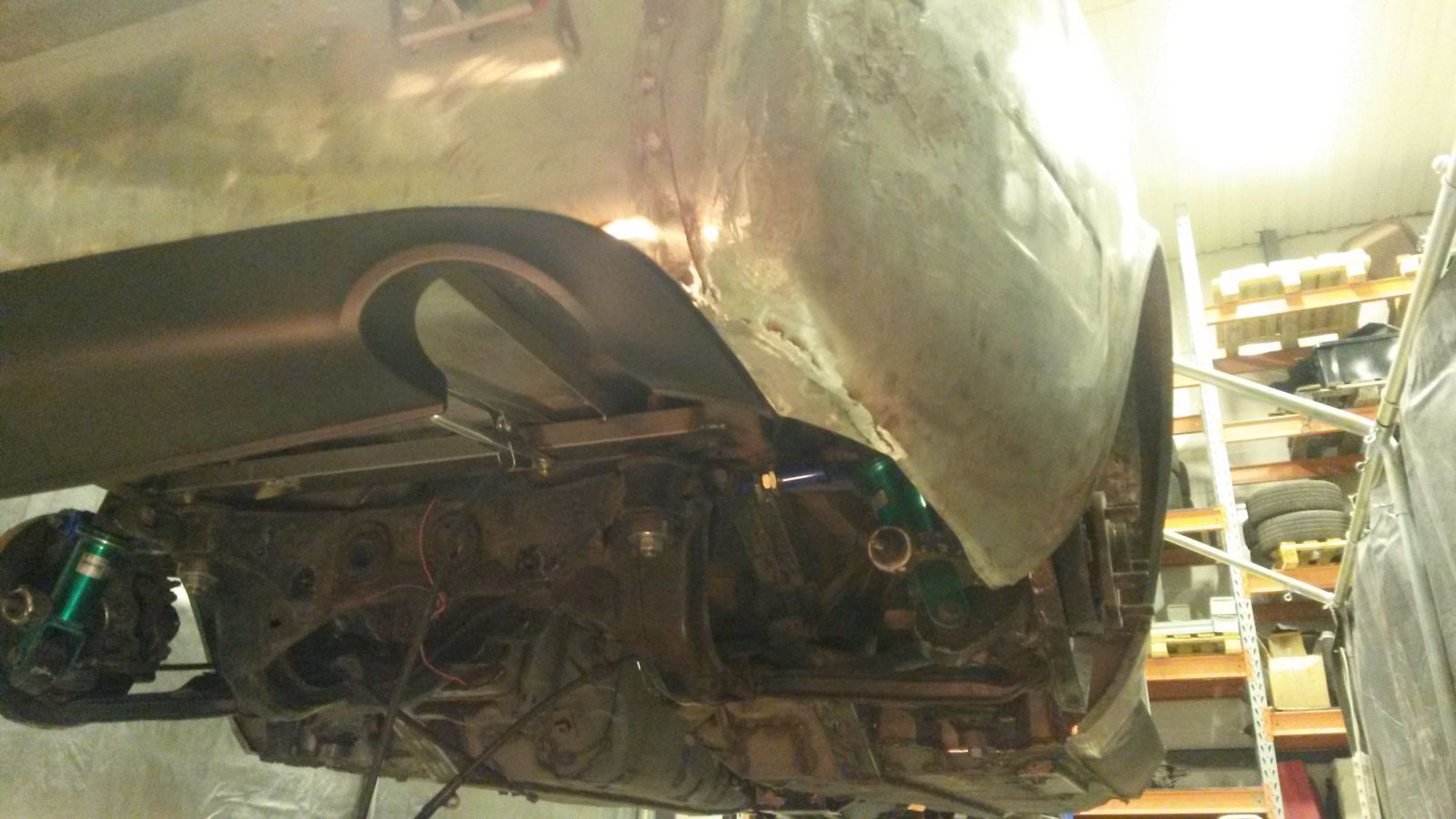
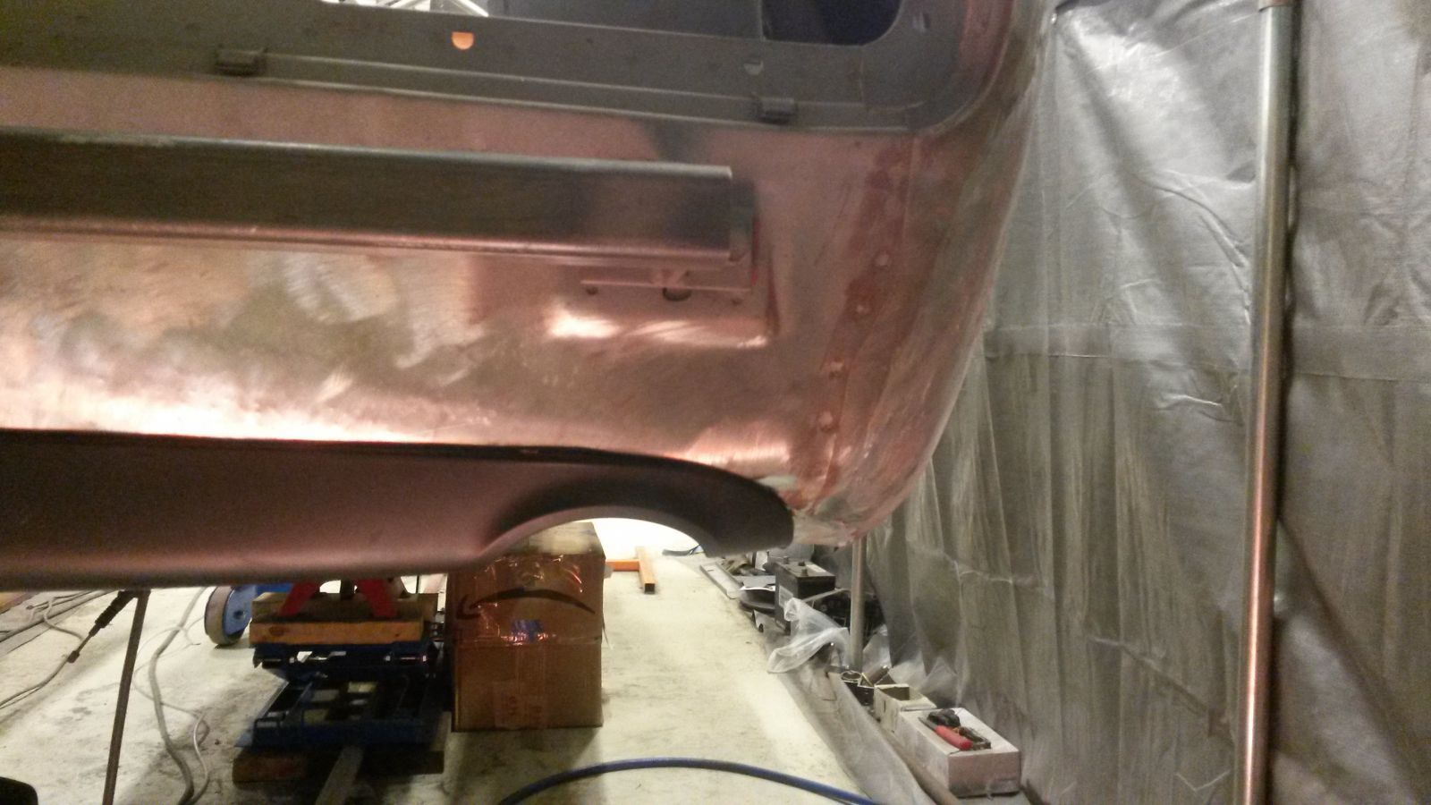
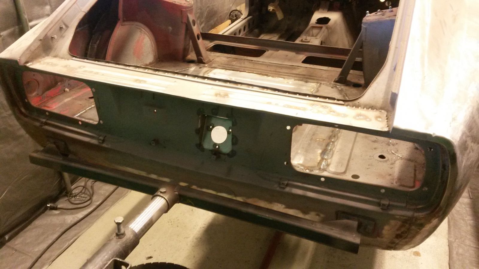
I've been thinking about integrating a rear diffuser from a newer car. One of the obvious reasons for this is that the area below the bumper in my car is totally f#%ked up. Its got huge dents and bents and as a finishing touch, somebody has totally rape the area of the original exhaust tail pipe location with a hacksaw!
An old picture where all this is visible:
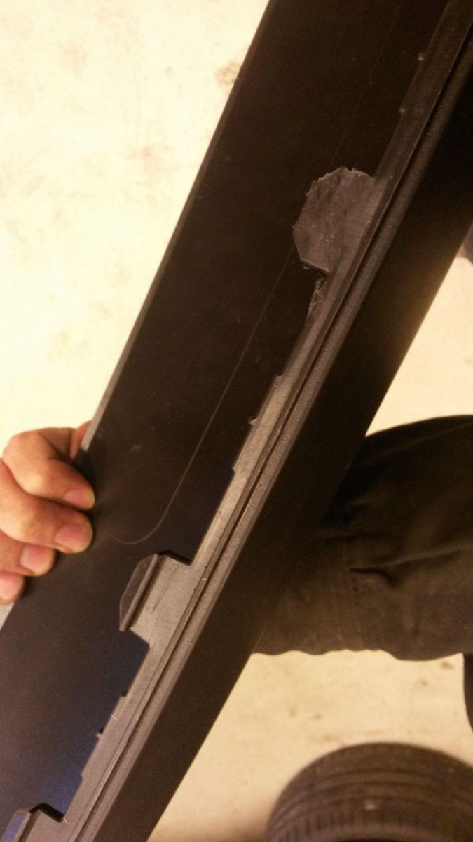
I wanted something subtle with dual exhaust and after several hours of searching on the internet and constantly looking at rear diffusers on parking lots etc. I finally decided to go with an Audi A4 B6 unit. The curvature of the part is definitely not the perfect match off the shelf since the rear of the 240Z has only a slight curvature, but after some minor modification, the fitment was surprisingly good. The OEM Audi part is a made of plastic and this is a key point to notice. There are good looking carbon fiber tuning parts for Audi, but they simply wont fit the 240Z. The plastic part can be forced to follow the shape of the 240Z rear.
This is the diffuser I used:
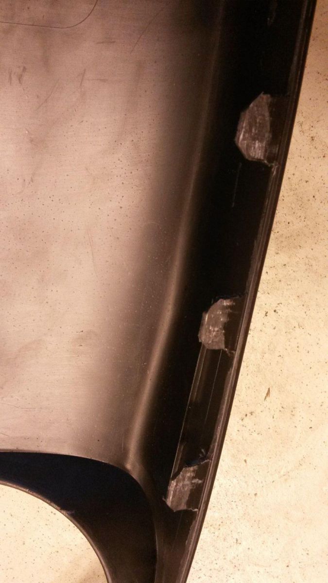
In the Audi, this part is attached to a plastic bumper. The orignal retaining scheme needed to be modified. Also some reinforcement plastic needed to be removed so the part will bend more easy.
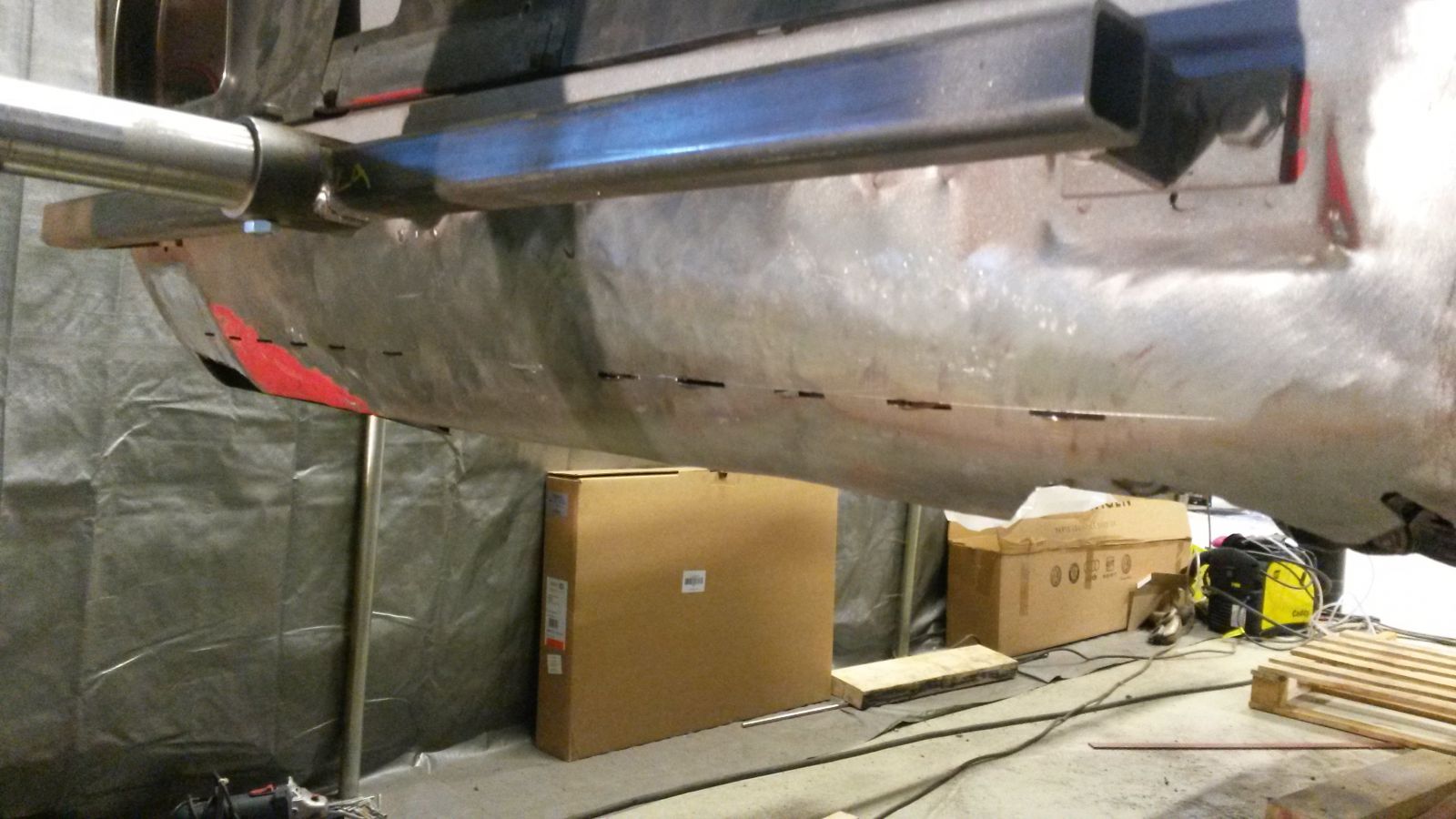
I made these rectangular shaped cuts to the rear valance where the diffuser is to be attached. The diffuser is fixed in place with metal clips from the back side (I forgot to take a picture of those clips).
The fitment is already quite good although I did not fix the part with the retaining clips yet in these next photos. I still need to fabricate some sheet metal to the sides. There is also a screw hole on the side of the diffuser so I need to make a bracket for that inside rear quarter panel. I plan to weld a small-diameter metal bar along the top seam of the diffuser to create a sort of lip above the diffuser which is going to sit flush with the surface of the diffuser. The metal bar is then bondoed to the sheet metal so that everything integrates together nicely. My new fuel inlet location is also visible in these pictures.
-
I believe that is a heater core for a "no A/C" model. The pressure of an A/C system is considerably higher, so using a heater core as an evaporator might be risky.
-
While trying to prep all the small details and fixing points to the body to get this thing finally undercoated, I am aiming to tackle some upcoming challenges of the build.
I am planning to install an AC-system to the car and I think all other stuff is going to be straight forward, but the evaporator core is giving me a headache.
Here you can see the heater box of the 240z:
I believe there is room under the dash to bring the air routing scoop (the part in front which is bolted on the rest of the unit) outwards. The plan is to make a spacer and locate the evaporator core in between the scoop and the rest of the unit. While doing this, the scoop attached to this part which routes the air to the midlle air vent on the dash needs to be cut into suitable lenght, but that seems to be doable.
The problem is to find a small enough evaporator core. The ideal dimension would be 120mm x 200mm with which, the original fixing points for the scoop could be retained.
Does anybody have an idea where I could find a core this small?
-
So you´re going to hide gas filler under licence plate? I thought that too, but not decided yet. What kind of hinge you have in mind for licence plate?
Yes, that's the plan. I ordered a license plate fuel door such as this from ebay:
But I doubt I am going to use that for it requires some modification. The height of our license plates here in Finland is smaller than the US plates so it would look goofy without modification. Also, the plate does not sit flush on the surface with the door I got.
I am probably going to make my own custom bracket/door. One idea is to make the plate slide to the side and uncover the fuel filler cap. If I remember correctly, there is just enough space to slide the plate aside.
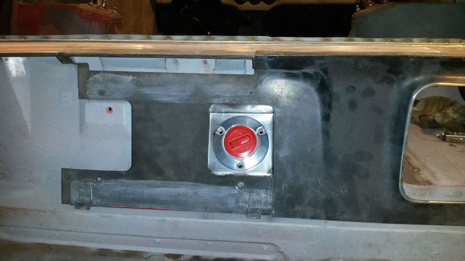
The fuel filler neck I got is a maritime item ment to be mounted on the deck. It has an O-ring seal on the cap, which I think is a must in this installation.
-
Thanks ditto64! It is nice to get an interception on the monologue for a change.
I was not too so happy with the original wiring harness fixings and a lot of them had cracked loose so I decided to replace them with something new. I am using some Audi fixings.
I made these little brackets which are tack welded in place and the cable fixing is going to be slipped on the bracket.
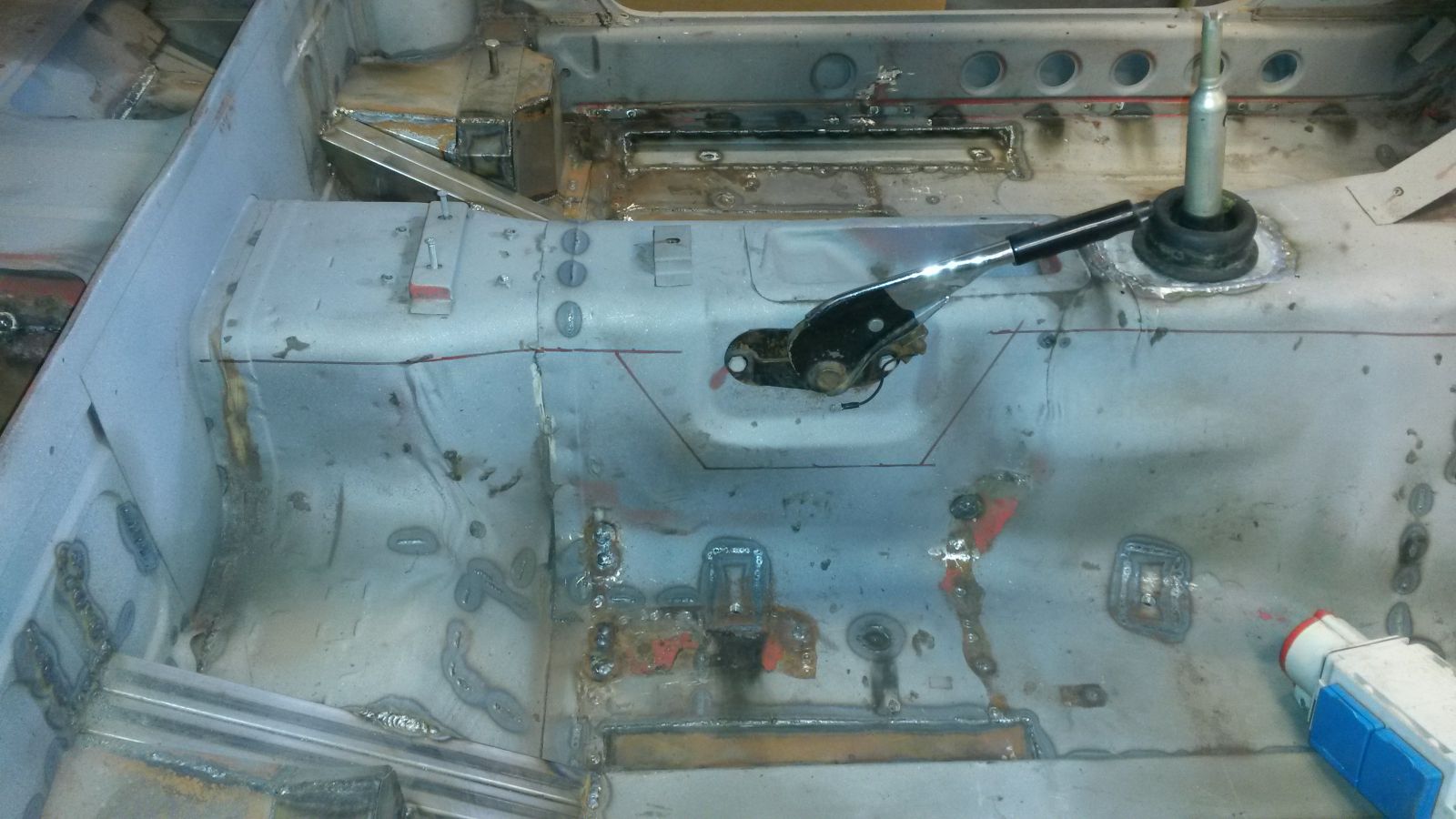
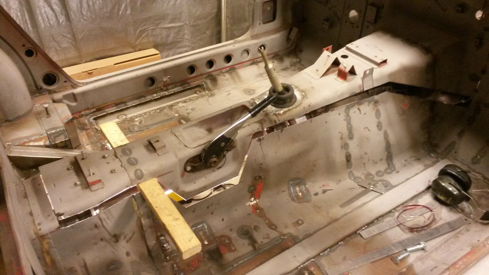
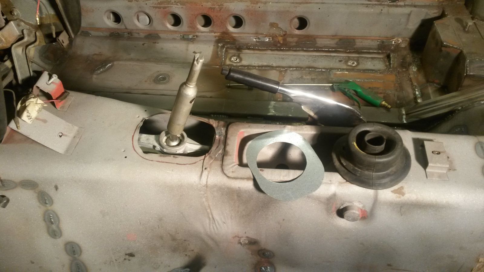
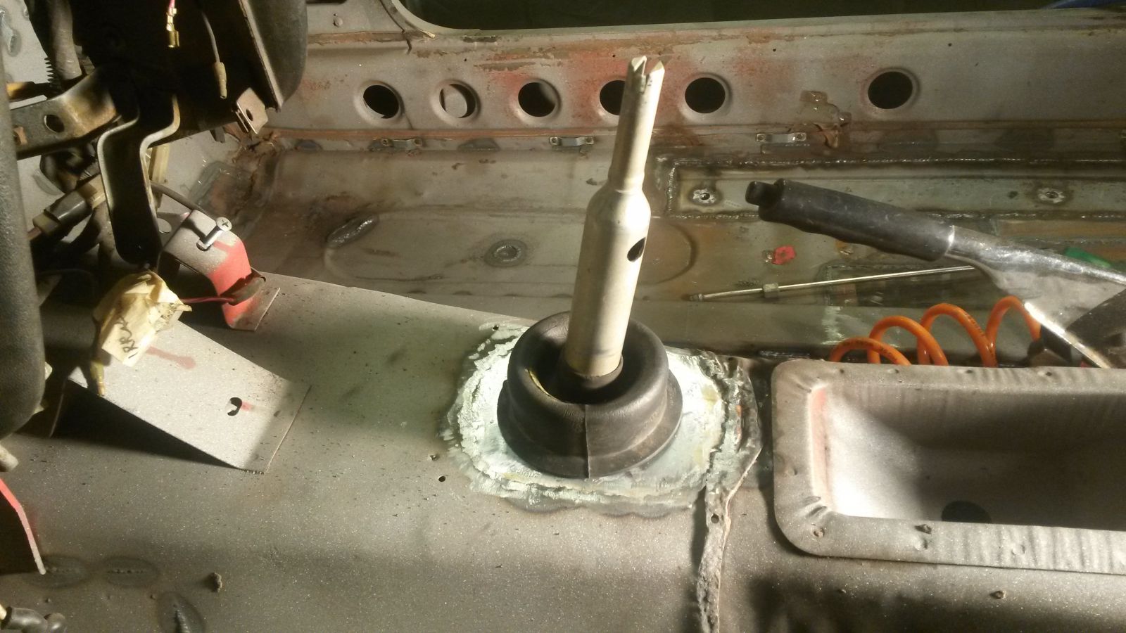
Also continued on the BMW shifter retrofitting. The shifter has a nice rubber boot to seal the hole and prevent any dust from entering the cabin. I cut the hole on the tunnel a little bigger and cut a suitable sheet metal piece with a right diameter hole on it for the boot.
Ready to be welded:
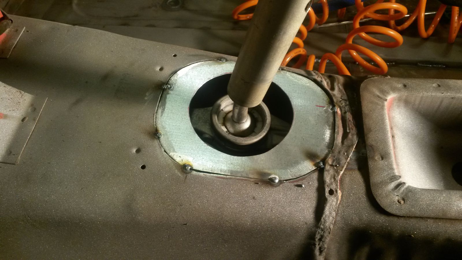
With the new piece tack welded in place, I checked the alignment with the stick. Nice and center:
Here is the finished assembly:
-
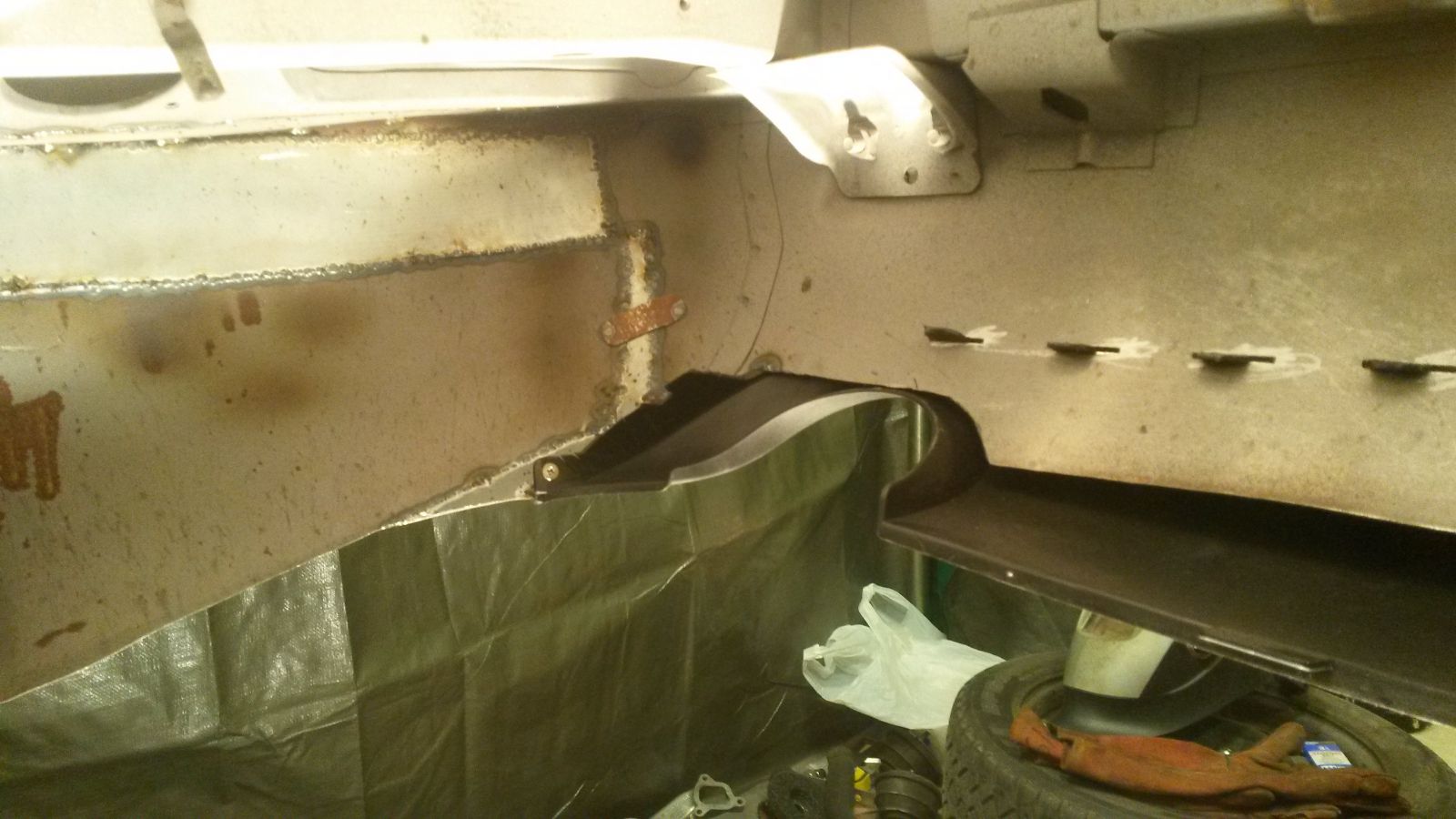
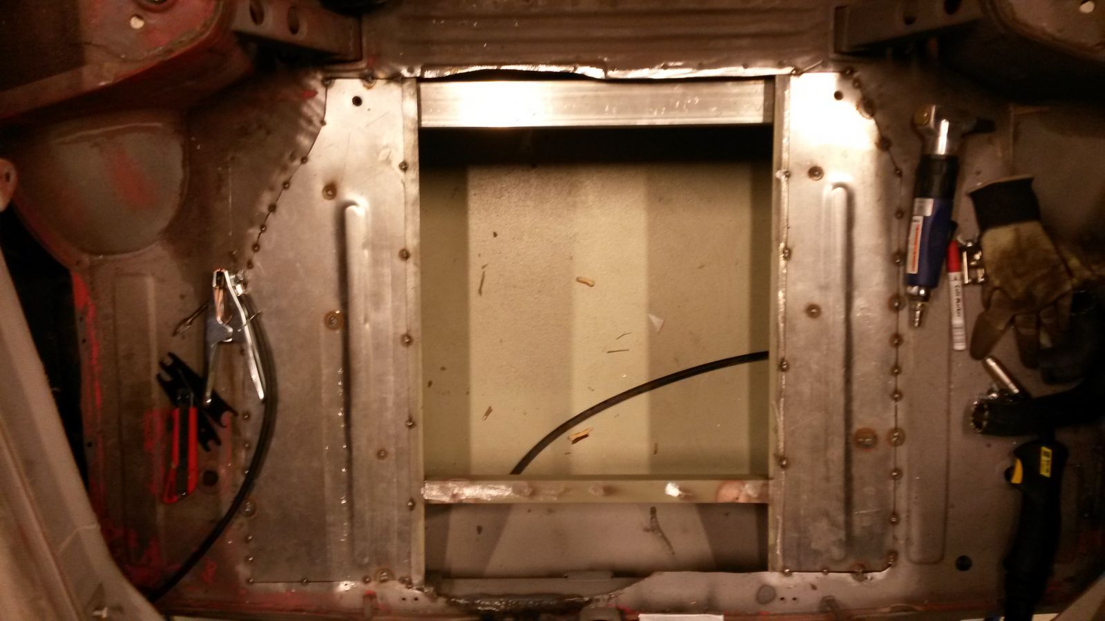
Did some sheet metal work on the rear compartment floor. I made a custom dimple die to use with a hydraulic press to get some stiffness to the new floor panel. Here is the proof of concept test piece:
I made the new floor pan from three pieces. The reasons are many: It would have been inpossible to fit the whole piece between the poles of my hydraulic press, I did not have a big enough piece handy and also it was quite convenient to section the pieces along the fuel cell frame rails and weld them on the rails. Work in progress:
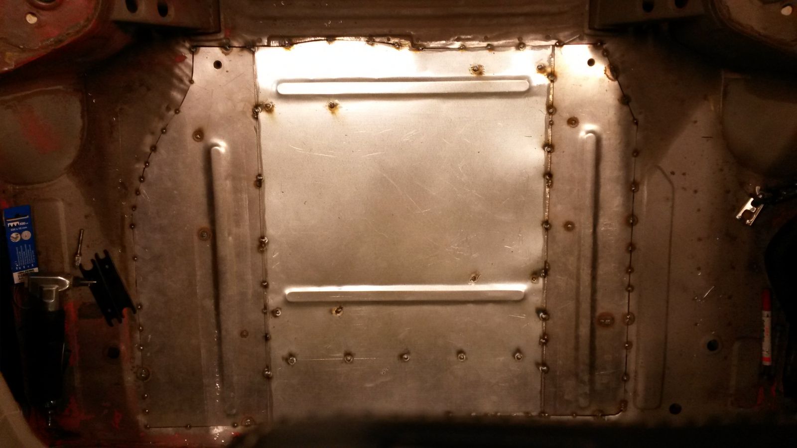
All three pieces tack welded in place:
Here's the finished floor with fully welded outer edges and some long stiches along the fuel cell frame rails (Also a sneak peak at my new fuel filler neck location):
-
Could you post up a video of the sounds. Looks very nice, but probably loud.
-
The car looks super good!
Can you post your ground clearance and wheel spec here:
http://forums.hybridz.org/topic/125395-whats-your-ground-clearance/
-
I need some help figuring out the feasibility of my prop shaft concept. The distance between the transmission output shaft flange and the differential input shaft flange is 826 mm so no point in including a center bearing like the GTR shaft incorporates. There are two identical CV-joints and a single U-joint to work with. The CV-joints allow some movement along the axle where as the U-joint is obviously fixed in length. The natural way to go about this would be to put the U-joint in the transmission end and one of the CVs in the diff end as it fits right in. The problem with this approach is that the adapter flange to the transmission end will have intercepting screw location when using the U-joint. Another approach would be to use the second CV-joint at the transmission end because the holes to the adapter flange happen to align perfectly without any interceptions. The problem with this approach is that both ends of the prop shaft will allow longitudinal movement, meaning that the shaft will float in between the joints. My question is, will this floating create a problem? I did some research and found that atleast Honda S2000 AP1 has CV-joints on both ends of the prop shaft and the joints seem to be identical. Also based on some youtube videos of the shaft, they both seem to allow longitudinal movement.
Here is a picture of the S2000 prop shaft. Mine would look exactly the same.
-
My most recent agenda with the car was to retrofit the BMW gear lever to the 240Z.
Here is the BMW assembly.
I took it apart, cleaned the bits and meadia blasted.
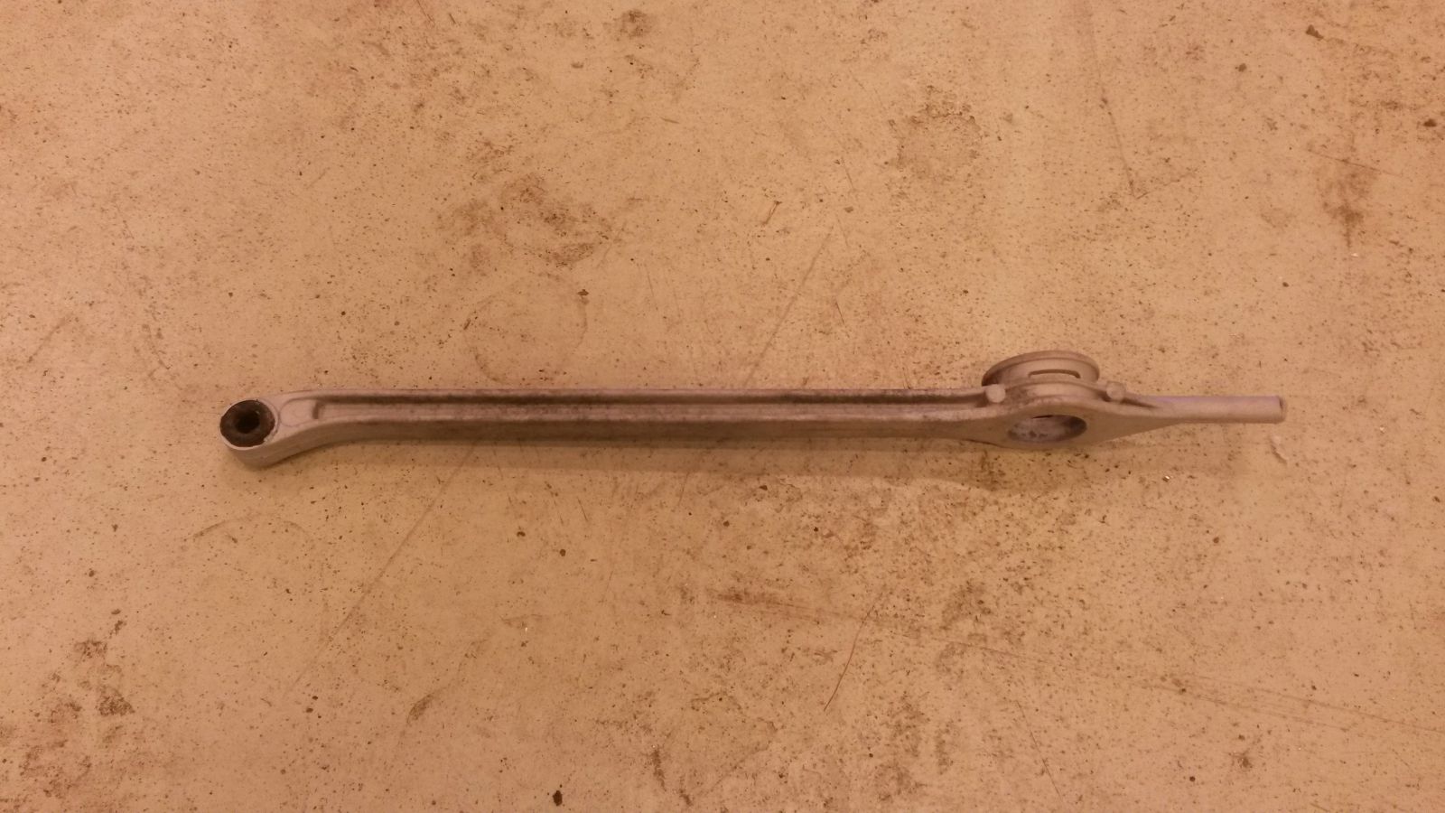
As the engine sits quite near the firewall, the gear box goes well into the transmission tunnel. In order to get the shifter to stick out from original position, I cut the support arm into lenght and went at it with a TIG welder. Is this what they call a short shifter or am I missing something here?
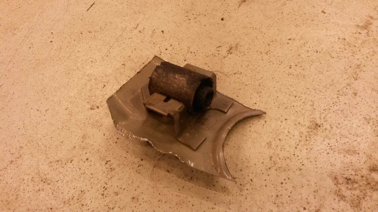
The back end of the support arm goes into a bushing in the transmission tunnel. I went and cut out the bracket and the bushing from a wrecked up E39.
I cut the excess stuff out and drilled some fixing holes to the bracket. Then I bolted two M6 distance nuts on the bracket Which are welded into the tunnel.
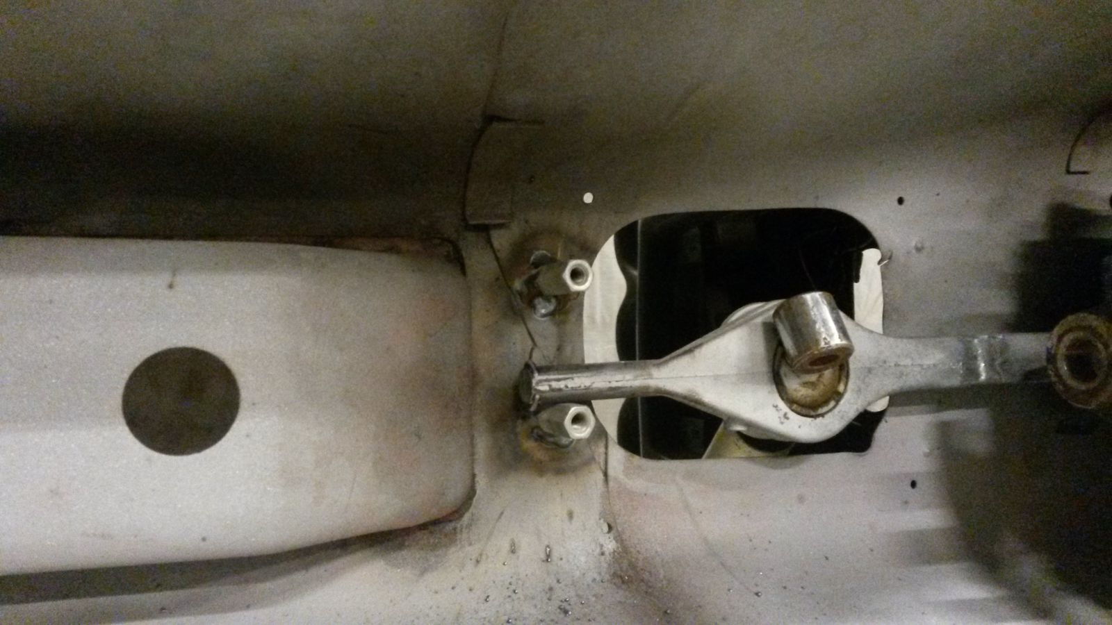
Distance nuts welded in.
The support arm in place with the bracket bolted on the distance nut.
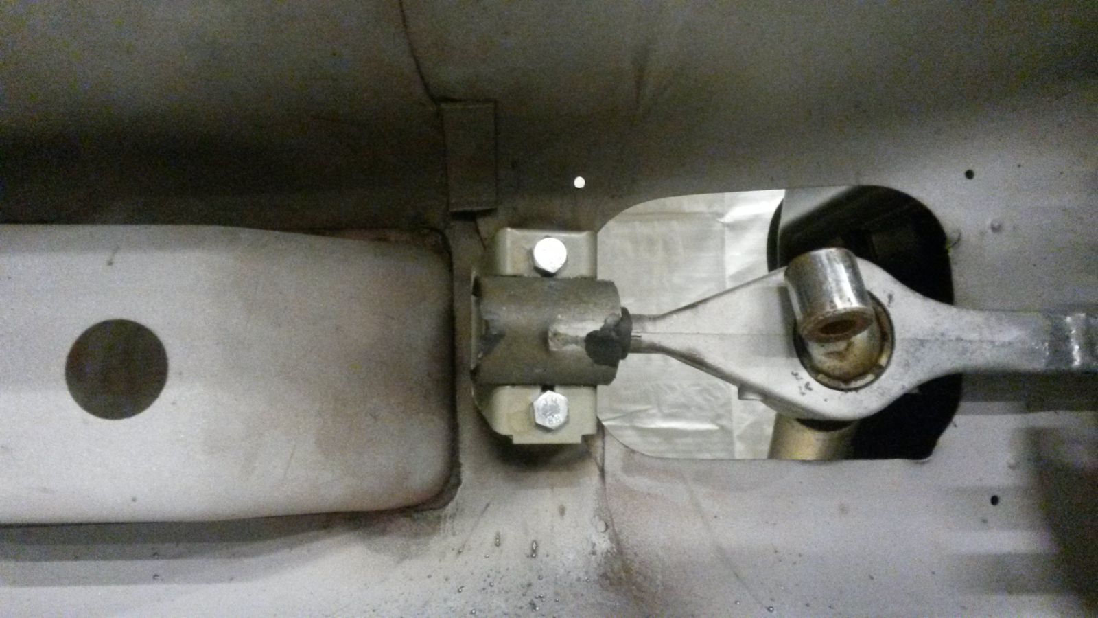
The shifter lines up nice and center. I will still have to cut a piece of sheet metal in there which will be welded into the original hole and which will have a round smaller diameter hole to take the rubber seal depicted in the first picture of this post. Also the actual axle changing the gears will have to be cut to lenght and bolted on.
-
That AC condenser looks to be a very nice fit. Any change you could share where that can be found? Size and possibly a part number would be great.
The car looks amazing, congratulations!
-
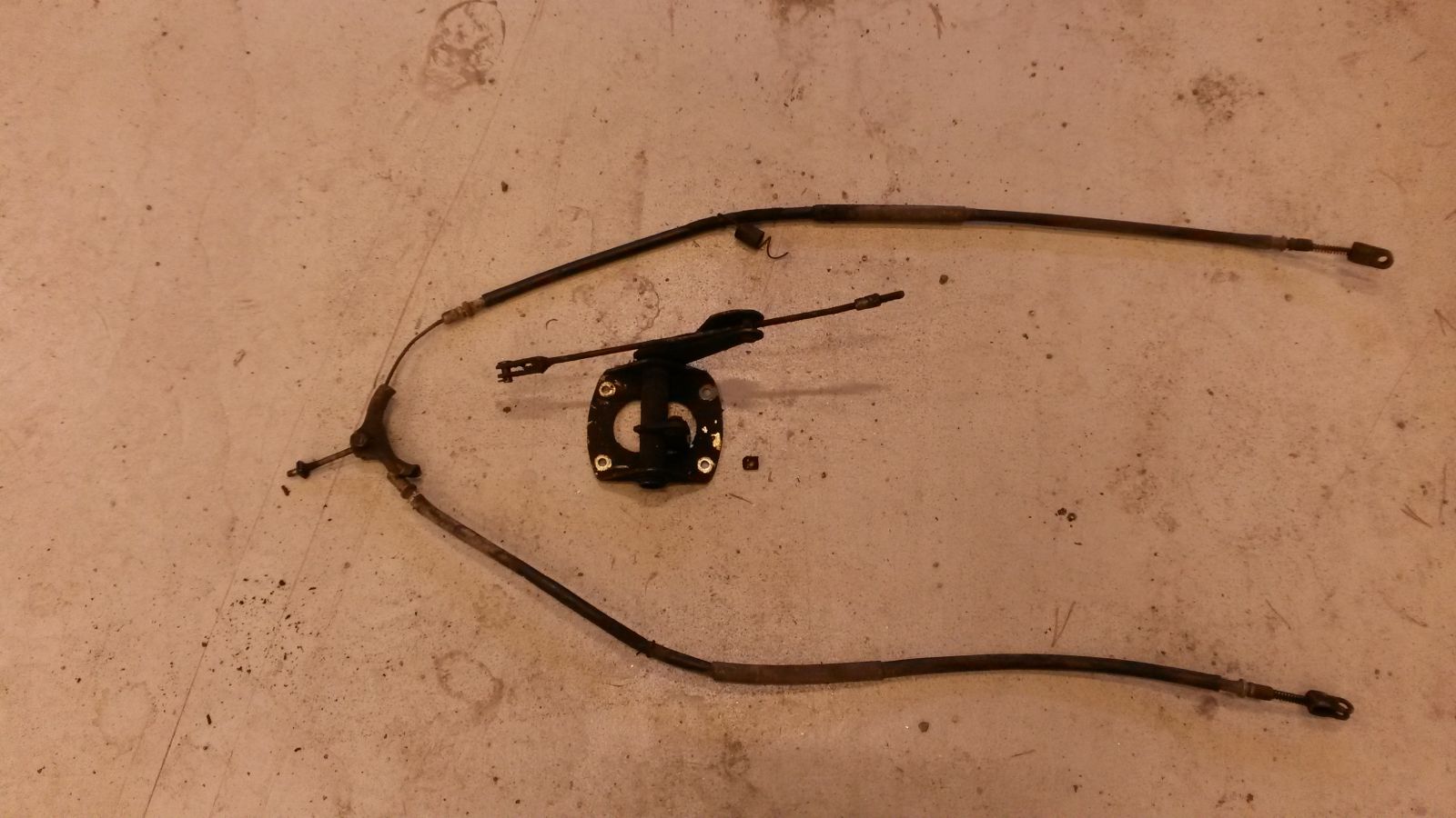
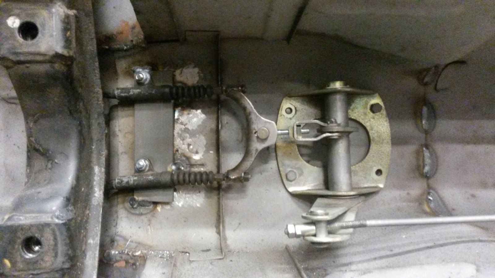
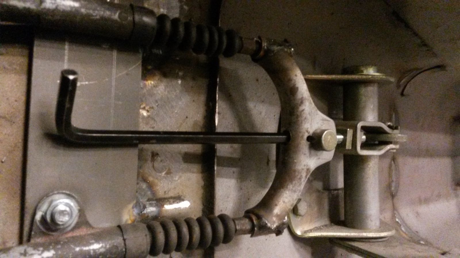
Time to update on some of the latest progress. With the handle of the parking brake in place, I decided to clean up the rest of the original parts associated and check out what was required to mate the GTR-32 parking brake cables to the mechanics of the 240Z parking brake. And to the photos:
Here are the super dirty parts before cleaning
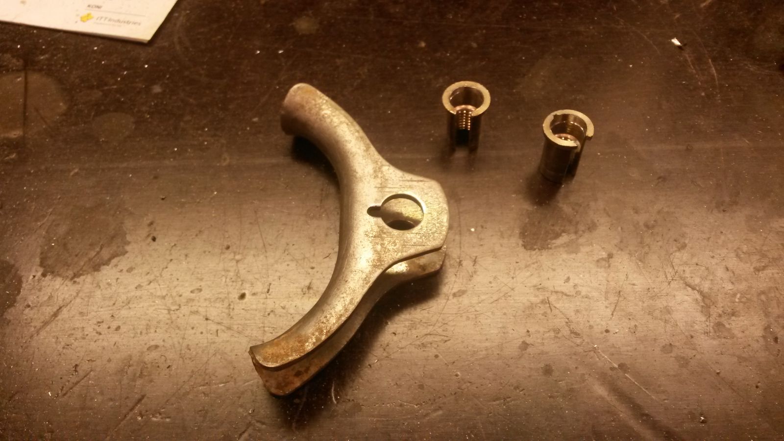
Turned out quite nice after some cleaning and brushing. I used turpentine as the cleaning agent.
I noticed that the inner diameter before the thread of a thread insert/sleeve was just right for the knob of the GTR-32 cable so I fabbed the cable puller from those.
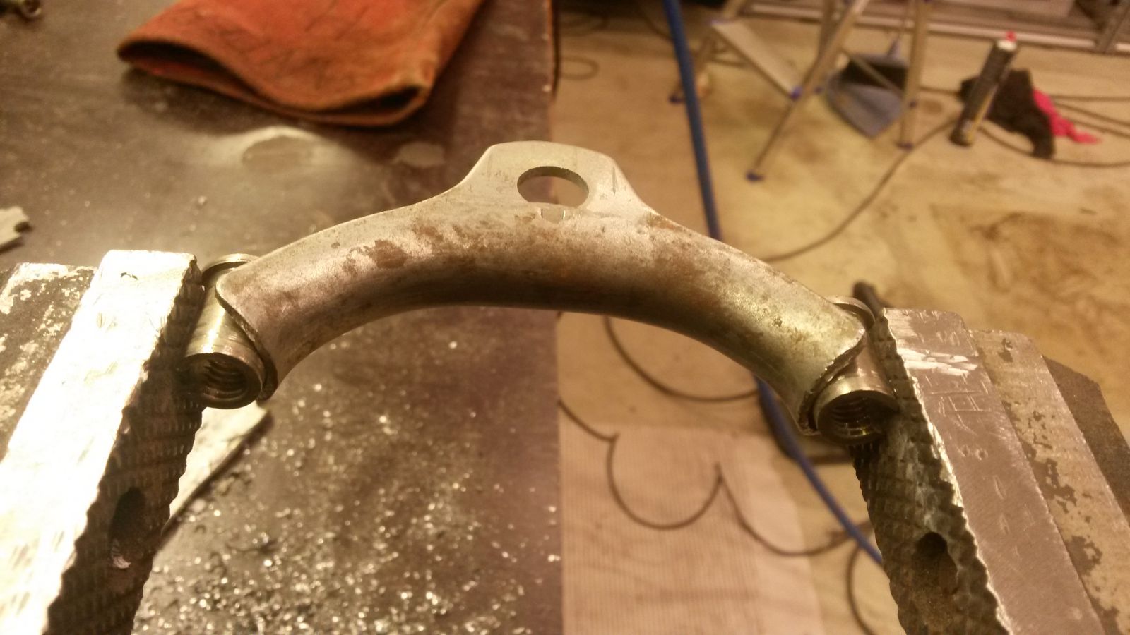
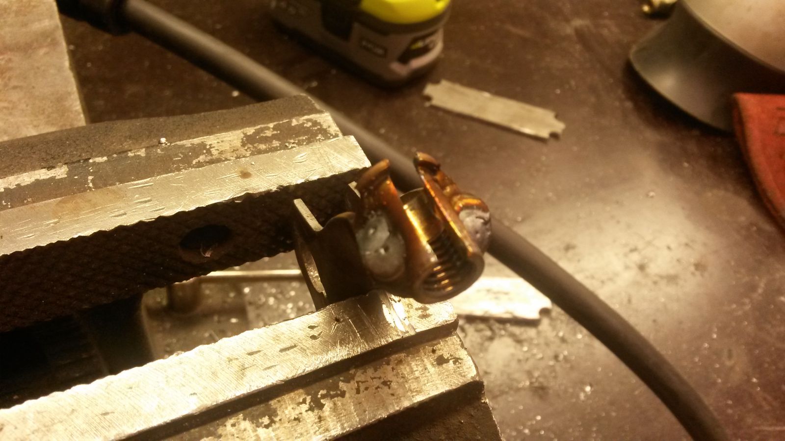
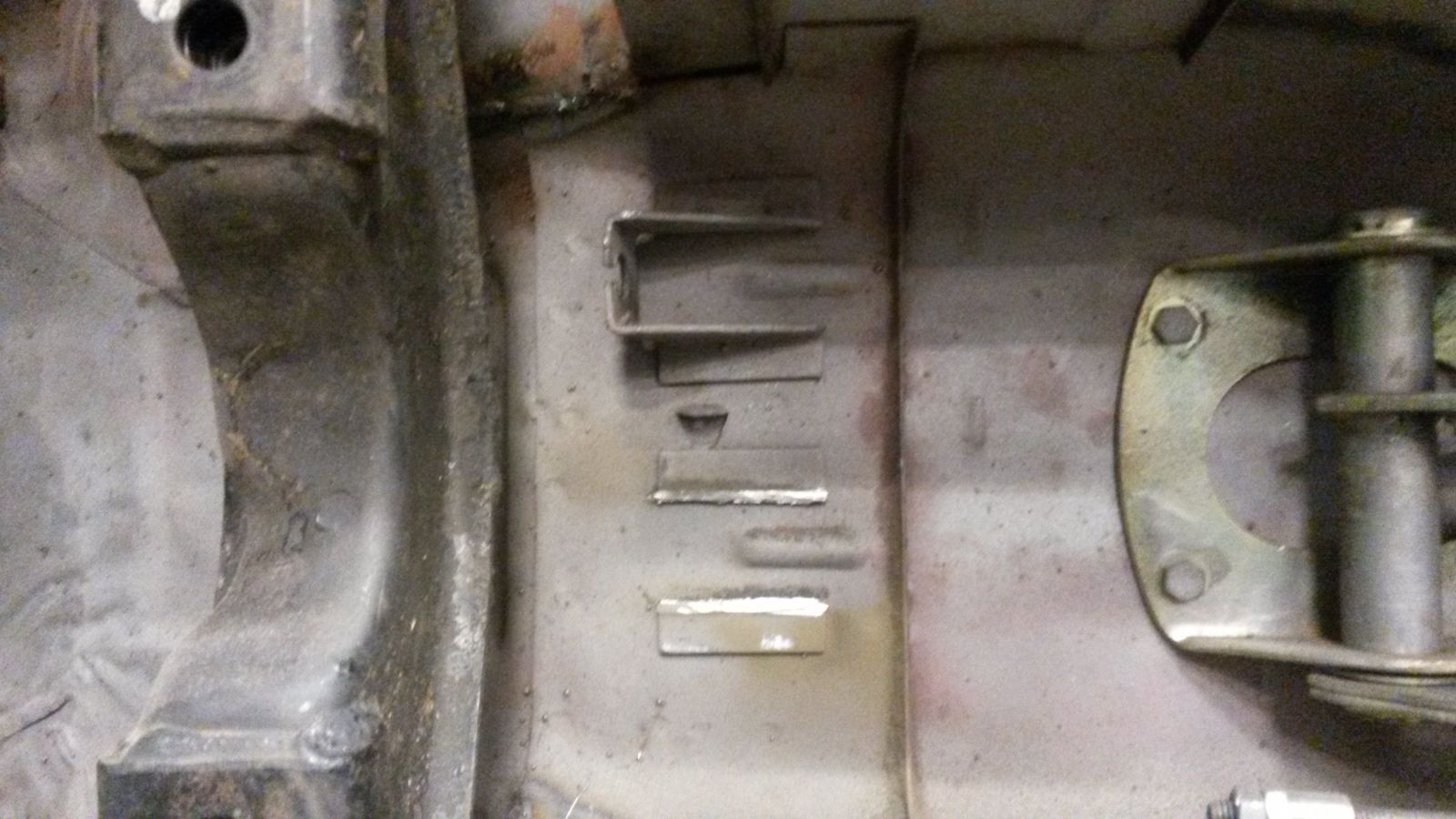
I cut out an opening where the cable will slip into the seat. The welds will prevent the seat from opening and allowing the cable to slip through.
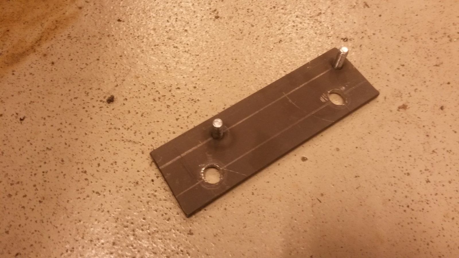
This is the fixing plate for the GTR-32 cables.
The original cable fixings had to come off.
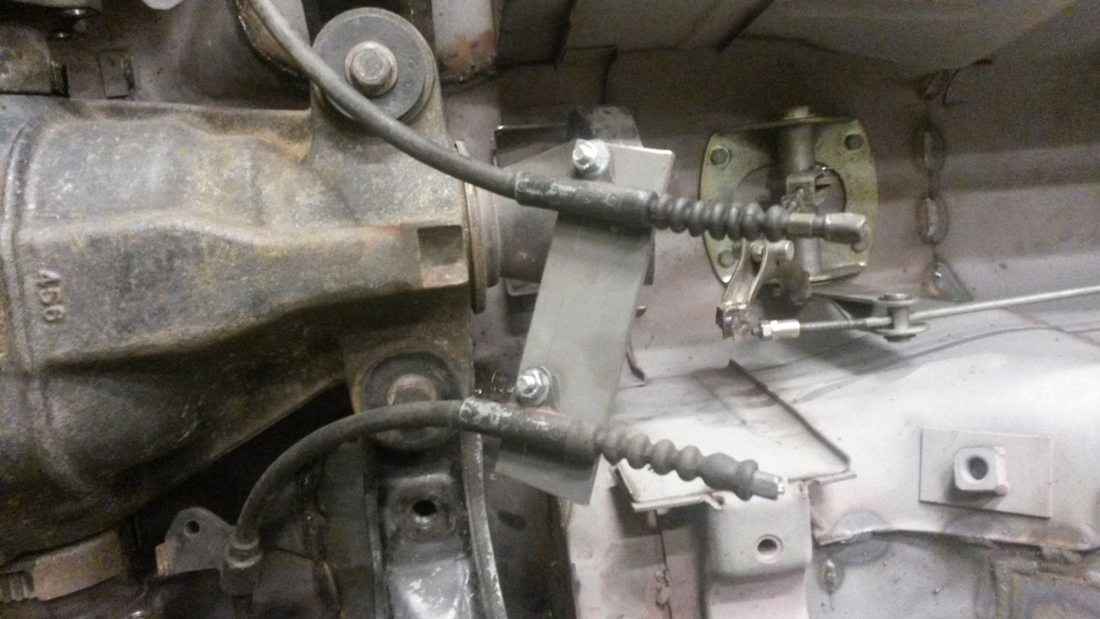
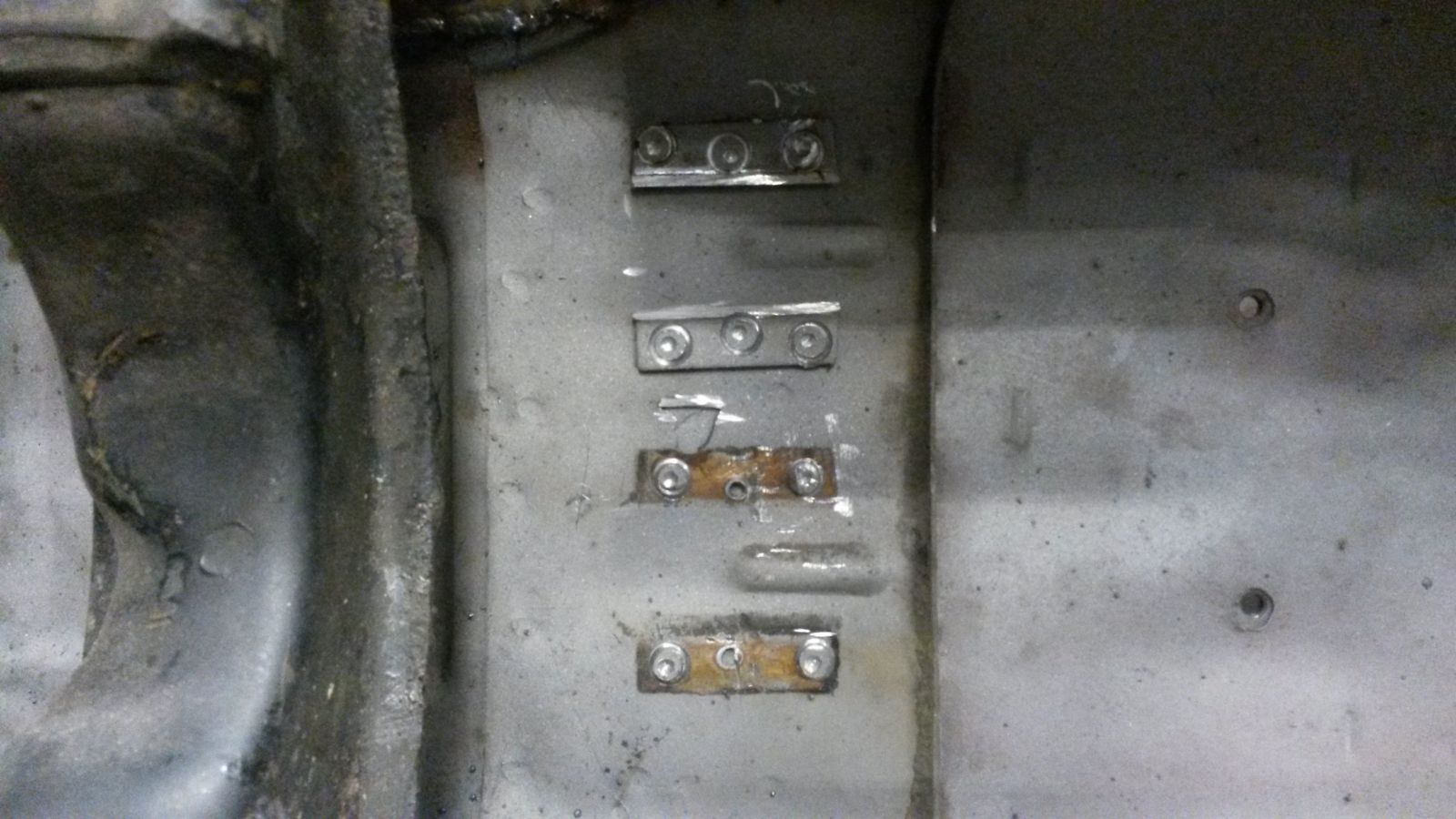
New cable fixing plate welded in place and cables slipped into the seats.
The puller is now closer to the lever axle. I replaced the original long bolt with a short hexagonal socket-head bolt and drilled a hole into the puller to allow for adjustment as depicted.
-
The cross member can take a much harder hit than any oil pan. Why even consider exposing the oil pan as the low point? You'll be thinking about only one thing whenever you see a bump.
This is a valid point. I will definitely be making a shield for the oil pan so that if I hit a rock or something, the shield will take the hit and the car will rise on top of the obstacle. Kind of like driving a boat on rocks.
I am only interested now on the subject of ground clearance and appearance, so please give input regardless of which powertrain your running.
-
I've been going back and forth and scratching my head upon the subject of ground clearance of my car with the V8 swap, since my oil pan will be sitting quite low.
I would appreciate some input from you guys in the form of numbers and pictures.
Please specify here your ground clearance and wheel specs with an accompanying picture of your car. Also state the measurement point that you used. The most preferable measurement would be from the longitudinal frame rail bottom surface to the ground.
Thanks in advance!


240Z EgoBoost by Boben
in S30 Series - 240z, 260z, 280z
Posted
I cut the custom steering axle extension rod to the correct length along with shortening the original steering axle and preparing a new fitting for the joint on the lathe. After test fitment, welded the stuff back together. I am quite happy with the outcome since the angles of the joints did not increase too much. The steering seems to be turning smoothly. I still need to modify the primary from cylinder number 5 to clear the rubber booth on the steering axle and also make a bracket for the support bearing, but I guess I am on the winning side regarding the steering.