Midnitz
-
Posts
42 -
Joined
-
Last visited
Content Type
Profiles
Forums
Blogs
Events
Gallery
Downloads
Store
Everything posted by Midnitz
-
VG Turbo manifolds can be ported to increase flow capacity. Extrude Hone also does a good job opening the internal volume up and leaving a polished smooth finish. I have seen people with stock VG30DETTs pushing over 500hp to the rear wheels on stock turbos.
-
One of the very best companies out there in engine management is HALTECH. Look them up and you will be suprised as to how affordable a stand alone system can be. I would also opt for a MAF driven system as well as a coil-per-cylinder set up. But this will require that you install a crank trigger mechanism. You may also need larger injectors to feed the larger demand for fuel. This will allow for you to develop some decent numbers provided the intake and cylinder head can flow to support the air the short block can move. Engine design is about making sure that the parts compliment one another to achieve a horsepower and torque goal. Cheers, Roberto
-
in good condition have cash in hand shipping to zip code 95348 or will pick up near the SF bay area.
-
Comparing a new Nissan 4 valve per cylinder engine to an older L series engine isn't fair.... Low end torque requires displacement and the ability to fill those cylinders at lower valve heights.(high VE%) The Nissan Titans 5.4 has heads that flow well at a reasonably wide powerband, the 4 valve per cyl heads have this characteristic. The valves are smaller but there are more of them...and the ports behind the valves are also more in number....this is good for high port velocities at low engine speeds and because there are two intake ports per cylinder....the engine can also breathe well at higher rpms. My comment is oversimplified but I hope it makes sense. If we could get our hands on 4 vale per cyl heads on our L series engines.....forget it...we'd be making some serious power.
-
I know longer runner length is good for low end torque but I am wondering if anyone has reportable improvements over an N42 intake.
-
check out boport cyl head work.
-
The car will be turbo charged. I like the idea of leaving the main diamters stock, the current size gives the crank strength and shrinking the size compromises that strength. Money is not an issue....All I have to do is talk to crower with a stroke size. I'll have to mock something up....pics to follow.
-
Keeping in mind that Nissan managed a 222hp out of a 3.0liter V6 in the 90s using 4 valve per cylinder technology and variable valve timing in earlier models, I'd say that 217hp out of a two valve per cylinder technology engine with less than optimal CFD research in the head /port castings is an accomplishment in itself. Not to knock Paul Rs portwork...but designs have their limitations. This is why forced induction is so attractive. With this said, focus on good cylinder head portwork, good balancing on the rotating assy, match the camshaft to the head flowrates. It is also a good idea to get the intake ported to match the heads' flowrates as well....this way you have a strong, tuned powerplant with no weak links.
-
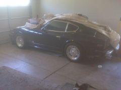 My Z is garage kept but I will be taking it in for a new paint job. I will stick with the Sikkens paint system. Estimated date of completion is summer of 2011. Before paint begins I plan on working on chassis and steering, installing: a new set of frame rails, sub frame connectors, 4 point roll cage, camber plates, shock tower braces Larger sway bars, New rack and pinion with bump steer brackets, new AC system (Nissan), Leather seats with lumbar supports etc. Mechanically: Build a larger than 3.2L stroker given block clearance WITHOUT taking the bore to its max size. Turbocharge it, tie it all together with a Haltech ECU and a coil pack per cylinder setup along with a rebuilt T5 and a centerforce clutch. I will save lots of money fabricating or modifying much of the things myself. Pics will be added as the project progresses. For now, this is our kittens' bed at night.
 -
75ish 280z
-
-
From the album: MIDNITZ
-
--------------------------- Thanks for the good comments.....I may be interested in doing something different. Seems we're all stuck with a 3.1 or 3.2L stroker and that seems to be about as far as we can take it using stock parts.... I am curious to see if I could fit a custom ground forging with an even larger stroke (plus 5-8mm more).....anybody know of clearance issues? I think I may have to mock one up and spec my own design of crank....using the VO7 as a measurement sample. At $2600 for each crankshaft...I want to get it right. Bore skirt and block sidewall clearance grinding are ok so long as they are minimized. *curious*
-
I have the N42 block and was wondering about maxiumum stroke we could use on the existing castings.... I may provide dims from the LD28 crank I found and have Crower cut me one out of 4340 alloy....Since I can control the stroke dimension and the rod length as well as piston compression heights....what do you guys think I can get away with in terms of maximum displacement?
-
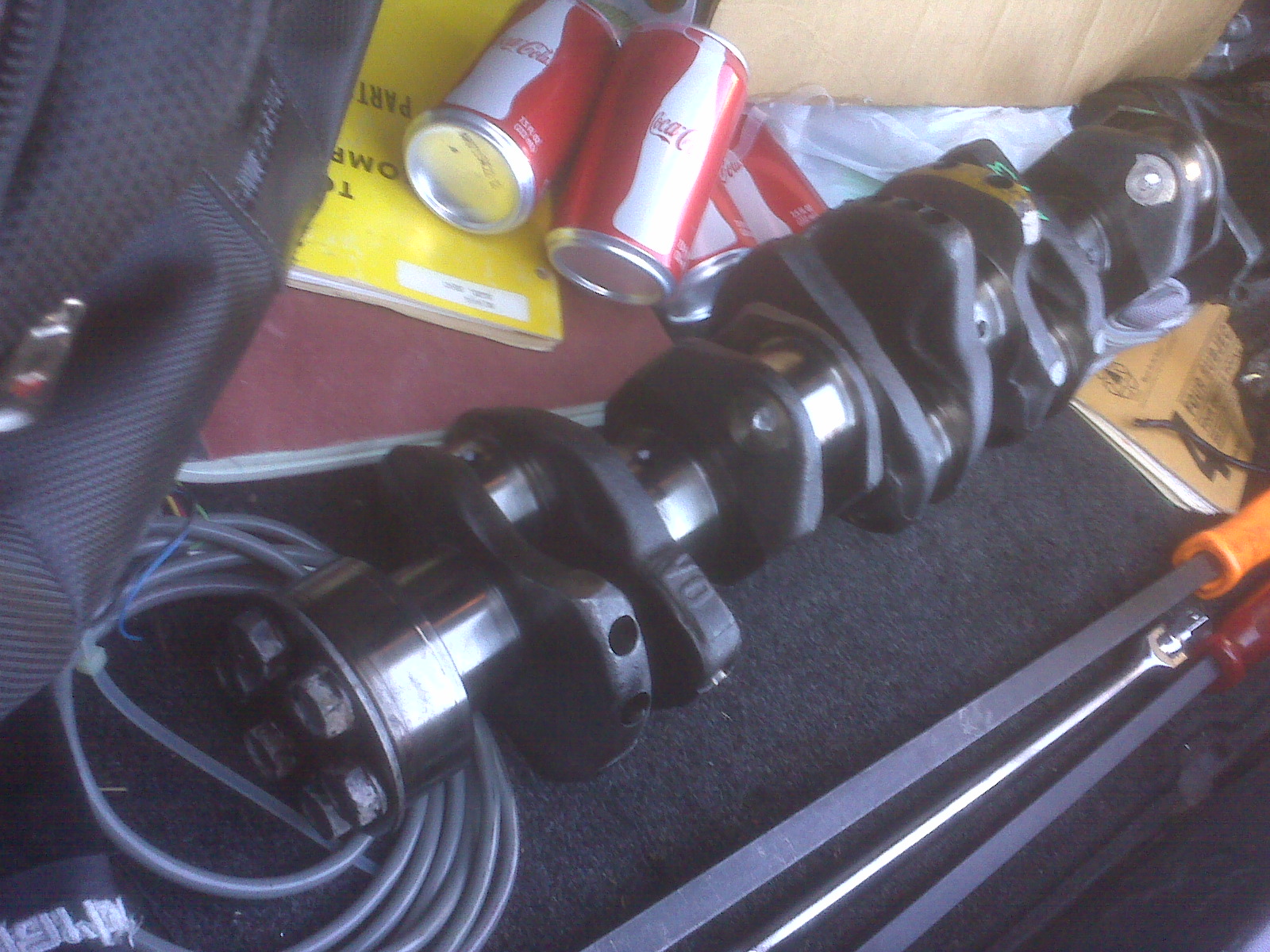
Gentlemen, I have decided to commence a project to build a 3.1 stroker for my 280z. After emailing numerous people and finding all have been sold, I searched the picknpull site and found maximas of the right year and when I went to check one in San Jose....I found one equipped with a diesel engine!!! A coworker and I spent the morning pulling the engine and removing tons of parts to get the oil pan off.... All of the bearings looked good....the dry film lube on the bearings was still present and no copper visible. The only copper visible was the center main bearing thrust surfaces....but the wear indicators were far from bottomed out....so the crank is in excellent shape!!! Now off to the crank specialists for lightening, knife edging counterweights, cryo process as well a balancing with the rotating assy. Planned for rotating assy are: New Pauter Rods Ross dished pistons for turbo charging Total seal piston rings stock 280z harmonic balancer lightened flywheel from MSA Stage three ported N42 head with welded and reworked exhaust ports, ferrea valves and a custom grind camshaft. Stage 3 ported N42 intake Modified Spearco intercooler (all intake and intercooler and impeller side of the turbo are TLTD coated for thermal dispersion) ECU = Haltech Injectors TBD Turbocharger: Single T3/T4 ceramic bearing turbocharger with custom built and coated header I will post pics from time to time showing progress.

-
The final size of the TB assy depends on what the vehicle will be used for. TB size and intake manifold runner shapes play a large role in mitigating turbo lag. After turbos spool up, VE increases like crazy. If you're pushing 400BHP, I would Keep the stock TB assy and focus more on intake port/flow work. Until your engine experiences the boost, it is just another engine drawing air by vacuum. Balancing lag mitigation and top end power will ultimately lead you to a decision.
-
regarding TB sizing, bigger doesn't always mean more airflow. Intake air velocity will have more of an impact with volume of air than shear size opening will. The larger the TB assy on an L28 (even turbos) the less off idle response you will get. This moves the torque curve up the rpm ladder. I purchassed a big throat to augment extensive head and intake work. Camming the butterfly shaft will be in the works. I have to finish the ET upgrade first.
-
"Bullshit. Cryogenic treatment is a stress relieving process (primarily for steel) which further transforms a percentage of retained austenite into martensite. This increases the abrasion and chipping resistance of the steel and increases its toughness (ductility). But the 400% claim is complete crap" ----------------------------- I laughed when I read this. It is used as a stress relieving process and is primarily used to improve the toughness. This improves wear characteristics. If the material being stress relieved already has stress risers or "slip" in its lattive structure, then the cracks will propagate regardless of the martensite content.
-
Get that N47 head and have Rebello perform portwork on it. These old nissan castings also have port taper issues....an intake port needs to decrease in volume leading up to the roof and floor radii. Intake ports on N42s grow up until the valve guide and open up into the pocket...this is not good for making power or good low valve lift flow. The volume growth makes the air charge slowdown. The exhaust ports also need welding and reshaping to flow decent numbers.When flow benching, be sure to check flow at .5in valve lift incriments.
-
Nissan 5 speeds. I was running a well built L28, 9.5:1 comp, stage 2 cam, ported intake and head, 6 to 1 header, aftermarket ignition and a cold air filter setup. The transmission was stuck in 3rd gear and the 5th gear retention screw had begun to back off. $1500 later, the trans works...but makes humming noises intermittently. Currently looking for a T5 as I have upgraded to L28ET.
-
Ok, I have finished the detailed drawing for the flange....and because I have an N42 head I will start with a rectangular shaped port flange. 0.375in thick. I will have it water jet cut for tighter tolerances (less interference issues). I love Mastercam... I'll take pics of the cutting process and upload as soon as practical. I will also make a copy of the solidworks file and make a round port design for you round port lovers. I've been seeing some good examples of what to do and what NOT TO DO. Keep the feedback coming, hang in there...next week is going to be quite a bugger for me...so no progress next week. Material choice will be a low-carbon steel alloy and once weldment is completed, a prep and coating of titanium-ceramic thermal barrier coating to round things out. So far, it looks like cost for this thing will be pricey when compared to regular off the shelf headers for a V8.
-
Thanks JSM! My dims will be a bit different....the turbo flange will be centered a bit more towards the front....to create clerance for the steering shaft. I may create a foam mockup of the header/turbo setup....and see how it all fits under the manifold. I'll be posting pics as I go....
-
I have the primaries turning downward now and heading for convergence towards the flange boundries...I will post more pics later... got a massive project to work on right now... Busy busy!!
-
---------------------------------------------- You can have all of your mentioned factors in an engine....but if the cylinder head, intake and exhaust systems are "restrictive" for the desired powerband, then i'd say one would have a non-optimized or de-tuned engine. Street bikes (as well as high dollar multiple valve per cylinder engines) do indeed use smaller ports and valves...but the number of valves/ports filling/scavenging that cylinder are increased (this leaves a larger valve surface area than one large valve)....designers have used this to keep port flow velocity higher at a wider range of valve lift and over all rpms. Re: big ports = moving powerband up the rpm ladder , I was making reference to the L28 head where one has a single intake and exhaust. Typically, the larger one makes the intake or cyl head port, the slower the port velocity at the given rpm and valve lift....this usually kills low end torque, with the expected payoff being in the upper midrange to top end. Notice I haven't even mentioned cams...it's usually the lower # LSA, higher duration and lift units that will move the powerband to a higher rpm range. This is why I advocate looking at the engine design as a complete assembly, using parts with characteristics that are compatible. Breaking things down into moments wherever possible. The pitot probe is a good addition, but don't discount the flowbench as a verification tool. Just be sure that the person performing the testing, knows the proper test setup. Cheers, RL
-
------------------------- Flow rate is a good guideline to help establish flow characteristics based on what the engine will be used for. You are indeed right that raw, large numbers can be deceiving. One must perform portwork keeping physics in mind. Larger volumes will indeed slow the port velocity down at lower flow rates....effectively moving the VE% window up the RPM ladder. This is one reason I don't open the port size up too much. Most of my work pertains to work in the upper radius and valve pocket as well as the valve seat and guide areas. I also like to use clay to help model the port before I add material. My work mostly ends up being the equivalent to a Stage 2 cylinder head. Flow benching helps verify that the ports are balanced. Flowbenching also helps as a verification tool. The pressure differential Pitot probes are good when you want to break the port down into "moments" of flow WRT port position....and yes it does take the portwork up a notch qualitatively. But one must setup a flow bench properly to make sure the port is going to receive the amount of flow it would see given RPM increments. Your readings are only as good as your setup. This is also why I asked if the flow work was broken down in increments. Good Discussion!
-
------------------------ You should have the head flow-benched by an outside vendor....the ports should have a progressive drop-off in flow (A place where the flow delta runs flat), Of course, things change when the force behind the valve is pressurized.... Things to consider in the long run: 1. define what the head does 2. finalize the boost level you will settle on 3. tune the cam to the intake-head flow. In the end, it will be quite the beast. Then you can work on keeping the rear tires stuck to the pavement....but this is a good problem to have.