onephatz
-
Posts
99 -
Joined
-
Last visited
-
Days Won
1
onephatz's Achievements
")
Newbie (1/14)
1
Reputation
-
see, now you know why I hang out in a den of other car dorks. thanks
-
I'm trying to figure out what car this is. anyone know?

-
the link for the PDF of the part with dimensions is. http://finitecell.com/280z/bracket/280z-300zx-rearbracket-cut.pdf the link for the AutoCAD file for the waterjet is http://finitecell.com/280z/bracket/280z-300zx-rearbracket.dwg Also, as a bonus, I was looking around my garage for bolts to work with this thing to make sure it all fit right and found the bolts from my front brake upgrade. It seems that the bolts you remove from the front rotors to install the toyota 4x4 caliper upgrade for vented rotors are the exact right size for a 1/2" thick piece of metal. Not saying it's perfect or even lightweight, but it is mighty convenient.
-
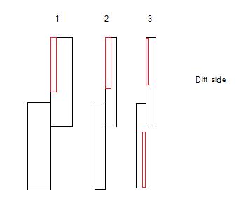
There seems like there are three "simple" ways of making the attachement. number 1 is the current method using 1/2" material number 2 is the same method but using 1/4" material and number 3 is cutting off 1/16" material from both faces the get the same offset. I chose number 1 for a couple of reasons. first, the pad bracket is held to the hub by two ears. if you start with 1/4" material and cut off 1/8" you are left with 1/8" material left to hold all the braking forces. if using 1018 steel this should be able to take all the load with a factor of safety of at least 4. for some reason I get a little squeamish thinking about what might happen if the tabs bend instead of fail in sheer. I suppose we could start somewhere in the middle at say 3/8" material and go from there but we'll have to see. second, I wanted to minimize the machining time required to make the brackets. if I can make them with one or two passes on one piece, that saves money both in terms of time and equipment. if there is a better way to get the offset of 1/8" I'm open to discussion. also, I can provide a solid model for anyone who has access to FEA software that wants can find out how this responds to load at different thicknesses. Jesse
-
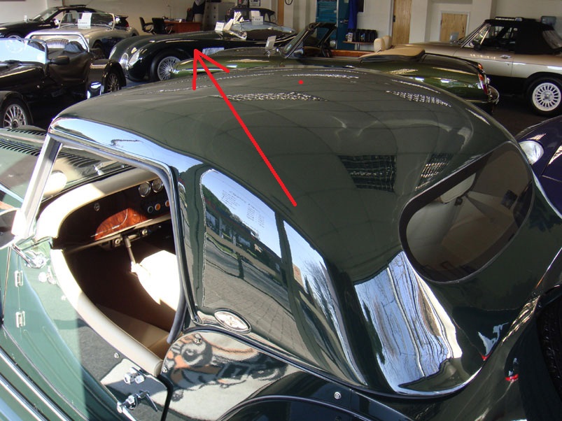
All good responses. This has been a first iteration and I'm sure there will be several versions as I go along. I was actually thinking about how to align the two pieces by having a v cut in the top to line the two pieces up. I'm not sure why most calipers are oriented as they are but it might have something to do with the internal structure of the caliper that facilitates bleeding the system. I haven't got the system completely plumbed up yet but as soon as I get the hose hooked up that clears the axles, wheels, and swap bar I'll post that up as well. John Yes. you are correct that 1/2" steel is a bit of an overkill but, to make the geometry easy to manufacture and assemble, 1/2" steel was the easy way out. you use a single sheet of steel and only have to machine strait cuts off the back piece to get the geometry that works. unless you know of a better way to get the setback from rear face of the bottom piece, the simplest solution that I know of is to take a overly large piece and cut it down. let me know what you think jesse
-
Background: So I wanted to get better rear brakes on my car but didn't want to spend most of my paycheck on an off the shelf solutions already in play. The Modern Motorsport bracket looked really nice but resulted in less than bleeding edge braking performance. The 240sx caliper just wasn't big enough to lock the rear tires when sized to the Toyota 4x4 front upgrade. Brake pad compound could have been changed or other adjustments made but I wanted a rear caliper/rotor that would be overly large and need to be backed off with a proportioning valve of some sort. Result: Parts 84-86 300zx rear n/a calipers and pad brackets 84-85 300zx rear n/a rotors 84-86 300zx rear n/a pad one set of custom brackets new brake lines Now I'll go thru the process and show the results. I'll also post up the autocad DWG file needed to have it cut out. Step one, have the bracket cut out at your local waterjet using 1/2" steel. Chuck the top piece into a Mill and cut off 1/8" off the ears to set the pad bracket back far enough to clear the rotor. the bottom one is for the passenger side. as with most things in life it doesn't have to be perfect it just has to be close. I designed the top and bottom pieces so that the top of the bottom piece should line up exactly with the top of the top piece. clamp it together and weld it together. try and align the ears center to the lower piece but as before "close" is good enough. make sure to weld both the top and the bottom. How it looks attached to the car without the rotor. clearance between rotor and bracket. Clearance between rotor and pad bracket. as you may note, the bracket could have come back another couple of thousandths to center the rotor in the slot. Two thoughts. First, if this is a diy project cutting off 1/8" (0.125") is way easier than cutting off 9/64". second, as stated before, doesn't have to be perfect, just has to be close. Pad placement. With caliper. Now this is just a start, I'll update this thread as I get more data and more info on brake hoses and CAD files ect.
-
dailydrifter I'm looking at getting the same wheels you purchased but really need to run a wider tire. could you take a picture from under the car of the clearance between the tire and the strut tower in the rear. if you have coilovers, could you raise the car a bit to run wider tires and prevent the rubbing of the fender? thanks jesse
-
What is Compressor Surge? - Explanation Within
onephatz replied to ktm's topic in Turbo/Supercharger
Tony I was kinda thinking that route but let me show you what I'm talking about. Below is the compressor map for the s-trim with a line drawn assuming that the supercharger is setup for max rpm and an engine rpm of 6000rpm. my initial idea was to have a wastegate actuator connected to a throttle body of sorts after the compressor and before the intercooler to open when the desired boost level is reached and just vent the rest (hence the knee). I have now come to the realization that it will become unstable before reaching the desired boost level. vortech s-trim on vg30e, drawn line for 3000-6000 engine speed/air consumption now if I'm hearing your right, there is really no way of producing stable flow without increasing the flow thru the supercharger. well,.......what if there was a one way valve after the compressor that started to vent at say 5psi and would be large enough in size to allow just enough "extra" flow to prevent the unstable condition? that would effectively change the angle of the line to put it just inside the stable region of the compressor. does this sound correct? what happens if I do the wastegate thing at the higher supercharger rpm? how might the surge line change with a higher impleller speed at a governed boost level? -
What is Compressor Surge? - Explanation Within
onephatz replied to ktm's topic in Turbo/Supercharger
Tony I've got a question, I recently aquired a vortech supercharger dirt cheap (s-trim) and wanted to try some fiddling with it. my goal was to attach it to a vg30e and run ~10 lbs of boost thru the thing. the problem is, it's waaaaaay too big for the motor. before someone goes spouting off about how I just need to put on a bigger pully to slow the speed let me explain. I want to pully the supercharger up so it's operating at it's max rpm when the engine is operating at it's max rpm. now this poses a big problem since even under normal operating conditions the engine can't consume the required amount of air to prevent a surging problem given the setup I want. now since the supercharger speed is tied directly to the engine rpm and not the exhaust volume, how would you prevent surge from occuring during a normal run up in rpm. the goal is to have 10lbs of boost from 3-4000 rpm to red line like a turbo but without the surge. I've got an idea of how to do this but want to get your input first. jesse -
the fuel, e85, does not corrode anything any more than gasoline does. the problem with e85 is that it absorbs alot more water than gasoline does. fuel lines made of carbon steel will can be corroded much faster than regular gasonline because of the water content. that's why most e-85 cars/trucks run stainless steel fuel lines. that is the ONLY corrosion related reason. as far as the rubber is concerned, yes e-85 will swell natural rubber but most if not all rubber put into cars today is ethanol compatable. would a car that is capable of running 10% ethanol be compatible with fuel that is 85% ethanol? yes stricktly speaking, but the comptuer does not have the ability to adjust the fuel enough to compensate for the change in required afr.
-
so as some of you may know I have an 82 maxima with a ford 302 in it. it's really been a while since I've done anything with it but I was going thru some old files and came across a excel file projecting my horsepower and torque. these number were based solely on stock dyno runs of mustangs and such, ie: peak torque numbers projected for stock cars. I subsequently went to the dyno to find out what I was putting down for a stock 5.0. well I didn't put the two together till today and was I suprised. as you know, the fuel bins in the megasquirt table should correspond to your torque curve and using that can project horsepower. here is my real vs projected horsepower and torque based upon my fuel map and a guessed peak torque. as you can see it's a pretty damn good correlation but I think my fuel bins are alittle rich below 3000rpm. jesse
-
Ford Eaton Lightning Supercharger GEN III truck LM7 5.3 6.0
onephatz replied to zgeezer's topic in Turbo / Supercharger
If I remeber correctly ford used the eaton M112 supercharger on those years. I don't know of anyone who make a intake manifold that would allow you to "bolt on" that supercharger. the housings were made specificly for the ford lower intake however, you could proubly have one fabbed up to mount that thing to. the other option is to mount the supercharger on the side of the engine some place and run piping to it. jesse -
This video reminds me of a road between willits, ca and fort bragg, ca. There really isn't a strait stretch in it. There are some sections that it's literally right, left, right, left, right, left. Oh how fun.
-
the only way to get your low end spool and your high end power is to do as toyota and mazda did on their late model sports cars. have all the exhaust run to one turbo till it maxes out then a exhaust gate opens and allows exhaust to the other turbo of equal size. the two turbos combined should allow for the upper limit of what you want in top end.
-
you are a wonderful man. you know this right.... thanks john