

inline6
-
Posts
453 -
Joined
-
Last visited
-
Days Won
3
Content Type
Profiles
Forums
Blogs
Events
Gallery
Downloads
Store
Posts posted by inline6
-
-
Any updates, Speedtripper?
-
Anyone have any dry sump parts for the L6? I am looking to switch from a wet sump oiling system to dry sump.
Garrett
-
My Maxima block will be machined this week and we'll see what is possible with it. The plan is to go to wet liners. It would be amazing if the block will take an 89 mm bore. I don't think it will. If we break through, we'll keep going to 88 or so mm and examine the height of the deck and the height of the floor of the block. Should know more soon. I wish I could get my hands on a block that would take a bore of 89 mm. I tried looking for a Nissan Patrol diesel block on a couple of auction sites in South Africa. Nothing on either of those.
-
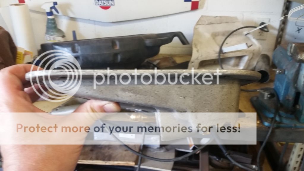
I finally got around to dragging it down. It may have less clearance than a stock pan! The "sump" is a 4"wide tray that runs the length of the pan on the drivers side. It measures about 3" from block to lowest point.

Uggh. Need to be able to drop the engine down at least 3/4". Thanks for taking the time to measure and provide the pic.
-
I've never come across this one before - automated engine block machining? Automated transmission assembly? Early computer aided design (CAD)? Definitely some interesting footage:
-
 2
2
-
-
I got the diesel LD28 block I was looking for. Thanks to those who offered.
-
Not sure if this topic is no longer the flavor of the decade, but I am in the process of a very similar build with a LD28 block. Block has been bored to 89mm. Min wall thickness of 3mm. Interesting to see the wall thicknesses are in the 3mm - 5mm range. So there is some shift in the core.
If anyone is interested in this build, let me know, and I will post as things happen.
So, you've sonic tested after boring and have 3 to 5 mm?
Yes, very interested in seeing more about this engine. I am exploring using an LD28 block for a new engine. My engine builder started examining the one I just sent him. It came from a US spec Maxima. He knocked out the front and rear freeze plugs and estimated the bore thickness at around .220". However, he notes that there are spaces between the as cast bores, meaning none of the bores are siamesed. He's going to sonic test a few of them to see what we're faced with. IF the bores are around .220" thick, we MIGHT be able to bore to 89 mm and have .120" (3 mm wall left). He is very doubtful...
Maybe those Patrol engines are different?
-
Awesome. Glad to help.
-
Yes, that would be helpful. I was planning on buying one soon so I could take measurements. I'm not sure how to go about lowering the engine as much as possible, thus the reason for the post. Dropping the engine means dropping the front of the transmission. I assume dropping the front of the transmission means dropping the back also (will need a custom transmission mount). My initial thought is to lower the engine 3/4" to compensate for the extra height of the LD28 block. That would put the header (and custom exhaust) back in the same location as it was with the L-28, and solve the hood clearance problem. But, while I'm here... I figure I need to explore the possibilities.
-
Anyone running a dry sump set up with an ARE pan? I'm looking into it and thinking about lowering the engine. I'm interested in lowering it by using custom or modified engine mounts. Curious if anyone has done this or something similar.
Garrett
-
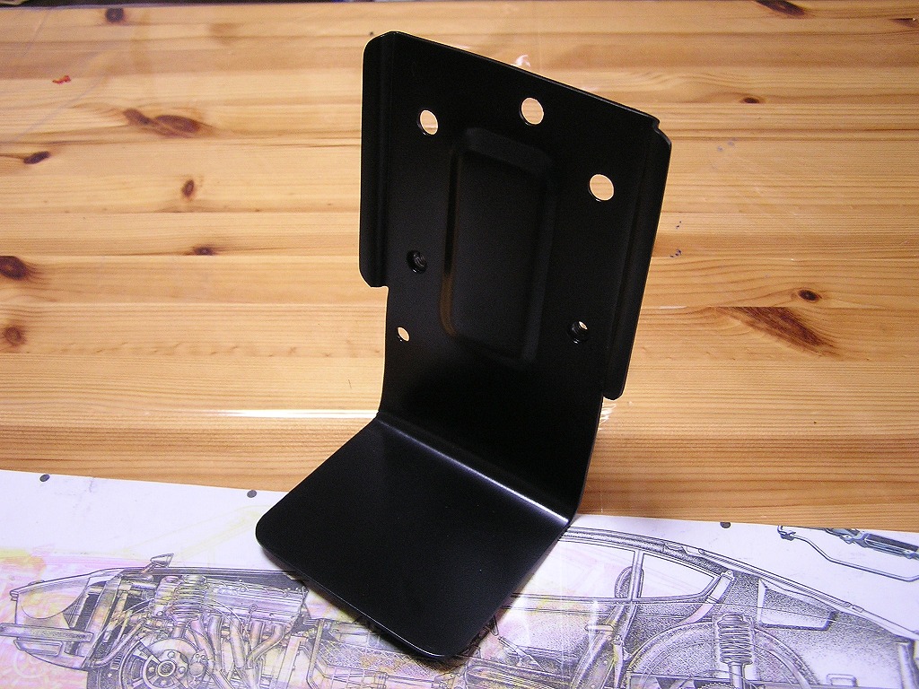
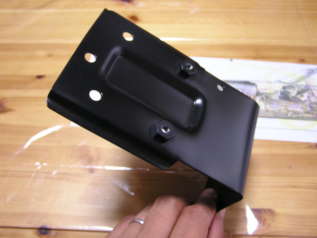
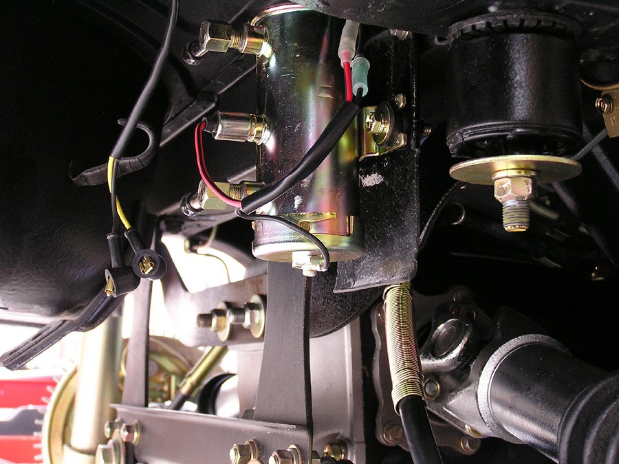
I saved these pics from somewhere online years ago. This guy was doing a very accurate/faithful restoration and had this bracket custom made to be like the original. I made a simple L shaped bracket and bolted it to this same location you see in the third picture (pic is not my car). There are two nuts already welded to inside the car frame that are there specifically for the fuel pump bracket.
I made my bracket out of .100 thick mild steel. You'll want to make it longer than the height of the fuel pump so it can serve as a shield to keep road debris from bouncing up and hitting the pump, hooking on the pump, etc. You can find rubber grommets at auto stores that are the right size - I think I got mine from Advance Auto.
Regarding wiring:
I recall being able to find several people who wrote about it online, perhaps on this site. I remember reading about members who wired in auto "cut-off" switches of different types... so the pump turns off in an accident situation. You would be wise to so.
On my 12/70 series one car, there is a factory connector "taped" to the wiring harness in the center of the dash with blue tape. If I recall correctly, you can get power to the pump (key position "on") by putting a fuse like this in place on that harness connector (thereby joining the two connections in the harness plug). On my car, that wiring goes to the electric fuel pump location in the rear of the car - I believe it shares the wiring for the tank sender unit. My pump was just like the one in the picture above, it only had one wire, and it was for the 12V power. My pump body had to be connected to ground for it to operate - again, like in the picture above.
-
Hi Rick,
Thanks for the note. I have paid for one that will be shipped to me in a couple of days. I'll let you know if the deal falls through.
Garrett
-
The google site specific search works in Google images also. So, if you are looking for pictures of something specific on hybridz... voila!
-
I typed this up for my engine builder via email, so I'll share it here also:
There is a section of the Honsowetz book about bending heads:If a significant amount of welding is to be done or if only a little amount of material can be milled to straighten the head after welding, it is best to bend the head backward-up at the ends. After bending, the head gasket surface will be convex. This pre-bend will compensate for warpage that bends the head in the opposite direction (concave) that occurs when the combustion chambers are welded. The amount of preload or bend depends on the location and amount of heating or welding.Bolt the head upside down to the deck of the stripped block. Support the head off the block with a spacer block at its center. The spacer should span the width of the block, be approximately 1-in. wide, and at least 0.100-in. thick. Secure each end of the head to the block with two short head blots. Gradually tighten the bolts and check the bow in the head with a precision straightedge and feeler gauges.You'll need a 36-in. long straightedge for checking a six-cylinder head; 24-in. will do for a four cylinder head. With the straightedge flat against one end of the head, check the gap at the other end using your feeler gauges. How much prebend you should put in a head is subjective. It depends on how much welding will be done. This is something you and your welder must judge. Use the following as a guide: For small to significant amounts of welding, pre-bend 0.020-0.040 in. for a four cylinder head and 0.020-0.060 in. for a six cylinder head, respectively; 0.020 in. if there's a minimal amount of welding to be done and 0.040-0.060 in. if you're going to do a lot of welding. If you guessed right, your weld-repaired head will only show 0.005 - 0.008-in. warpage after it has cooled. Use your straightedge and feeler gauges to check. Whatever is required to clean up the head, the same amount must be milled from both sides.Welding Combustion Chambers to Increase Compression:As mentioned previously, the head must be absolutely clean before you can weld the combustion chambers. This applies to both old and new heads. Polish the chambers with cartridge rolls, then with a rotary brush. Bend the head backward the maximum amount because welding all combustion chambers is a significant amount of welding. Therefore, using my recommendations, a four cylinder head should be bent backward about 0.040 in and a six cylinder head about 0.060 in. Instruct the welder to "jump around," or weld a small amount in one area at a time. This will keep welding heat from being concentrated in one place, thus helping to reduce warpage and prevent cracking.Honsowetz also has a section on straightening heads. Basically, it consists of bolting the head upside down on an engine block and using a spacer and bolts as above. He says to tighten the bolts until the head is bent backward about 1.5 times the amount that it is warped. He again uses a straightedge and feeler gauges to set it up. Then he describes using a acetylene torch with a rosebud tip to evenly heat the entire head to 350F. He describes using temperature indicating crayon or paint and marking the head in many locations. It can take up to 30 minutes to heat the head to 350F this way. -
Isn't there some information in the Honsowetz book regarding amounts of pre-bending before welding the head?
Yes, the Honsowetz book gives the exact methods of pre-bending the head when re-shaping the chambers for a better quench area. Off hand, I believe you torque the head on upside down with a piece of 1/4" bar stock in between the middle of the block and cylinder head. I would have to re-read the book to know for sure.
Awesome. Evidently, I haven't memorized everything from that book as I thought I had. Thanks for the info.
-
Reason I am asking is we are thinking of pre-bending... before welding, so less straightening, or no straightening, if we get really lucky, will be necessary.
-
Wondering if anyone has any experience with what I can expect (approximate head warpage) when welding either an N42 or P90.
-
bump - no one has robbed a crank from one of these engines and has a leftover block?
-
My tires checked out ok. I went to a local shop and spoke with the owner who races a few different cars on a weekly basis. While the wheels were being checked I decided to remove the entire front suspension components off my Z and have a good look at them. What I found was 1 bad ball joint and a bad inner tie rod....nothing lasts for ever....
So now I have to find a shop that will let me use some machining equipment so I can make some new steering rack parts........then find/purchase some heim joints...
Then the Z will have a completely new front suspension and steering setup.....again...
Were both of those aftermarket?
-
Strange that they went bad with only about 7000 miles, but they were not OEM. So there is that.
As a 16 year old, I used to get miffed when a shop wouldn't allow me to buy parts and have them install them. With lots more years behind me and the wisdom of traversing through them, I realize that only when it is possible to determine they are "white boxed" original suppliers to OEM, or high quality from proven track record, do I use them. Wrong metallurgy and or specs and aftermarket ball joints can wear out in 7000 miles for sure.
-
I was instructed by David Weber of Malvern Racing never to run the plastic spacers with o-rings. According to Dave, the carbs have to be "isolated" from vibrations to work properly. He told me to run rubber isolators. These use gaskets instead of o-rings. No leakage issues are another benefit.
Here is a pic showing them between the carbs and the manifold:
-
I chased shimmy problems in my Z on and off for several years (shimmy was always there, but efforts to find it were "on and off" ). I replaced tires, wheels and tires, rebalanced several times, new compression rod bushings, new inner control arm bushings... I even rebuilt a good steering rack with all new factory parts including new inner and outer tie rod ends. Still had the problem. I even messed up said rebuilt rack because the rack gear and pinion wore at dead center because of the continued shimmy, before I found the problem. In the end, I replaced the only components that hadn't been replaced... the lower ball joints. I hadn't replaced them before then because they were the newest parts on the front end when I bought the car. And sure enough, they were the problem. They were aftermarket. Even though the boots were good and the outside of the joints looked fairly new, the joints had worn. I put new OEM joints on and haven't had a shimmy since. And by the way - for some reason that speed range ~45 is tell tale. If your shimmy goes away again at 50 or 55 and you are smooth above that - I would suspect the ball joints big time.
G
-
I'll let you conclude things with abdi first.
If that should fall through, I have what you are looking for. Diff is indeed a 4.38 with K on the top of the case.
-


3.4L L28 stroker
in Nissan L6 Forum
Posted
Thanks for the update. My engine builder recently completed making some mandrel adapter rings which, as I understand it, will be used to locate/hold the block while they bore it out.. We are going to bore both an L28 and an LD28. With the L28, we're going to go to something like 92 mm (I forget precisely the number). We are trying to remove all of the bore so we can examine the thickness of the deck and the bottom shelf of the bores. This is just to provide any information that may be helpful with regard to liner design.
With the LD28, we'll try to go to 89 mm, but given others experiences that we know of here in the states, we aren't giving that a high percentage of success. This is why I find your information so intriguing. Anyway, if upon examination of the L28 bored out we see there is still promise with using a wet liner, then if we break through the LD28, we'll keep going until the bore is gone on that one also. Then we'll have to see if we can come up with a final design of the wet liners.
Thanks again for the info. I wish I had your block.